

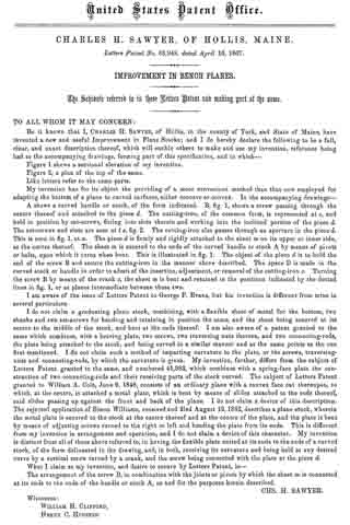
| PLEASE NOTE: The images presented on this page are of low resolution and, as a result, will not print out very well. If you wish to have higher resolution files then you may purchase them for only $2.95 per patent by using the "Buy Now" button below. All purchases are via PayPal. These files have all been cleaned up and digitally enhanced and are therefore suitable for printing, publication or framing. Each zip package contains all the images below (some packages may contain more), and purchased files can be downloaded immediately. |
UNITED STATES PATENT OFFICE.
_________________
CHARLES H. SAWYER, OF HOLLIS, MAINE.
Letters Patent No. 63,948, dated April 16, 1867
_________________
IMPROVEMENT IN BENCH PLANES.
_________________
The Schedule referred to in these Letters Patent and making part of the same.
_________________
TO ALL WHOM IT MAY CONCERN:
Be it known that I, CHARLES H. SAWYER, of Hellis, in the county of York, and State of Maine, have invented a new and useful Improvement in Plane Stocks; and I do hereby declare the following to be a full, clear, and exact description thereof, which will enable others to make and use my invention, reference being had to the accompanying drawings, forming part of this specification, and in which —
Figure 1 shows a sectional elevation of my invention.
Figure 2, a plan of the top of the same.
Like letters refer to the same parts.
My invention has for its object the providing of a more convenient method than that now employed for adapting the bottom of a plane to curved surfaces, either concave or convex. In the accompanying drawings —
A shows a curved handle or stock, of the form indicated. B, fig. 1, shows a screw passing through the centre thereof and attached to the piece d. The cutting-iron, of the common form, is represented at e, and held in position by set-screws, fitting into slots therein and working into the inclined portion of the piece d. The set-screws and slots are seen at t s, fig. 2. The cutting-iron also passs through an aperture in the piece d. This is seen in fig. 1, at n. The piece d is firrnly and rigidly attached to the sheet m on its upper or inner side, at the centre thereof. The sheet m is secured to the ends of the curved handle or stock A by means of pivots or bolts, upon which it turns when bent. This is illustrated in fig. 1. The object of the piece d is to hold the end of the screw B and secure the cutting-iron in the manner above described. The space D is made in the curved stock or handle in order to admit of the insertion, adjustment, or removal of the cutting-iron e. Turning the screw B by means of the crank c, the sheet m is bent and retained in the positions indicated by the dotted lines in fig. 1, or at places intermediate between these two.
I am aware of the issue of Letters Patent to George F. Evans, but his invention is different from mine in several particulars.
I do not claim a graduating plane stock, combining, with a flexible sheet of metal for the bottom, two shanks and two set-screws for bending and retaining in position the same, and the sheet being secured at its centre to the middle of the stock, and bent at the ends thereof. I am also aware of a patent granted to the same which combines, with a bearing plate, two screws, two traversing nuts thereon, and two connecting-rods, the plate being attached to the stock, and being curved in a similar manner and at the same points as the one lirst mentioned. I do not claim such a method of imparting curvature to the plate, or the screws, traversing-nuts and connecting-rods, by which the curvature is given. My invention, further, differs from the subject of Letters Patent granted to the same, and numbered 41,983, which combines with a spring-face plate the construction of two connecting-rods and their receiving parts of the stock curved. The subject of Letters Patent granted to William A. Cole, June 6, 1848, consists of an ordinary plane with a convex face cut thereupon, to which, at the centre, is attached a metal plate, which is bent by means of slides attached to the ends thereof, said slides passing up against the front and back of the plane. I do not claim a device of this description.
The rejected application of Simon Williams, received and filed August 12,1862, describes a plane stock, wherein the metal plate is secured to the stock at the centre thereof and at the centre of the plate, and the plate is bent by means of adjusting screws turned to the right or left and bending the plate from its ends. This is dilferent from my invention in arrangement and operation, and I do not claim a device of this character. My invention is distinct from all of those above referred to, in having the flexible plate united at its ends to the ends of a curved stock, of the form delineated in the drawing, and, in both, receiving its curvature and being held at any desired curve by a vertical screw turned by a crank, and the screw being connected with the plate at the piece d.
What I claim as my invention, and desire to secure by Letters Patent, is —
The arrangement of the screw B, in combination with the joints or pivots by which the sheet m is connected at its ends to the ends of the handle or stock A, as and for the purposes herein described.
CHS. H. SAWYER.
Witnesses:
WILLIAM H. CLIFFORD,
HENRY C. HOUSTON.