
| PLEASE NOTE: The images presented on this page are of low resolution and, as a result, will not print out very well. If you wish to have higher resolution files then you may purchase them for only $2.95 per patent by using the "Buy Now" button below. All purchases are via PayPal. These files have all been cleaned up and digitally enhanced and are therefore suitable for printing, publication or framing. Each zip package contains all the images below (some packages may contain more), and purchased files can be downloaded immediately. |
United States Patent Office.
NAPOLEON B. REYNOLDS, OF AUBURN, NEW YORK.
Letters Patent No. 65,604, dated December 18, 1867.
_________________
IMPROVEMENT IN FORMING PROJECTIONS ON THE CAPS OF PLANE-IRONS.
_________________
The Schedule referred to in these Letters Patent and making part of the same.
_________________
TO ALL WHOM IT MAY CONCERN:
Be it known that I, NAPOLEON B. REYNOLDS, of Auburn, in the county of Cayuga, and State of New York, have invented certain new and useful improvernents in the Manner of Making or Forming the Projection or Swell on the Cap of Plane-Irons, and which is used instead of a loose nut for holding the screw-bolt that secures the cap to the plane-iron; and that the following is a full, clear, and exact description of the manner of doing the same, reference being had to the accompanying drawings, making a part of this specification, in which —
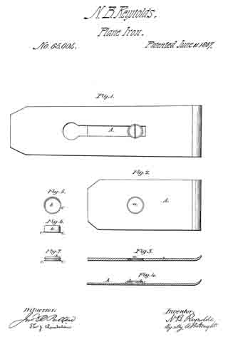
Figure I represents at view from the back of the plane-iron, showing the slot therein and the bolt passing through it into the cap.
Figure 2 represents a cap with a hole punched through it for the reception of the button which afterwards forms the swell, projection, or nut for the screw-bolt to take into.
Figure 3 represents a section through the cap, and showing the countersinking of the hole that is to receive the button.
Figure 4 represents a section through the cap after the button or swell is fastened thereto.
Figures 5 and 6 show a top and edge view of one of the buttons before it is inserted in the hole in the cap.
Figure 6 shows the form of the swell, button, projection, or nut after it has been riveted in the hole in the cap.
Similar letters of reference, where they occur in the several separate figures, denote like parts in all the drawings.
I am aware that a swell or projection has been proposed on the cap of a plane-iron as a substitute for the ordinary loose nut heretofore used. I do not claim the swell or projection. My invention consists in the manner or means of producing this projection, which I do in a very cheap and very durable manner, without rolling down the metal or heat-welding it.
To enable others skilled in the art to make and use my invention, I will proceed to describe the same with reference to the drawings.
At manufacturing establishments where boilers are made are to be found and procured at very cheap rates, and of the very finest quality of iron, any quantity of burrs or buttons that are punched out of the plates of which the boilers are made for rnaking rivet holes. These burrs or buttons can be procured at a rate but little above that of old iron, and are therefore very cheap, whilst they have the form, body, and flange or fin that peculiarly fits them for my purpose.
The cap A I propose to make of steel, and a hole, a, having been punched through, it is then countersunk or reamed out at each side of the plate or cap, as shown more distinctly in fig. 3. I then take one of the burrs or buttons 6 and insert it in the hole a in the cap. The fin or flange c which is on the burr or button, and left there by the punch that drove it out of the boiler-plate, fits into the countersink on one side of the hole, and the burr or button projects through and beyond the other face of the cap. In this position the cap and burr are placed under a drop-die, one blow of which rivets the button or burr in the hole, and it is afterwards dressed up to the proper shape or form for entering the slot in the plane-iron, and for preventing the cap from turning on the plane-iron, whilst it can move longitudinally of it. When the riveting on of the button is accomplished, as explained, the burr or button will have assumed the form shown at fig. 7, and also in fig. 4, and be as immovably fixed thereto as though it were a part of the same metal with the cap itself.
As a matter of economy I should always use the burrs or buttons made by punching boiler-plates, yet I would regard it as my invention if these burrs were especially punched out for the purpose herein named.
Having thus fully described my invention, what I claim therein as new, and desire to secure by Letters Patent in forming a swell or projection on the cap of a plane-iron, is —
The method of construction substantially as described.
N. B. REYNOLDS.
Witnesses:
I. W. QUICK,
T. R. HUSSY.