
| PLEASE NOTE: The images presented on this page are of low resolution and, as a result, will not print out very well. If you wish to have higher resolution files then you may purchase them for only $2.95 per patent by using the "Buy Now" button below. All purchases are via PayPal. These files have all been cleaned up and digitally enhanced and are therefore suitable for printing, publication or framing. Each zip package contains all the images below (some packages may contain more), and purchased files can be downloaded immediately. |
United States Patent Office.
JAMES L. BESS AND ADAM HAGNY, OF KEOKUK, IOWA.
Letters Patent No. 67,157, dated July 30, 1867.
_________________
IMPROVEMENT IN PLANES FOR CUTTING BLIND-SLATS.
_________________
The Schedule referred to in these Letters Patent and making part of the same.
_________________
TO ALL WHOM IT MAY CONCERN:
Be it known that we, JAMES L. BESS and ADAM HAGNY, of Keokuk, in the county of Lee, and State of Iowa, have invented a new and useful Improvement in Planes for Cutting Blind-Slats; and we do hereby declare the following to be a full, clear, and exact description of the nature, construction, and operation of the same, reference being had to the accompanying drawings, which are made a part of this specification, and in which —
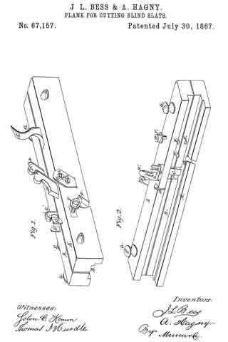
Figure 1 is a perspective view of our improved plane, showing the some in its operating position.
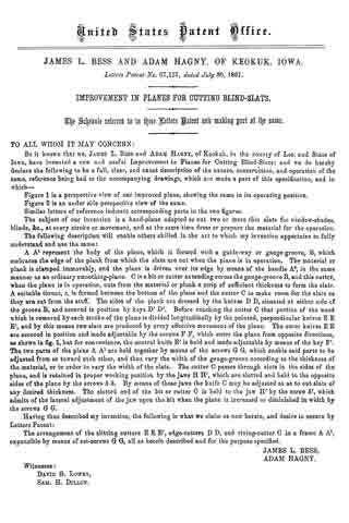
Figure 2 is an under side perspective view of the same.
Similar letters of reference indicate corresponding parts in the two figures.
The subject of our invention is a hand-plane adapted to out two or more thin slats for window-shades, blinds, &c., at every stroke or movement, and at the same time dress or prepare the material for the operation.
The following description will enable others skilled in the art to which my invention appertains to fully understand and use the same:
A A1 represent the body of the plane, which is formed with a guide-way or gauge groove, B, which embraces the edge of the plank from which the slats are out when the plane is in operation. The material or plank is clamped immovably, and the plane is driven over its edge by means of the handle A2, in the same manner as an ordinary smoothing-plane. C is a bit or cutter extending across the gauge-groove B, and this cutter, when the plane is in operation, cuts from the material or plank a strip of sufficient thickness to form the slats. A suitable throat, c, is formed between the bottom of the plane and the cutter C to make room for the slats as they are cut from the stuff. The sides of the plank are dressed by the knives D D, situated at either side of the groove B, and secured in position by keys D’ D’. Before reaching the cutter C that portion of the wood which is removed by each stroke of the plane is divided longitudinally by the pointed, perpendicular knives E E E’, and by this means two slats are produced by every effective movement of the plane. The outer knives E E are secured in position and made adjustable by the screws F F, which enter the plane from opposite directions, as shown in fig. 1, but for convenience, the central knife E’ is held and made adjustable by means of the key F’. The two parts of the plane A A1 are held together by means of the screws G G, which enable said parts to be adjusted from or toward each other, and thus vary the width of the gauge-groove according to the thickness of the material, or in order to vary the width of the slats. The cutter C passes through slots in tho sides of the plane, and is retained in proper working position by the jaws H H’, which are slotted and held to the opposite sides of the plane by the screws h h. By means of these jaws the knife C may be adjusted so as to cut slats of any desired thickness. The slotted end of the bit or cutter C is held to the jaw H’ by the screw h’, which admits of the lateral adjustment of the jaw upon the bit when the plane is increased or diminished in width by the screws G G.
Having thus described my invention, the following is what we claim as new herein, and desire to secure by Letters Patent:
The arrangement of the slitting cutters E E E’, edge-cutters D D, and riving-cutter C in a frame A A’, expansible by means of set-screws G’ G, all as herein described and for the purpose specified.
JAMES L. BESS,
ADAM HAGNY.
Witnesses:
DAVID G. LOWRY,
SAM. H. DILLON.