| PLEASE NOTE: The images presented on this page are of low resolution and, as a result, will not print out very well. If you wish to have higher resolution files then you may purchase them for only $2.95 per patent by using the "Buy Now" button below. All purchases are via PayPal. These files have all been cleaned up and digitally enhanced and are therefore suitable for printing, publication or framing. Each zip package contains all the images below (some packages may contain more), and purchased files can be downloaded immediately. |
UNITED STATES PATENT OFFICE.
_________________
MILLAGE MATHEW SMITH, OF STOCKDALE, TEXAS.
GAGE ATTACHMENT FOR BENCH-PLANES.
_________________
SPECIFICATION forming part of Letters Patent No. 661,559, dated November 13, 1900.
Application filed June 16, 1900. Serial No. 20,552. (No model.)
_________________
To all whom it may concern:
Be i t known that I, MILLAGE MATHEW SMITH, a citizen of the United States, residing at Stockdale, in the county of Wilson and State of Texas, haveinvented a new and useful Gage Attachment for Planes, of which the following is a specification.
The invention relates to improvements in gage attachments for planes.
The object of the present invention is to improve the construction of gages for planes and to provide a simple, inexpensive, and efficient device adapted to he readily applied to the stock of a plane and capable of being set at different angles to the face of the same to enable the edge or face of a board or piece to be accurately planed at the desired angle.
The invention consists in the construction and novel combination and arrangement of parts hereinafter fully described, illustrated in the accompanying drawings, and pointed out in the claims hereto appended.
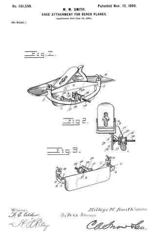
ln the drawings, Figure 1 is a perspective view of a plane provided with a gage attachment constructed in accordance with this invention. Fig. 2 is a transverse sectional view of the same, the plane being shown in elevation. Fig. 3 is a detail perspective view of the attachment, illustrating the manner of journaling the gage-plate on the supporting bar or piece.
Like numerals of reference designate corresponding parts in all the figures of the drawings.
1 designates a curved supporting har or piece arranged at one side of a plane 2 and extending downward and outward from the stock thereof and provided at its ends with clamps 3, consisting of upper perforated ears 4 and lower jaws 5, which are extended and provided with bearings 6 for the reception of journals or pintles 7 of a gage-plate 8. The clamps are adapted to engage the front and rear portions of the stock of the plane at one side thereof, and the upper perforated ears are threaded for the reception of screws 9, which are adapted to clamp the upper face of the stock of the plane at the inner face of the adjacent side or flange thereof, whereby the attachment is secureiy fastened to the stock.
The gage-plate 8, which is adapted to be arranged at different angles to the lower face of the plane to form a guide, is provided at its ends with the pintles 7, which are extended longitudinally from it and which are retained in the said bearings 6 by the stock when the attachment is clamped thereon, and they permit the gage-plate to swing inward and outward to and from the curved supporting piece or bar, which is extended outward and downward beyond the side of the plane, as clearly illustrated in Fig. 2.
The adjustment of the gage-plate is effected by means of a screw 10, pivoted to the said gage-plate at the outer face thereof and extending through an opening 11 of an ear 12, which is located centrally of the supporting bar or piece and which extends upward therefrom. The inner end or head of the screw is provided with a perforation for the reception of a pivot 13, which passes through a pair of perforated ears 14, extending outward from the center of the gage-plate. The adjusting-screw receives inner and outer nuts 15 and 16, located at opposite sides of the projecting portion or ear 12 of the supporting-piece and adapted to be adjusted to move the gage-plate inward and outward and capable of clamping the said ear 12, whereby the gage-plate is securely held at any adjustment. The supporting bar or piece 1 is provided with an upwardly-extending guide 17, located at a point between the adjusting device and one end of the supporting bar or piece and receiving a graduated bar or arm 18, and the latter is pivoted at its inner end between a pair of ears or lugs 19. The ears or lugs 19, which extend outward from the gage-plate and which are preferably formed integral with the same, are perforated for the reception of the pivot 20 of the graduated arm or bar. The graduated arm or bar will enable the gage-plate to be accurately set at the desired angle.
It will be seen that the device is exceedingly simple and inexpensive in construction, that it is adapted to be readily applied to a plane, and that it is capable of being readiiy set at the desired angle for enabling an edge or a face of a board to be accurately planed.
It will also be apparent that the gage-plate is detachably mounted on the supporting bar or piece and that the clamps which engage the stock of the plane and which secure the attachment to the same also operate to retain the journals or pintles of the gage-plate in the bearings of the supporting bar or piece.
What is claimed is —
1. In a device of the class described, the combination with a plane, of a gage-plate provided with pintles or journals, a supporting bar or piece having clamps for engaging the plane and provided in their engaging faces with open bearings receiving the journals or pintles of the gage-plate, said plane fitting over the open bearings and retaining the pintles or journals therein, and an ajusting device connecting the gage-plate with the supporting bar or piece, substantially as described.
2. In a device of the class described, the combination with a plane, of a gage-plate provided with pintles or pivots, a supporting bar or piece provided with clamps composed of lower jaws fitting against the plane and provided with open bearings receiving the pivots or pintles, the plane being arranged over the open bearings, whereby the gage-plate is removably secured to the supporting bar or piece by the engagement of the clamps with the plane, and clam ping-screws located above the said jaws and cooperating with the same, and an adjusting device connecting the gage-plate and the supporting-piece, substantially as described.
3. A gage attachment comprising a supporting bar or piece provided with clamps, a hinged gage-plate, an adjusting-screw pivoted at its inner end to the gage-plate and extending outward through an opening of the supporting bar or piece, nuts mounted on the adjusting-screw and located at the inner and outer sides of the supporting bar or piece, and a graduated bar or arm extending from the gage-plate and passing through a guide of the supporting bar or piece and arranged approximately parallel with the adjusting-screw, substantially as described.
In testimony that I claim the foregoing as my own I have hereto affixed my signature in the presence of two witnesses.
MILLAGE MATHEW SMITH.
Witnesses:
M. S. McGEE,
W. W. YOUNG.


