
| PLEASE NOTE: The images presented on this page are of low resolution and, as a result, will not print out very well. If you wish to have higher resolution files then you may purchase them for only $2.95 per patent by using the "Buy Now" button below. All purchases are via PayPal. These files have all been cleaned up and digitally enhanced and are therefore suitable for printing, publication or framing. Each zip package contains all the images below (some packages may contain more), and purchased files can be downloaded immediately. |
United States Patent Office.
G. D. SPOONER, OF RUTLAND, AND L. N. JOHNSON, OF BRANDON, VERMONT
Letters Patent No. 67,458, dated August 6, 1867.
_________________
IMPROVEMENT IN CARPENTERS’ PLANES.
_________________
The Schedule referred to in these Letters Patent and making part of the same.
_________________
TO ALL WHOM IT MAY CONCERN:
Be it known that We, G. D. SPOONER, of Rutland, and L. N. JOHNSON, of Brandon, both in the county of Rutland, and in the State of Vermont, have invented a new and useful improvement in Planes; and we do hereby declare that the following is a full, clear, and exact description thereof, which will enable those skilled in the art to make and use the same, reference being had to the accompanying drawing, forming part of this specification, in which drawing —
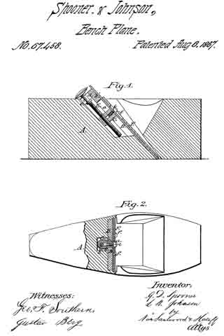
Figure 1 represents a longitudinal vertical section of the invention.
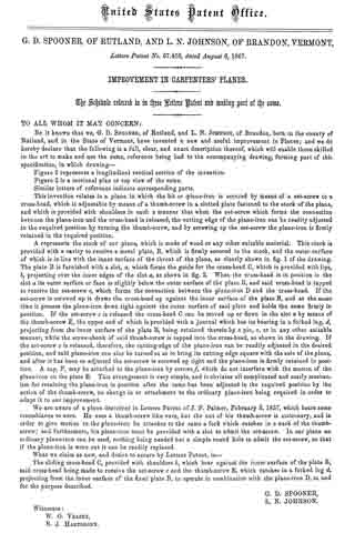
Figure 2 is a sectional plan or top view of the same.
Similar letters of reference indicate corresponding parts.
This invention relates to a plane in which the bit or plane-iron is secured by means of a set-screw to a cross-head, which is adjustable by means of a thumb-screw in a slotted plate fastened to the stock of the plane, and which is provided with shoulders in such a manner that when the set-screw which forms the connection between the plane-iron and the cross-head is released, the cutting edge of the plane-iron can be readily adjusted in the required position by turning the thumb-screw, and by screwing up the set-screw the plane-iron is firmly retained in the required position.
A represents the stock of our plane, which is made of wood or any other suitable material. This stock is provided with a cavity to receive a metal plate, B, which is firmly secured to the stock, and the outer surface of which is in line with the inner surface of the throat of the plane, as clearly shown in fig. 1 of the drawing. The plate B is furnished with a slot, a, which forms the guide for the cross-head C, which is provided with lips, b, projecting over the inner edges of the slot a, as shown in fig. 2. When the cross-bead is in position in the slot it its outer surface or face is slightly below the outer surface ofthe plate B, and said cross-head is tapped to receive the set-screw c, which forms the connection between the plane-iron D and the cross-head. If the set-screw is screwed up it draws the cross-head up against the inner surface of the plate B, and at the same time it presses the plane-iron down tight against the outer surface of said plate and holds the same firmly in position. If the set-screw c is released the cross-head C can be moved up or down in the slot a by means of the thumb-screw E, the upper end of which is provided with a journal which has its bearing in a forked lug, d, projecting from the inner surface of the plate B, being retained therein by a pin, e, or in any other suitable manner, while the screw-shank of said thumb-screw is tapped into the cross-head, as shown in the drawing. If the set-screw c is released, therefore, the cutting-edge of the plane-iron can be readily adjusted in the desired position, and said plane-iron can also be turned so as to bring its cutting edge square with the sole of the plane, and after it has been so adjusted the set-screw is screwed up tight and the plane-iron is firmly retained in position. A cap, F, may be attached to the plane-iron by screws f which do not interfere with the motion of the plane-iron on the plate B. This arrangement is very simple, and it obviates all complicated and costly mechanism for retaining the plane-iron in position after the same has been adjusted in the required position by the action of the thumb-screw, no change in or attachment to the ordinary plane-iron being required in order to adapt it to our improvement.
We are aware of a plane described in Letters Patent of J. F. Palmer, February 3, 1857, which bears some resemblance to ours. He uses a thumb-screw like ours, but the nut of his thumb-screw is stationary, and in order to give motion to the plane-iron he attaches to the same a fork which catches in a neck of the thumb-screw; and furthermore, his plane-iron must be provided with a slot to admit the set-screw. ln our plane an ordinary plane-iron can be used, nothing being needed but a simple round hole to admit the set-screw, so that if the plane-iron is worn out it can be readily replaced.
What we claim as new, and desire to secure by Letters Patent, is —
The sliding cross-head C, provided with shoulders b, which bear against the inner surface of the plate B, said cross-head being made to receive the set-screw c and the thumb-screw E, which catches in a forked lug d, projecting from the inner surface of the fixed plate B, to operate in combination with the plane-iron D, as and for the purpose described.
G. D. SPOONER,
L. N. JOHNSON.
Witnesses:
W. G. VEAZEY,
E. J. HARTSHORN.