
| PLEASE NOTE: The images presented on this page are of low resolution and, as a result, will not print out very well. If you wish to have higher resolution files then you may purchase them for only $2.95 per patent by using the "Buy Now" button below. All purchases are via PayPal. These files have all been cleaned up and digitally enhanced and are therefore suitable for printing, publication or framing. Each zip package contains all the images below (some packages may contain more), and purchased files can be downloaded immediately. |
UNITED STATES PATENT OFFICE.
_________________
ALBERT F. SCHADE, OF NEW BRITAIN, CONNECTICUT, ASSIGNOR TO
STANLEY RULE AND LEVEL COMPANY, OF NEW BRITAIN, CONNECTICUT.
CARPENTER’S ROUTER.
_________________
SPECIFICATION forming part of Letters Patent No. 685,411, dated October 29, 1901.
Application filed March 6, 1901. Serial No. 50,130. (No model.)
_________________
To all whom it may concern:
Be it known that I, ALBERT F. SCHADE, a citizen of the United States, residing in New Britain, in the county of Hartford and State of Connecticut, have invented certain new and useful Improvements in Carpenters’ Routers, of which the following is a specification.
My invention relates to improvements in carpenters’ routers; and the object of my improvement is to provide simple and efficient means for adjusting the cutter.
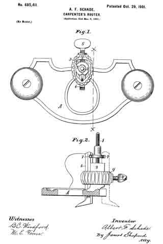
In the accompanying drawings, Figure 1 is a plan view of my router; and Fig. 2 is a sectional side elevation, the bed plate or frame being in vertical section on the line x x of Fig. 1.
The bed plate or frame A, tool-post 3, yoke 4, and set-screw 5 are of an ordinary and well-known construction. The cutter 6 is also of an old form, excepting as I provide a recess or notch 7 in its rear side near its upper end. In the center of the tool-post 3 and projecting upwardly therefrom is the adjusting-screw 8, rigidly and permanently affixed thereto or formed thereon, so as to constitute an immovable part thereof. Upon this screw is the adjusting-nut 9, preferably having a roughened or knurled edge for convenience of manipulation. This nut is of a diameter so large as to project into the path of the upper end of the cutter 6, whereby the adjusting-nut 9 and the cutter 6 may be assembled with the edge of the nut projecting into the recess or notch 7 in the cutter 6, as best shown in Fig. 2.
It will be readily seen that the cutter may be adjusted either up or down by turning the adjusting-nut 9; also, that the parts may be assembled when desired with the adjusting-nut above the notch in the cutter or wholly removed, so that the cutter may be used without any adjusting mechanism. The cutter 6 may also be placed in the reverse position on the back side of the post, as indicated by broken lines in Fig. 2, and the same adjusting mechanism is adapted for use with the cutter in this reversed position. The construction is simple and inexpensive, and the improved device is very convenient for effecting a fine adjustment, while it in no way interferes with any of the ordinary uses of the router.
I claim as my invention —
The combination of the bed-plate, the double-faced tool-post, projecting upwardly above the said bed, the cutter fitted to slide vertically cn the sides of the said tool-post, means for confining the said cutter in place on the said tool-post, the adjusting-screw 8, centrally mounted in the upper end of the said tool-post and projecting upwardly therefrom, and the adjusting-nut 9, mounted on the said adjusting-screw and operatively connected with the upper end of the said cutter, whereby the said adjusting mechanism may be used when the cutter is placed on either side of the said tool-post, substantially as described.
ALBERT F. SCHADE.
Witnesses:
H. S. WALTER,
E. G. HOFFMAN.