
| PLEASE NOTE: The images presented on this page are of low resolution and, as a result, will not print out very well. If you wish to have higher resolution files then you may purchase them for only $2.95 per patent by using the "Buy Now" button below. All purchases are via PayPal. These files have all been cleaned up and digitally enhanced and are therefore suitable for printing, publication or framing. Each zip package contains all the images below (some packages may contain more), and purchased files can be downloaded immediately. |
United States Patent Office.
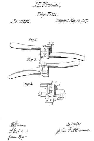
JOHN E. PLUMMER, OF BINGHAMTON, NEW YORK.
Letters Patent No. 70,894, dated November 12, 1867.
_________________
IMPROVED EDGE-PLANE.
_________________
The Schedule referred to in these Letters Patent and making part of the same.
_________________
TO ALL WHOM IT MAY CONCERN:
Be it known that I, JOHN E. PLUMMER, of Binghamton, in the county of Broome, and State of New York, have invented a new and useful improvement on Edge-Planes for trimming the edges of boots and shoes; and I do hereby declare that the following is a full, clear, and exact description of the construction and operation of the same, reference being had to the accompanying drawings, making a part of this specification, in which —
Figures 1 and 2 are perspective views, showing the concave and convex cutters.
Figure 3 represents the stock with the cutter-guard and throat detached.
Similar letters of reference indicate corresponding parts in each figure.
The object of my improvement is to construct a “reversible-edge plane” for trimming the soles of boots and shoes, which shall possess all the qualities requisite to accomplish the object with greater facility and ease, and at the same time to require less attention to keep it in order, than those in common use.
The nature of my invention consists in arranging a cutter on each side and in the centre of a stock, with a handle at each end. One of the cutters is designed for trimming the fore part of the sole, and the other for the “shank,” or that part under the instep, thereby combining in the same tool a cutter for the front or convex edges, and another for the “shank,” or concave edges of the sole.
It also consists in the simplicity of its construction and the adaptability of its form to accomplish the object designed.
I construct the stock A and the handles of cast brass, iron, or other suitable material. In the centre of the stock, I make projections B B on each side of the handles for the cutters C C, which are held in their places by the guard-plates D D, which are grooved to correspond with those in the stock, as represented in fig. 3, letters E E. The lower ends of said guard-plates are notched to fit into the shanks of the handles. The upper ends F F project above the face of the cutters, and are chamfered to work between the sole and the “uppers” of the boot or shoe, thereby protecting the work from injury. I then drill a hole, G, through the plate and into the stock, tap it, and enter the screw, but before turning it fully down, and while the guard-plate is still slightly loose, I enter the cutter into the grooves E E, and turn up the screw, which holds it securely in position. The throat H of the plane is made of steel, bent at right angles to the face, fitted between the guard and stock-back of the cutters, and the arm into a recess, I, held in place by a screw. The hole in the arm, through which said screw passes into the stock, is slightly elongated, for the purpose of graduating the shaving of the cutter. The stock A is chamfered down under the cutter and throat for the purpose of giving clearance to the shavings. The handles of the plane are slightly curved, and connect with the stock opposite, and their upper sides nearly flush with, the face of the plane or cutter on each side, so that when trimming the concave edges of the sole under the instep the opposite handle will not interfere with the work. One of the cutters is made straight for the purpose of trimming the convex edges of the sole. The other is curved to correspond to the concave edges under the instep.
The convex or fore part of the sole requires a “finer set” of the cutter than that of the shank or concave part, consequently manufacturers often use two instruments to accomplish the object rather than be constantly changing the “set” of the tool.
I am aware that there are many other arrangements for a similar purpose, but, so far as I know, there are none involving the combinations of my improvement. I therefore disclaim all interference with others, and confine myself to the novel features of my improvement.
Having thus described my invention, what I claim, and desire to secure by Letters Patent, is —
The construction and use of a “reversible-edge plane,” substantially as described and represented for the purpose set forth.
JOHN E. PLUMMER.
Witnesses:
A. E. ANDREWS,
JAMES FLYNN.