
| PLEASE NOTE: The images presented on this page are of low resolution and, as a result, will not print out very well. If you wish to have higher resolution files then you may purchase them for only $2.95 per patent by using the "Buy Now" button below. All purchases are via PayPal. These files have all been cleaned up and digitally enhanced and are therefore suitable for printing, publication or framing. Each zip package contains all the images below (some packages may contain more), and purchased files can be downloaded immediately. |
UNITED STATES PATENT OFFICE.
_________________
JOHN E. McCAULEY, OF SPRINGFIELD, OHIO, ASSIGNOR OF ONE-HALF
TO WILLIAM D. BAYLEY, OF SPRINGFIELD, OHIO.
HAND-TOOL.
_________________
SPECIFICATION forming part of Letters Patent No. 751,671, dated February 9, 1904.
Application filed June 15, 1903. Serial No. 161,488. (No model.)
_________________
To all whom it may concern:
Be it known that I, JOHN E. McCAULEY, a citizen of the United States, residing at Springfield, in the county of Clark and State of Ohio, have invented certain new and useful Improvements in Hand-Tools, of which the following is a specification.
My invention relates to hand-tools, and more particularly to hand-planers for planing out the semicircular groove in core-boxes, but may be used in planing like grooves in any article.
The object of my invention is to provide a hand-planer of such construction that at each operation of the tool the cutter will be turned to take an additional cut in such manner that when the operation is complete a semicircular groove will be formed, and a further object is to provide means to adjust the feed of the cutter.
A further object is to provide a sliding frame that can be adjusted to the size of the article to be planed and to elastically hold said frame in engagement with the article.
With these and other objects in view my invention consists of the constructions and combinations hereinafter described, and set forth in the claims.
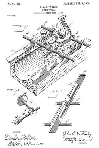
In the accompanying drawings, which form a part of this specification, Figure 1 represents a planer embodying my invention. Fig. 2 is a detail of the feed device, and Fig. 3 is a detail of one of the side frames with a tension-cushion thereon.
Like parts are represented by similar letters of reference in the several views.
In the drawings, a represents a slide on one side of the frame adapted to engage the top and one side of the article to be planed, and a’ represents another slide on the other side of the frame adapted to rest on the top of the article to be planed and has secured thereto a spring-cushion, which I have shown in the form of an elongated loop a2, adapted to engage the other side of the article to be planed. Cross-rods a3 and a4 rest in bearings on the slides, and clamping-plates a5, having thumb-screws a6 extending through same into screw-threaded perforations in the slides, are provided, so that the slides can be moved to and from each other and adjusted to the size of the article to be planed and fixed in their adjusted positions by said thumb-screws. This adjustment is made so that the spring-cushion a2 will bear against one side of the article to be planed while the operator holds the planer firmly against the opposite side.
A frame b, having perforations through which the cross-rods a3 and a4 extend, is movable longitudinally on said rods and is held in its adjusted position by a set-screw b’. A shaft b2, longitudinally disposed in the line of travel of the planer, is provided with a head b3, having a slot therein, through which a cutter-bar b4 extends at right angles to said shaft and is secured in place by a set-screw b5. Said cutter-bar has a cutting edge extending from said head to and including the outer end thereof. The shaft b2 is journaled in a hanger b6, the upper portion of which is screw-threaded and extends through an opening in the frame b and is tightened in place by a thumb-nut b7. A shaft b8, journaled in the frame b at an angle to the shaft b2, has a ratchet-wheel b9 fixed thereon, and a pair of worm-gears b10, fixed on said shafts, transmit motion from one to the other.
Through an opening in the frame b a handle c is journaled on the cross-rod a4, and on a forwardly and upwardly extending arm c’ of said handle there is a projection c2, which engages the frame b and limits the forward rocking movement of the handle, while a set-screw c3 is employed to adjustably limit the rearward rocking movement of said handle. A pawl c4, pivoted to the arm c’ of the handle, is adapted to engage the ratchet-wheel b9. The construction is such that when the handle is grasped to push the planer forward the handle will rock forward until the stop c2 engages the frame and the pawl will engage and move the ratchet to an extent permitted by this rocking movement, and the cutter-bar will thereby be turned to take an additional cut when the planer is moved forward. By turning the set-screw c3 the extent of the rocking movement can be varied and the feed of the cutter adjusted.
To operate the planer, the slides are adjusted to the article to be planed, as herein-before described, and the frame b is adjusted on the cross-rods so that the shaft which carries the cutter-bar is in line with the longitudinal center of the groove to be cut, with the cutter-bar in a horizontal position at right angles thereto. Then grasping the handle and pushing the planer forward the initial rocking movement will set the cutter in position so that in the forward movement of the planer it will take a cut and at each succeeding forward movement the cutter will be turned sufficiently to take an additional cut and the continued operation of the planer will form a semicircular groove. In practice it may be found convenient after finishing one-half of the groove to reverse the position of the planer, reset the cutter to horizontal position, and plane out the other half from the top of the article being planed in like manner as the first half, or the operator may first rough out the groove with another tool and then finish with a planer embodying my invention.
Having thus described my invention, I claim —
1. In a hand-planer, a frame having laterally-movable slides adapted to elastically contact with the respective sides of the article to be planed, means to fix said slides in their relation to each other, a cutter journaled in said frame, and means to partially rotate said cutter transversely to the line of travel of said planer at each operation of the planer, substantially as specified.
2. In a hand-planer, a frame having laterally-movable slides adapted to engage the respective sides of the article to be planed, one of which has a projecting portion and the other a spring-cushion, said projection and cushion being adapted to contact with the respective sides of the article to be planed, means to fix said slides in their relation to each other, a cutter journaled in said frame, and means to partially rotate said cutter transversely to the line of travel of said planer at each operation of the planer, substantially as specified.
3. In a hand-planer, a frame having laterally-movable slides adapted to engage the respective sides of the article to be planed, one of which has a projection and the other a spring-cushion, said projection and cushion being adapted to contact with the respective sides of the article to be planed, means to fix the relative position of said slides, a laterally-mow able portion of said frame and means to fix its position, a shaft journaled in said portion longitudinally in the line of travel of the planer, a cutter-bar and a head on said shaft adapted to hold said cutter at right angles to said shaft, another shaft journaled in said portion having a ratchet-wheel thereon and a gear connection with said first-named shaft, an operating-hawdle pivoted to rock on said portion, means to adjust and limit said rocking movement, a pawl pivoted on said handle and adapted to engage said ratchet-wheel, substantially as specified.
In testimony whereof I have hereunto set my hand this 2d day of May, A. D. 1903.
JOHN E. McCAULEY.
Witnesses:
PERCY NORTON,
OLIVER H. MILLER.