
| PLEASE NOTE: The images presented on this page are of low resolution and, as a result, will not print out very well. If you wish to have higher resolution files then you may purchase them for only $2.95 per patent by using the "Buy Now" button below. All purchases are via PayPal. These files have all been cleaned up and digitally enhanced and are therefore suitable for printing, publication or framing. Each zip package contains all the images below (some packages may contain more), and purchased files can be downloaded immediately. |
UNITED STATES PATENT OFFICE.
_________________
ALBERT F. SCHADE, OF NEW BRITAIN, CONNECTICUT, ASSIGNOR TO
STANLEY RULE & LEVEL COMPANY OF NEW BRITAIN CONNECTICUT,
A CORPORATION OF CONNECTIOUT.
PLANE.
_________________
SPECIFICATION forming part of Letters Patent No. 758,698, dated May 3, 1904.
Application filed January 16, 1902. Serial No. 89,958. (No model.)
_________________
To all whom it may concern:
Be it known that I, ALBERT F. SCHADE, a citizen of the United States, residing at New Britain, county of Hartford, State of Connecticut, have invented certain new and useful Improvements in Planes, of which the following is a full, clear, and exact description.
My invention relates to improvements in the construction of planes.
The object of my invention is to provide a simple, inexpensive, and effective device for securing in place the means whereby the position of the cap of the plane is determined, as will be understood from the following description, taken in connection with the accompanying drawings.
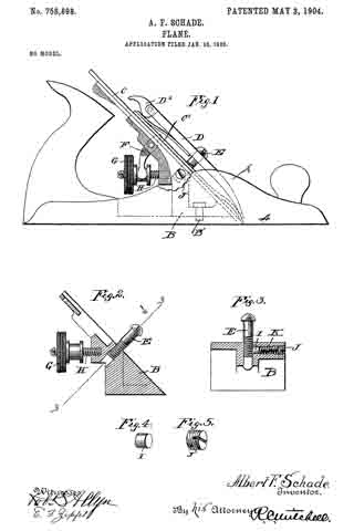
In the drawings, Figure 1 is a side elevation of a plane with one side partly broken away to show a detail of construction. Fig. 2 is a longitudinal section of a portion of the plane, showing details of construction. Fig. 3 is a section on the line 3 3, Fig. 2. Figs. 4 and 5 are views of details of construction.
The plane which I have chosen to here describe is an iron plane, in which A is the bottom, and A’ is a side flange.
C is what is commonly termed the “frog,” which is secured by the screw B’ to the bottom between the side flanges and presents an inclined upper surface leading down to the slot in the bottom or base through which the plane-iron C projects. In this type of plane, C’ is the plane-iron cap, the two parts thus forming a plane-iron of double thickness. The iron C furnishes the cutting edge.
D is what is termed the “cap.” In the particular construction shown this cap is provided with a cam D’.
E is what may be termed a “cap-screw” or “holder.” The screw E is ordinarily in the form of a headed screw taking into a tapped hole in the frog B.
The holder E is seldom if ever adjusted after it has been secured in its proper position, and it is desirable to have it snugly retained in position, so that it will not work loose and thus disturb the adjustment of the cap and associated parts. Should the parts become loose, they would chatter and would not properly perform their intended functions. It is desirable not to have a permanent connection in order that in the event of an emergency a new holder or screw E may be inserted and also in order that, if desirable, the same may be adjusted. In case the cap should become broken or lost a new cap must be provided, and if it should happen that the new cap should vary slightly in dimensions from the original cap the holder would have to be adjusted. For that reason it will be seen that while adjustment of the cap-screw is not the common thing, it is, nevertheless, a desirable incident.
F is a lever or Y adjustment pivoted to the frog B, one end of which is adapted to engage with the plane-iron C, the other end being engaged by an adjusting-nut G, movable on a screw or post H, also carried by the frog. The plane-iron may be advanced or retracted relatively to the bottom of the plane by means of the adjusting-nut G, which operates the lever F, engaging with the pl ane-iron and regulating the depth of the cutting edge in the usual manner.
My invention does not relate generally to the construction of the plane and is therefore not limited to any special type of plane, but relates more particularly to an adjustable holding device for the said cap-screw and comprises a means adapted to frictionally bear against the said screw to prevent its turning. This means comprises a shoe I, carried in a hole or passage in the side of the frog B, which hole or passage at its outer end may be screw-threaded to carry an adjusting-screw J. Between the adjusting-screw J and the shoe I is a spring K. The construction and arrangement of the parts are best seen in Fig. 3, in which it will be seen the shoe bears directly against the side of the cap-screw E and with a pressure depending upon the adjustment of the screw J. In practice this has been found sufficient to properly hold the cap-screw in the desired position, and yet it does not so hold it that it cannot be adjusted. It provides a simple, inexpensive, and effective means for accomplishing the desired end, and in operation will not batter or otherwise injure the screw-threads of the cap-screw E. The frog is unseated when it is desired to adjust the screw J. When the cap-screw E is locked by the adjusting-screw J and the frog is seated in the body portion, it is impossible for the screw J to work out and be lost, since it is held in place by the flange A’, which substantially covers the end thereof.
What I claim, and desire to secure by Letters Patent, is —
In a plane the combination of a body having side flanges and a removable frog secured thereto between said flanges, a cap-screw seated in said frog, an adjusting-screw operating in the side of the frog to clamp said cap-screw, the head of said adjusting-screw being held from extraction by one of the side flanges, substantially as described.
ALBERT F. SCHADE.
Witnesses:
A. W. STANLEY,
C. S. HODGE.