
| PLEASE NOTE: The images presented on this page are of low resolution and, as a result, will not print out very well. If you wish to have higher resolution files then you may purchase them for only $2.95 per patent by using the "Buy Now" button below. All purchases are via PayPal. These files have all been cleaned up and digitally enhanced and are therefore suitable for printing, publication or framing. Each zip package contains all the images below (some packages may contain more), and purchased files can be downloaded immediately. |

UNITED STATES PATENT OFFICE.
_________________
HENRY PLANTE, OF NEW YORK, N. Y.
HOUSE-CARPENTER’S TOOL.
_________________
SPECIFICATION forming part of Letters Patent No. 760,245, dated May 17, 1904.
Application filed June 17, 1903. Serial No. 161,823. (No model.)
_________________
To all whom it may concern:
Be it lrnown that I, HENRY PLANTE, a citizen of the United States, and a resident of the city of New York, borough of Manhattan, in the county and State of New York, have invented a new and Improved House-Carpenter’s Tool, of which the following is a full, clear, and exact description.
This invention relates to an improvelnent on my prior patent for a gage granted February 23, 1886, No. 336,742.
The object of the present invention is to enlarge the capacity of the gage illustrated in my previous patent so as to render the improved tool capable of use in a great number of operations necessary in house-carpentry — for example, in the planing of door-jambs to enable the doors to fit properly, the measurement and cutting out of panels to be inserted into the door, and other parts of the house-fittings and in the use of bead-planes generally, all of which functions are in addition to those embodied in the gage as above disclosed.
This specification is an exact description of one example of my invention, while the claims define the actual scope thereof.
Reference is to be had to the accompanying drawings, forming a part of this specification, in which similar characters of reference indicate corresponding parts in all the views.
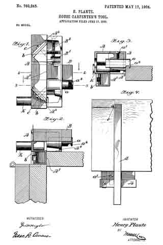
Figure 1 is an inverted plan view of the device. Fig. 2 is a section on the line 2 2 of Fig. 1. Fig. 3 is a section on the line 3 3 of Fig. 1, and Fig. 4 is a top plan view illustrating the use of the panel-cutting attachment.
The body A of the gage is provided with the slide B and the tube K, both before employed.
B’ indicates a spring-finger for exerting a frictional tension on the slide B, and B2 indicates a set-screw for adjusting this pressure.
a indicates a tube formed, preferably, of steel and fitted transversely in the body A, as shown best in Fig. 3. a’ indicates a set-screw for adjustably holding the tube a in place. Said tube a is formed with a curved notch a2, passing transversely therethrough immediately adjacent to its end and forming two knife-edges at opposite sides of the tube, enabling it to cut away the wood or other material at a corner therein and form the bead, as indicated in Fig. 3. As shown best in Fig. 1, the tube has a slot a3 formed therein and extending outward from the slot a2 to the end of the tube, this latter slot forming opposite cutting edges, enabling the end of the tube to cut down into the work, as illustrated. By means of this device the tool may be readily employed as a bead-plane, and this will be a great advantage to carpenters, since the operation of beading is very commonly resorted to in house-fitting.
The tool is formed with a longitudinally-extending groove A2 in one of its corners. this groove being in the form of a large rabbet, so as to receive the corner of the jamb of the door, as indicated in Fig. 2, and to allow the face A3 to bear against the jamb. This face A3 is formed with two notches A4 thereon, and in said notches are held the planing-knives b, which are securely adjusted by means of screws c, all of which will be understood from the drawings. These knives are disposed oppositely to each other, so that in reciprocating the tools over the work the knives will alternately be active and also so as to enable the extremities of the jamb both at the top and bottom of the door to be reached by the knives during the planing operation. In this connection it should be understood that the door-step and the top of the door-frame will prevent the plane from being moved completely over the extremities of the jamb; but this difficulty is minimized by providing the two knives oppositely disposed and located, respectively, adjacent to the ends of the tool.
Fig. 4 shows the application of the panel-cutting attachment. In this instance the slide B of Figs. 1 and 2 is removed and a long slide or arm d is used in its stead, this arm having at its outer end a knife e. The arm d is adjusted on the tool so as to place the knife c in the desired position, and then by drawing the blade e along the veneer of which the panel is formed the panel may be properly cut. If necessary, the panel may be reversed and the incision made with the blade e on both sides, these incisions meeting to form the complete cut in the veneer.
In view of my prior patent the use and advantages of my invention will be fuliy understood by persons skilled in the art.
Various changes in the form, proportions, and minor details of my invention may be resorted to at will without departing from the spirit and scope thereof. Hence I consider myself entitled to all such variations as may lie within the intent of my claims.
Having thus described my invention, I claim as new and desire to secure by Letters Patent —
1. A carpenter’s tool, comprising a tube having a transverse cut extending through the walls of the tube and a longitudinal slot extending from the cut-out to the end of the tube to form a beading-plane.
2. A carpenter’s tool, comprising a body having an opening therein, and a tube adjustably mounted in said opening, the tube having a transversely-extending cut in the walls thereof and a longitudinal slot extending from the cut-out to the end of the tube, forming a beading-plane, for the purpose specified.
3. A carpenter’s tool, comprising a body having a planing-surface thereon, a planing-knife juxtaposed to said body, and a tube adjustably mounted in the body and having a transversely-extending cut therein forming a beading-plane.
4. A carpenter’s tool, comprising a body having a planing-surface thereon, two oppositely-disposed planing-knives juxtaposed to said surface and located respectively adjacent to the ends thereof, and an adjustable tube mounted in the body and having a transverse cut therein forming a beading-plane.
5. A carpenter’s tool, comprising a body having a longitudinally-extending groove in one of its corners, a planing-blade mounted on the body and lying with its edge coincident to one of the side walls of said groove, the body also having a transverse groove therein, a slide adjustably mounted in said groove and having a marking device thereon, means for adjustably holding the slide, the body also having an opening extending therethrough, a tube fitted in said opening and open throughout its ends, the tube having a transverse cut extending through its walls at one end portion, and a longitudinal slot extending from the cut-out to the end of the tube, and means for removably holding the tube in place.
In testimony whereof I have signed my name to this speciiication in the presence of two subscribing witnesses.
HENRY PLANTE.
Witnesses:
JNO. M. RITTER,
H. T. BERNHARD.