
| PLEASE NOTE: The images presented on this page are of low resolution and, as a result, will not print out very well. If you wish to have higher resolution files then you may purchase them for only $2.95 per patent by using the "Buy Now" button below. All purchases are via PayPal. These files have all been cleaned up and digitally enhanced and are therefore suitable for printing, publication or framing. Each zip package contains all the images below (some packages may contain more), and purchased files can be downloaded immediately. |
UNITED STATES PATENT OFFICE.
_________________
McCLUER H. PARKER, OF LOS ANGELES, CALIFORNIA.
ROUTER-PLANE.
_________________
SPECIFICATION forming part of Letters Patent No. 761,097, dated May 31, 1904.
Application filed December 15, 1903. Serial No. 185,228. (No model.)
_________________
To all whom it may concern:
Be it known that I, McCLUER H. PARKER, a citizen of the United States, residing at Los Angeles, in the county of Los Angeles and State of California, have invented a new and useful Router-Plane, of which the following is a specification.
This invention relates to improvements in router-planes, and particularly to the adjusting and clamping of the cutting knife or bit.
The router-plane forming the present invention is particularly adapted for routing out seats for door butts or hinges and for cutting out for locks and strike-plates for the same. The plane is of value in cutting seats for other building hardware or material that requires inlaying.
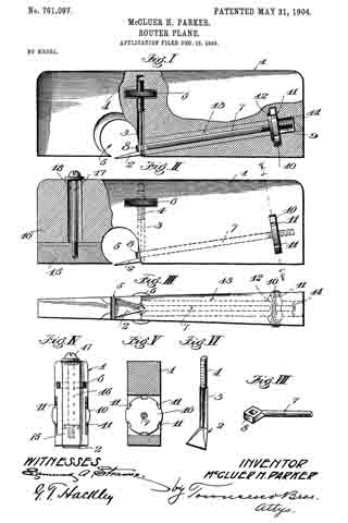
The accompanying drawings illustrate the invention, and referring to the same, Figure I is a side view of the router-plane with part of the stock broken away, showing the preferred construction. Fig. II is a side view of the router-plane, with part of the stock broken away, of another form. Fig. III is a bottom view of the form shown in Fig. I. Fig. IV is a view looking toward the nose of the form shown in Fig. II. Fig. V is a section on line V V, Fig. II. Fig. VI is a detail in perspective of the cutter or bit. Fig. VII isa detail in perspective of the clamping-rod.
1 designates the stock, which preferably tapers throughout its length, as shown, being wider at the heel than at the nose.
2 designates the cutting iron or bit, which is provided with a squared shank 3, the upper end of which is threaded, as at 4. The squared shank 3 is received by the stock of the plane in a square hole, and when in position the flat faces of the shank engage the flat faces of the hole to hold the shank from rotation relatively to the stock, the hole extending substantially at right angles to the bottom of the stock, and the cutting-iron 2 projects slightly downward and forward from the rear part of the throat 5 of the stock.
6 is a knurled thumb-nut which is mounted on the threaded shank 3, the stock 1 being slotted to receive the thumb-nut 6, and the edges of the nut protrude, as shown in Fig. III, so as to be readily grasped by the fingers in adjusting the cutting-iron.
7 is a clamping-bar having an eye 8, which is squared internally to receive the shank 3 of the cutting-iron, the shank 3 loosely fitting in the eye. The other end of the clamping-bar 7 is threaded, as at 9. and carries a locking-nut 10, the periphery of which is provided with square notches 11, which afford shoulders against which a tool may be struck-such, for instance, as a nail-set-to tighten the clamping-nut securely.
The stock 1 is slotted to receive the clamping-nut 10, and a washer 12 is provided within the stock 1, against which the locking-nut bears when screwed tight.
As shown, the clamping-bar extends from the rear of the throat 5 nearly to the heel of the plane and is inclined so as to bring the clamping-nut well above the bearing-face or bottom of the stock.
In the preferred form the stock 1 is made of a single piece of wood, and in order to put the clamping-bar in place in the stock the stock is drilled from the heel toward the throat with a hole of sufflcient diameter to allow of the passage through it of the eye 8, and a wooden sleeve 13, which is drilled centrally to receive the locking-bar 7, together with the locking-bar 7, is slipped into the hole in the stock from the heel, the sleeve before being inserted having had glue applied to its surface and the hole in the stock also having had glue applied to its surface, so that when the sleeve is in place in the stock the glue sets and the sleeve becomes practically part of the stock. A plug 14 is then glued into the stock to fill the end of the hole. Another form is shown in Fig. II, in which the lower part of the nose 15 is fastened to the upper part 16 by a tongue-and-groove joint, a tightening-screw 17 passing down through a wide slot 18 in the stock and screwing into the adjustable part 15. When the plane is of metal, it may preferably be constructed in this form and the sleeve 13 may be dispensed with, as the adjustable nose 15 may be moved forward or entirely removed from the stock to permit the locking-bar 7 to be slipped into place in the stock from the front, the hole in the stock in such cases being drilled of a size to just receive the shank of the locking-bar. After the locking-bar is in place the nose 15 may be fastened by tightening the screw 17.
When the lock-nut 10 is screwed up tight, it draws the locking-bar 7 to the rear and forces the shank 3 tightly against its squared seat in the stock 1, and the cutting-iron 2 is thus prevented from turning sidewise or from slipping up or down. To adjust the cutting-iron 2, the lock-nut 10 is loosened, which frees the shank 3, so that the nut 6 may be readily turned by the fingers to raise or lower the cutting-iron 2, and when it has been brought to the desired position the lock-nut 10 is again tightened, being easily forced very tightly into place by inserting a nail-set in a notch of the lock-nut and tapping the same.
I have found in practice that a plane constructed as herein set forth more than doubles the capacity of a mechanic in hinging doors and in doing other similar work and that the grade of work is also improved to a marked degree.
What I claim is —
1. A stock having a throat and having a hole extending substantially at right angles to the bottom of the stock, a cutting-iron having a shank lying in said hole, the shank and the part of the stock engaging therewith being formed with engaging parts to hold the shank from rotation, the shank having a threaded portion and a nut on the threaded portion for adjusting the cutting-iron, and means for clamping the shank.
2. A stock having a throat, and having a hole with a fiat face extending at substantially right angles to the bottom of the stock, a cutting-iron having a shank with a flat face lying in the hole, the shank having a threaded portion, and a nut on the threaded portion for adjusting the cutting-iron, and means for clamping the shank.
3. A stock having a throat, and having a hole with a flat face extending substantially at right angles to the bottom of the stock, a cutting-iron having a shank with a flat face lying in the hole, the shank having a threaded portion, a nut on the threaded portion for adjusting the cutting-iron, means for clamping the shank, and a clamping-bar having an eye through which the shank passes, the clamping-bar having a threaded portion, and a nut on the threaded portion for tightening the clamping-bar.
4. A stock, a cutting-iron having a squared shank threaded at one end, the shank lying within a square hole in the stock and substantially perpendicular to the bottom of the stock, a nut on the threaded portion of the shank within a slot in the stock, a clamping-bar having a squared eye which receives the shank of the cutting-iron, the clamping-bar having a threaded portion, and a nut on the threaded portion in a slot in the stock.
5. A stock, a cutting-iron having a squared shank threaded at one end, the shank lying within a square hole in the stock and substantially perpendicular to the bottom of the stock, a nut on the threaded portion of the shank within a slot in the stock, a clamping-bar having a squared eye which receives the shank of the cutting-iron, the clamping-bar having a threaded portion, and a nut on the threaded portion in a slot in the stock, said latter nut having a notched periphery.
6. A stock, a cutting-iron having a squared shank threaded at one end, the shank lying within a square hole in the stock and substantially perpendicular to the bottom of the stock, a nut on the threaded portion of the shank within a slot in the stock, a clamping-bar having a squared eye which receives the shank of the cutting-iron, the clamping-bar having a threaded portion, a nut on the threaded portion in a slot in the stock, said latter nut having a notched periphery, and a washer between the stock and the forward face of the latter nut.
In testimony whereof I have hereunto signed my name, in the presence of two subscribing witnesses, at Los Angeles, in the county of Los Angeles and State of California, this 7th day of December, 1903.
McCLUER H. PARKER.
Witnesses:
GEORGE T. HACKLEY,
JULIA TOWNSEND.