
No. 766,473 – Plane (Justus A. Traut) (1904)
| PLEASE NOTE: The images presented on this page are of low resolution and, as a result, will not print out very well. If you wish to have higher resolution files then you may purchase them for only $2.95 per patent by using the "Buy Now" button below. All purchases are via PayPal. These files have all been cleaned up and digitally enhanced and are therefore suitable for printing, publication or framing. Each zip package contains all the images below (some packages may contain more), and purchased files can be downloaded immediately. |
UNITED STATES PATENT OFFICE.
_________________
JUSTUS A. TRAUT, OF NEW BRITAIN, CONNECTICUT, ASSIGNOR TO THE STANLEY RULE &
LEVEL COMPANY, OF NEW BRITAIN, CONNECTICUT, A CORPORATlON OF CONNECTICUT.
PLANE.
_________________
SPECIFICATION forming part of Letters Patent No. 766,473, dated August 2, 1904.
Application filed January 7, 1904. Serial No. 188,049. (No model.)
_________________
To all whom it may concern:
Be it known that I, JUSTUS A. TRAUT, a citizen of the United States, residing at New Britain, in the county of Hartford, State of Connecticut, have invented certain new and useful Improvements in Planes, of which the following is a full, clear, and exact description.
My invention relates to improvements in planes.
The object of the invention is to provide a plane of a simple and reliable construction which may be employed in the usual manner or reversed, as in double-ended planes, and adjusted to vary the cutting depth of the plane-iron.
The invention consists in employing, in a plane-body having two throats or openings, one in the plane near the front end and the other near the opposite or rear end, a pivoted step or yoke midway between two inclined guideways, with which coacts an adjusting-screw, one portion of the screw coacting with a block slidable upon either one of the inclined guides to adjust the plane-iron.
Details of the improvement will be more plainly seen on an inspection of the accompanying single sheet of drawings, in which —
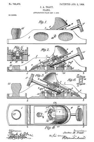
Figure 1 is a side elevation of a plane embodying the improvements of my invention. Fig. 2 is a longitudinal section of the same, the front handle being, however, broken away and the operating parts shown in position with the plane-iron at the front opening or throat. Fig. 3 is a longitudinal section of a plane embodying my improvement with the parts reversed, showing the plane-iron adjusted through the rear throat or opening, Fig. 4 is a plan view of my improved plane, the parts being shown in the position of Fig. 2. Fig. 5 is a cross-sectional view of the plane taken through the pivotal screw-step, the plane-iron and adjusting-screw being removed, showing the step hanging down in the position which it occupies when these parts are removed. Fig. 6 is a cross-sectional view of the adjusting-block through which the adjusting-screw passes and which serves to extend or retract the plane-iron.
1 indicates the body of the plane.
2 is the throat toward the forward end of the plane through which the plane-iron is adapted to project, and 3 is the throat near the rear end of the plane-body.
4 is a plane-iron of suitable construction.
5 is the plane-iron cap for holding the plane-iron securely in place. In the form of my invention herein shown this plane-iron cap terminates at the upper end in a handle portion 6.
7 is a clamping-lever of suitable construction.
8 and 9 are screws which take into the posts 10 and 11, respectively, and for the purpose of coacting with the plane-iron cap for holding it in place.
12 and 13 are oppositely-inclined ways at the rear and front of the plane, respectively, which afford guides for the adjusting-block 14.
15 and 16 are projections from the block 14, adapted to coact with recesses in the rear of the plane-iron 4.
17 is a thumb-nut for operating the adjusting-screw. The threaded portion 18 of the screw coacts with the adjusting-block M.
19 is a step for the adjusting-screw in the form of a yoke which has a screw-threaded portion to correspond with the screw-threads 20 on the adjusting-screw. It will be noted that the pitch of the screw 20 is greater than the pitch of the screw 18. In this instance it is exactly twice, in order that when the thumb-nut 13 is turned in one direction or the other the adjusting-block 14 may move correspondingly as the resultant of the difference between the pitches of the screws.
21 and 22 are pivot-pins for the step 19, which pass through the lugs 23 and 24, which are preferably cast integral with the body of the plane on either side.
25 and Q6 are small grooves cut in the upper surface of the base of the plane to allow slight clearance for the lower end of the adjusting-screw when it is being operated and reversed. Ordinarily the plane is used with the parts in the position as shown in Figs. 1, 2, and 4. When, however, it is desired to use the plane in a corner or some other position, the parts may be reversed, as shown in Fig. 3. To reverse the parts, the cap 5 and the iron 4 are removed after releasing the lever 7, when the adjusting-screw and adjusting block and step may be swung over to the position shown in Fig. 3, the parts pivoting on the axis of the pins 21 and 22. In this position the parts may be again assembled, as shown in Fig. 3, when the plane will operate as before.
The construction will be seen to be simple and not at all likely to become injured or disarranged accidentally, and yet the reversal or adjustment of the parts in either of their positions may be effected without difliculty.
What I claim is —
1. In a plane in combination a body portion, having two throats, a plane-iron, a pivoted step, an adjusting-block, an adjusting-screw coacting with said block and said step and oppositely-inclined guideways forming supports for said adjusting-block.
2. In a plane, a body portion having a plurality of throats, a plane-iron, acap, inclined guideways and cap-screws for said iron toward each of said throats, clamping means and reversible means for manually adjusting the cutting depth of said plane-iron through either of said throats.
3. In a plane, a body portion having two throats, a plane-iron, a cap, cap-screws and a clamp for supporting said iron in position at either throat, and reversible adjusting means coacting with said iron in either position for varying its cutting depth.
4. In a plane, a body having two throats, a plane-iron, a cap, cap-screws, a clamping-lever and a reversible adjusting-block and means for moving said block to adjust the plane-iron through either throat as may be desired.
Signed at New Britain, Connecticut, this 31st day of December, 1903.
JUSTUS A. TRAUT.
Witnesses:
H. S. WALTER,
W. J. WORAM.