| PLEASE NOTE: The images presented on this page are of low resolution and, as a result, will not print out very well. If you wish to have higher resolution files then you may purchase them for only $2.95 per patent by using the "Buy Now" button below. All purchases are via PayPal. These files have all been cleaned up and digitally enhanced and are therefore suitable for printing, publication or framing. Each zip package contains all the images below (some packages may contain more), and purchased files can be downloaded immediately. |
UNITED STATES PATENT OFFICE.
_________________
ALBERT WILLIAM CAMPBELL, OF GLASTONBURY, ENGLAND, ASSIGNOR TO THE STANLEY RULE & LEVEL COMPANY, OF NEW BRITAIN, CONNECTICUT, A CORPORATION OF CONNECTICUT.
PLANE.
_________________
SPECIFICATION forming part of Letters Patent No. 766,491, dated August 2, 1904.
Application filed February 19, 1904. Serial No. 194,429. (No model.)
_________________
To all whom it may concern:
Be it known that I, ALBERT WILLIAM CAMPBELL, a citizen of Great Britain, residing at Glastonbury, in the county of Somerset, England. have invented certain new and useful Improvements in Planes, of which the following is a full, clear, and exact description.
My invention relates to improvenients in planes, and particularly to adjusting mechanism for double-ended planes.
The object of the invention is to provide a simple and inexpensive means for adjusting the plane-iron in a double-ended plane, which adjusting means shall be reversible to cooperate with the plane-iron in either its front or rear position, so as to vary the cutting depth when desired.
The invention consists in providing, first, a plane-body having two openings or throats in the sole portion and supports for the plane-iron for both of these throats; second, a plane-iron and a clamping member with means for holding them in place; third, adjustable and reversible means for projecting or retracting the plane- iron through either one of the throats, as desired.
The details of my invention will be more clearly seen on an inspection of the accompanying single sheet of drawings, in which —
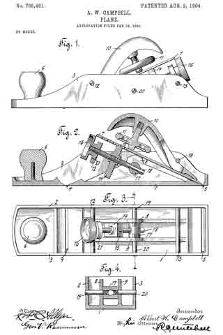
Figure 1 is a side elevation of a plane embodying the improvements of my invention, the plane-iron being projected through the forward throat. Fig. 2 is a central longitudinal section of the plane with the iron projected through the rear throat. Fig. 3 is a plan view of the plane-body and the adjusting mechanism in the position of Fig. 2, the plane-iron and clamp being removed. Fig. 4 is a vertical cross-section taken on the plane of the line 4 4, Fig. 3.
1 indicates the sole portion of the plane. 2 and 3 are the side flanges which reinforce and strengthen the same 4: is the front throat or opening through which the cutting edge of the plane-iron may project.
5 is the rear throat.
6 is a handle which may be conveniently provided at the fore end of the plane.
7 is a plane-iron which at its cutting edge is supported by a portion of the sole.
8 and 9 are supports for the plane-iron 7 intermediate the throats 4; and 5.
10 is a cap member which bears against the plane-iron near the lower end.
11 is a clamping member carried by the cap which coacts with the plane-iron.
12 and 13 are cross-bars supported by the flanges 2 and 3 of the plane. The cap is inserted beneath one of these cross-bars, and the clamp 11 holds the parts in place.
14 is an adjusting-block having a projection 15 at the upper end for coacting with a recess or perforation in the plane.-iron.
16 is an adjusting-screw for coacting with the adjusting-block to move it back and forth, so as to vary the cutting depth of the plane-iron.
17 is a pivoted step for the adjusting-screw.
18 is a washer over which the lower end of the adjusting-screw is riveted to hold the same in place, so as to prevent the adjusting-screw from moving longitudinally with relation to the step 17.
19 and 20 are pivot-screws which extend through the side flanges 2 and 3 and also through the supports 8 and 9 and are screwed into the step 17. The lower end of the adjusting-block is guided between the inner faces of the supports 8 and 9, and thus prevented from rotation with respect to the adjusting-screw. The rotation of the adjusting-screw thus causes longitudinal movement of the plane-iron.
21 is a wheel or roller carried by the adjusting-screw 16, which rests upon the cross-bar 12 when the parts are in the position shown in Fig. 2. This supports the adjusting-screw toward the upper end. Of course when the plane-iron is reversed the cap 10 is inserted under the rod 12 and the wheel 21 rests on the rod 13, the adjusting and clamping means being reversible and interchangeable in this respect.
It will be obvious to one skilled in the art that many changes and alterations might be made in the construction shown in the drawings without departing from the spirit or scope of my invention.
What I claim is —
1. In a double-ended plane, a body portion having two throats, a plane-iron and reversible means for adjusting the cutting depth of the iron at either throat.
2. Adouble-ended plane comprising a body portion having two throats, a plane-iron and a pivoted reversible means for adjusting its cutting depth of said plane-iron through either of said throats.
3. A plane comprising the combination of a body portion with two throats, a step, pivots therefor, a screw coacting with said step and an adjusting-block operated by said screw.
4. In a plane, a body portion having side flanges and two throats in the sole, a plane-iron, clamping means therefor, two rods connecting said flanges, supports between said throats for said iron, a step, an adjusting-screw for said iron coacting with said step and adapted to coact with either one of said rods for support.
5. In a plane, a. body portion having two throats, supports between said throats, a plane-iron, a reversible adjusting-block therefor, a guide for said block to the rear of each throat to prevent its rotation and a screw coacting with said block for the purpose specified.
6. In a plane, a body having two throats, two supports therein, a plane-iron, a step pivotally mounted between said supports, an adjusting-block, and a screw coacting with said step and said block.
Signed at Shepton Mallet, in the county of Somerset, England, this 4th day of February, 1904.
ALBERT WILLIAM CAMPBELL.
Witnesses:
P. MAGGS,
T. E. RUSSELL.


