
| PLEASE NOTE: The images presented on this page are of low resolution and, as a result, will not print out very well. If you wish to have higher resolution files then you may purchase them for only $2.95 per patent by using the "Buy Now" button below. All purchases are via PayPal. These files have all been cleaned up and digitally enhanced and are therefore suitable for printing, publication or framing. Each zip package contains all the images below (some packages may contain more), and purchased files can be downloaded immediately. |
UNITED STATES PATENT OFFICE.
_________________
EDMUND A. SCHADE, OF NEW BRITAIN, CONNECTICUT, ASSIGNOR TO STANLEY RULE & LEVEL COMPANY, OF NEW BRITAIN, CONNECTICUT, A CORPORATION OF CONNECTICUT.
PLANE.
_________________
SPECIFICATION forming part of Letters Patent No. 769,408, dated September 6, 1904.
Application filed June 4, 1904. Serial No. 211,073. (No model.)
_________________
To all whom it may concern:
Be it known that I, EDMUND A. SCHADE, a citizen of the United States, residing at New Britain. in the county of Hartford, State of Connecticut, have invented certain new and useful lmprovements in Planes, of which the following is a full, clear, and exact description.
My invention relates to improvements in planes.
The object of my invention is to provide means for adjustment of the plane-iron and means for locking the same to prevent accidental movement.
The invention consists in improvements the principles of which are illustrated in the accompanying single sheet of drawings.
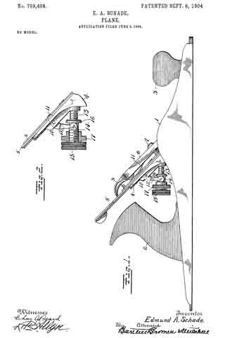
Figure 1 is a side elevation of a plane embodying the improvements of my invention. Fig. 2 is a detail fragmentary view showing the parts particularly necessary for comprehension out my improvement, a portion of the figure being shown in section.
1 indicates the body of a plane of any suitable construction. This in the form shown has handles 2 and 3. 4 is a frog of any suitable construction which provides a bearing for the plane-iron 5. 6 is a plate winch serves to reinforce the plane-iron and in this particular instance affords the means of connection for the adjusting mechanism. 7 is a cap-screw which takes into the frog in any well-known manner. 8 is a cap coacting therewith, and 9 is a clamp for holding the parts in their proper position. All of these parts thus far described may be of any suitable construction.
The cutting depth or position of the plane-iron may be varied by means of a lever, which is commonly termed a “Y adjustment.”
In the drawings, 10 indicates a pivot-pin carried by the frog and upon which the adjustment-lever is mounted.
11 is the nose of the lever, and 12 is one of the depending arms.
13 is a screw-post which is securely fastened to the frog 4.
14 is an operating-sleeve mounted to operate on the post 13 and having, preferably, a milled head 15.
16 is a shoulder or flange carried by the inner end and adapted to coact with the arm 12 of the adjusting-lever.
17 is a member which is carried by the sleeve 14. This aliords a bearing for one side of the arm 12 of the Y adjustment, so that when the sleeve 14 is moved longitudinally on the post 13 the arm 12 is rocked to and fro to move the cutting-iron.
The adjusting-sleeve 14; as commonly constructed is likely to accidentally turn and move on the post 13 as the plane is used. This results sometimes in derangement of the adjustment of the plane and at all times tends to wear the parts unduly. By my construction this is avoided. The member 17 is preferably milled on the edge and may be adjusted on the post 14 to securely engage the arm 12 and clamp the same in position against the flange 16. The friction of the parts against the arm 12 serves to prevent the adjusting-sleeve from rotating on the post 13. As a consequence the adjusting-lever cannot move and the sleeve has no free play to cause wear on the parts. The plane-iron may be adjusted by releasing the clamping mernber 17 and then operating the adjusting-sleeve. The advantages of this construction will be apparent to those skilled in this art.
What l claim is —
1. In a plane, the combination of a body portion, a frog, a plane-iron and adjusting member, a post, a sleeve adjustable on said post and coacting with said member and a clamping member mounted on said sleeve and also coacting with said member for the purpose specified.
2. In a plane, the combination of a body portion, a frog, a plane-iron, an adjusting member coasting therewith, a screw-threaded post, an adjusting-sleeve screw-threaded on said post, a clamping-sleeve screw-threaded on said adjusting-sleeve and rotatable therewith and also independently thereof said sleeve and clamping member coacting with said adjusting member for the purpose specified.
Signed at New Britain, Connecticut. this 1st day of June, 1904.
EDMUND A. SCHADE.
Witnesses:
H. S. WALTER,
W. J. WORAM.