
| PLEASE NOTE: The images presented on this page are of low resolution and, as a result, will not print out very well. If you wish to have higher resolution files then you may purchase them for only $2.95 per patent by using the "Buy Now" button below. All purchases are via PayPal. These files have all been cleaned up and digitally enhanced and are therefore suitable for printing, publication or framing. Each zip package contains all the images below (some packages may contain more), and purchased files can be downloaded immediately. |
UNITED STATES PATENT OFFICE.
_________________
CHARLES C. CROSSLEY, OF NEW BRITAIN, CONNECTICUT.
MOLDING OR BEADING PLANE.
_________________
SPECIFICATION forming part of Letters Patent No. 771,463, dated October 4, 1904.
Application filed February 13, 1904. Serial No. 193,362. (No model.)
_________________
To all whom it may concern:
Be it known that I, CHARLES C. CROSSLEY, of New Britain, in the county of Hartford and State of Connecticut, have invented a new and useful Improvement in Molding or Beading Planes; and I do hereby declare the following, when taken in connection with the accompanying drawings and the letters of reference marked thereon, to be a full, clear, and exact description of the same, and which said drawings constitute part of this specification, and represent, in —
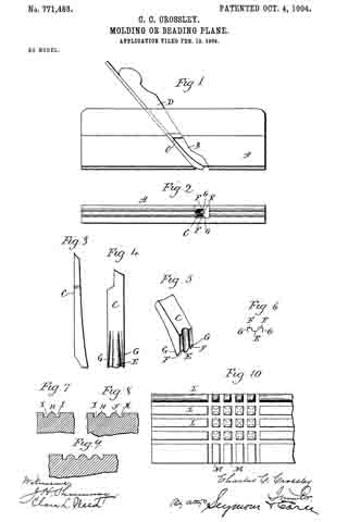
Figure 1, a side view of a plane containing a cutter constructed in accordance with my invention; Fig. 2, a bottom view thereof; Fig. 3, a side view of the lower end of the cutter detached; Fig. 4, a front view of the same; Fig. 5, a perspective view of the cutter looking at the rear; Fig. 6, an outline of the cutting edge; Fig. 7, a sectional view of a block showing a single cut; Fig. 8, a similar view with two cuts; Fig. 9, a similar view with three cuts; Fig. 10, a plan view of a block showing cuts made at right angles.
This invention relates to an improvement in molding or beading planes, and particularly to the cutters therefor, the object of the invention being to so form the cutter that it may be used in stocks of ordinary construction and by which beads may be cut in every direction and, if desired, at angles to each other; and the invention consists in the construction as hereinafter described, and particularly recited in the claim.
In carrying out my invention I employ a stock A, which may be a center-bead stock, as shown, or a side-bead stock, having the usual mortise B for the reception of a cutter C, which is held in place by the usual wedge D. The operating edge of the cutter has a central half-round portion E, horizontal lower cutters F, and upwardly-extending side cutters or lips G, the end of the cutter being so formed that the cutting edges of the lower critters F are in rear of the cutting edge of the center portion E, whereby a drawing cut is made which assists in cutting smoothly and in any direction as regards the grain of the wood.
The plane is operated in the usual manner and if used upon the surface of wood the first cut will form a half-round bead H, with grooves I on opposite sides thereof, the outer walls of the grooves being straight, as shown in Fig. 7. If two beads are desired, the plane is moved to one side, so that one of the cutters F and the lip G ride in the groove formed at one side of the half-round bead H, which forms a guide for the plane and allows the central portion of the cutter to form a second half-round bead J and a groove K at one side, having a straight side wall, as shown in Fig. 8, or three beads may be formed, as shown in Fig. 9, and this can be continued indefinitely. In Fig. 10 of the drawings I have shown beads L and M crossing each other at right angles, and, as before stated, with my improved cutters these beads may be formed in any direction.
Having fully described my invention, what I claim as new, and desire to secure by Letters Patent, is —
In a plane, the combination with the stock, of a cutter having a central rounded cutting edge, straight cutters on opposite sides of the center and in rear thereof, and side cutters or wings extending upward and forward therefrom, substantially as described.
In testimony whereof I have signed this specilication in the presence of two subscribing witnesses.
CHARLES C. CROSSLEY.
Witnesses:
AARON DANIELSON,
CHAS. A. ERICSON.