| PLEASE NOTE: The images presented on this page are of low resolution and, as a result, will not print out very well. If you wish to have higher resolution files then you may purchase them for only $2.95 per patent by using the "Buy Now" button below. All purchases are via PayPal. These files have all been cleaned up and digitally enhanced and are therefore suitable for printing, publication or framing. Each zip package contains all the images below (some packages may contain more), and purchased files can be downloaded immediately. |
UNITED STATES PATENT OFFICE.
_________________
JOHN MUEHL, OF CLEVELAND, OHIO.
PLANE.
_________________
SPECIFICATION forming part of Letters Patent No. 775,378, dated November 22, 1904.
Application filed May 27, 1903. Serial No. 158,939. (No model.)
_________________
To all whom it may concern:
Be it known that I, JOHN MUEHL, a citizen of the United States of America, residing at Cleveland, in the county of Cuyahoga and State of Ohio, have invented certain new and useful Improvements in Planes; and I hereby declare the following to be a full, clear, and exact description of the invention, such as will enable others skilled in the art to which it pertains to make and use the same.
This invention relates to a new and useful improvement in bench-planes.
The object of this invention is to provide a device of this character which can be used on any kind of wood and will not clog or tear the wood.
A further object of my invention is to reduce the cost of manufacture and simplify the construction of bench-planes by providing a simple arrangement of bit-adjusting mechanism by means of which the bit can be easily and accurately adjusted longitudinally to regulate the depth of the cut and laterally to line up the edge of the bit with the sole or face of the plane.
My invention therefore consists in providing a plane having a plate secured in the stock thereof which serves both as a cap and as a clamping-plate and which also forms the sole support for all the adjusting mechanism.
My invention further consists in providing an arrangement of bit-adjusting mechanism by means of which the bit can be set by operating a single lever, by the rotation of which the longitudinal adjustment of the bit can be secured, and by the oscillatory movement of which the edge of the bit can be alined with the sole or face of the plane.
My invention further consists in the features of construction and combination of parts hereinafter described in the specification, pointed out in the claims, and illustrated in the drawings.
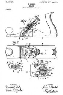
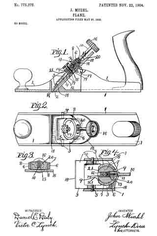
In the accompanying drawings, Figure 1 is a side elevation, partly in section, of my improved plane. Fig. 2 is a top plan. Fig. 3 is a section on line 3 3, Fig. 1. Fig. at is a section on line 4 4, Fig. 1.
Again referring to the drawings, 1 represents the stock of the plane, which is provided with the bit-opening or throat 2. A combined cap or clamping plate 3 is secured in the cheek-plates of the stock by means of pins 4 and 5. The lower edge of the plate 3 is provided with a knife-edge which is arranged flush with the sole or face of the plane.
Near the top of the plate 3 is formed a boss 6, in which is formed a screw-threaded opening 7. In the side of the boss and communicating with the opening 7 is formed a slot 20, and the opposite side of the boss is cut away, as at 21. In the screw-threaded opening 7 is arranged a screw-threaded plug 8, in which is formed an opening 9, the axis of which is at a right angle to the axis of the opening 7, and said opening is screw-threaded the greater part of its length. An adjusting-arm 10 is screw-threaded at one end and is arranged to screw into the screw-threaded opening 9 in the plug 8. The plug 8 therefore forms the fulcrum for the single adjusting-arm 10. In the end of the arm 10 is formed a screw-threaded bore 11. A small block 12 is provided with a screw-threaded stem 13, arranged to screw into the bore 11 in the end of the adjusting-arm 10. The exterior screw-thread on the lever 10 and the screw-thread in the plug 8 are preferably right-hand screw-threads, and the internal screw-threads in the end of the lever 10 and the screw-thread on the stem 13 are preferably left-hand screw-threads. In the block 12 is mounted a set-screw 14, which is provided with a reduced end portion 15. The arm 10 is preferably provided with a knob 16. A support 17 is rigidly secured between the cheek-plates of the stock, and between this support 17 and the plate 3 is arranged a bit 18. In this bit are formed a series of holes 19, arranged to receive the end of the set-screw 14, so as to secure the bit to the plate 3 and clamp it against the support 17.
The construction and operation of my plane is so simple that it can be readily understood.
When the knob of the arm is turned to the right, the end of the arm will be screwed down into the plug, thereby advancing the block and causing the bit which is secured thereto to project through the throat of the plane. By turning the knob of the arm to the left the arm will be screwed out of the plug, drawing the block into the plug and retracting the bit in the throat of the plane. Again, by swinging the arm to the left or to the right on the plug as a fulcrurn the opposite edges of the bit can be caused to project through or be retracted in the throat of the plane, thereby securing perfect alinement of the edge of the bit with the sole or face of the plane.
I have described and illustrated my preferred construction; but it will be readily seen that the same can be changed without departing from the spirit of my invention. For instance, most of the screw-threads are provided only for the purpose of allowing the members to rotate in their respective mountings, and any method of mounting which will permit a rotary movement of the members can be substituted and all screw-threads omitted except one on the arm 10 and a corresponding screw-thread either in the plug 8 or on the block 12 and any other means substituted which will allow a free rotary movement and supply a connecting or binding means at the same time.
What I claim is —
1. A plane comprising a stock, a stationary plate, an arm fulcrumed on said plate, and arranged to have both an oscillatory and a rotary movment, a bit, means for causing the arm to travel longitudinally when rotated, and means forming an operative connection between said arm and said bit so that the rotary movement of said arm will cause a longitudinal movement of said bit and the oscillatory movement of said arm will cause a lateral shifting of said bit so as to aline the cutting edge of said bit with the face of the plane.
2. A plane comprising a stock, a stationary plate, a fulcrum rotatably mounted on said plate, an arm rotatably mounted in said fulcrum, a bit, means for causing the arm to travel longitudinally when rotated, and means for forming an operative connection between said bit and said arm so that the rotary movement of said arm will cause a longitudinal movement of said bit and the oscillatory movement of said arm will cause a lateral shifting of said bit, for the purpose set forth.
3. A plane comprising a stock, a stationary plate, a fulcrum rotatably mounted on said plate and provided with a screw-threaded opening, an arm arranged to screw into said screw-threaded opening, a block, means for securing said block to the end of said arm so as to allow the arm to rotate without rotating said block, a bit, and means for securing said block to said bit.
4. A plane comprising a stock, a stationary plate, a fulcrum rotatably mounted on said plate and provided with a screw-threaded opening, an arm adapted to screw into said fulcrum, a block, means for securing said block to the end of said arm so as to allow the arm to rotate without rotating said block, a bit, and a set-screw for securing said bit to said block.
5. A plane comprising a stock, a stationary plate, a fulcrum rotatably mounted on said plate, an arm arranged to screw into said fulcrum, a block arranged to screw on the end of said arm, a bit and means for securing said block to said bit.
6. A plane comprising a stock, a stationary plate, a fulcrum rotatably mounted on said plate, an arm arranged to screw into said fulcrum and havinga screw-threaded bore in its lower end, a block, a screw-threaded stem formed on said block and arranged to screw into the end of said arm, a bit and means for securing said bit to said block.
7. A plane comprising a stock, a stationary plate, a fulcrum rotatably mounted on said plate, an arm arranged to screw into said fulcrum, a block secured on the end of said arm so as to allow the arm to rotate without rotating the said block, a support, a bit arranged between said plate and said support and a set-screw mounted in said block and arranged to secure the said block to the said bit and clamp said bit between said plate and said support.
8. A plane comprising a stock, a stationary plate, a fulcrum rotatably mounted on said plate, an arm arranged to screw into said fulcrum and having a screw-threaded bore, a block provided with a screw-threaded stem arranged to screw into the bore in said arm, a support, a bit arranged between said plate and said support and a set-screw mounted in said block and arranged to secure said block to said bit and clamp said bit between said plate and said support.
9. A plane comprising a stock, a stationary plate, an arm having a screw-threaded end rotatably secured on said plate, a block provided with a screw-thread arranged to engage the screw-thread on said arm, a bit, and means for securing said bit to said block.
10. A plane comprising a stock, a stationary plate, a fulcrum rotatably mounted on said plate, an arm rotatably secured in said fulcrum and having a screw-threaded bore formed in the end thereof, a block, a screw-thread formed on said block and arranged to screw into the bore of said arm, a bit and means for securing said block to said bit.
11. A plane comprising a stock, a stationary plate, a fulcrum mounted on said plate, an arm rotatably secured in said fulcrum and provided with a screw-threaded end, a block provided with a screw-thread arranged to engage the screw-thread on said arm, a bit and means for securing said bit to said block.
12. A plane comprising a stock, astationary plate, an arm having a screw-threaded bore formed in the end thereof, means for rotatably securing said arm on said plate, a block, a screw-threaded stem formed on said block and arranged to screw into the bore in said arm, a bit and means for securing said block to said bit.
13. A plane comprising a stock, a stationary plate. a fulcrum rotatably mounted on said plate, an arm, means for securing said arm on said fulcrum to oscillate and also to rotate therein. a bit and means for securing said bit to said arm, the arrangement being such that the rotary movement of said arm will cause a longituclinal movement of said bit, and the oscillatory movement of said arm will cause a lateral shifting of said bit for the purpose set forth.
In testimony whereof I sign the foregoing specification, in the presence of two witnesses, this 9th day of May, 1903, at Cleveland, Ohio.
JOHN MUEHL.
Witnesses:
VICTOR G. LYNCH,
G. M. HAYES.

