| PLEASE NOTE: The images presented on this page are of low resolution and, as a result, will not print out very well. If you wish to have higher resolution files then you may purchase them for only $2.95 per patent by using the "Buy Now" button below. All purchases are via PayPal. These files have all been cleaned up and digitally enhanced and are therefore suitable for printing, publication or framing. Each zip package contains all the images below (some packages may contain more), and purchased files can be downloaded immediately. |
UNITED STATES PATENT OFFICE.
_________________
ARTHUR J. REYNOLDS, OF NEW BRITAIN, CONNECTICUT, ASSIGNOR TO THE STANLEY RULE & LEVEL COMPANY, OF NEW BRITAIN, CONNECTICUT, A CORPORATION OF CONNECTICUT.
PLANE.
_________________
SPECIFICATION forming part of Letters Patent No. 780,064, dated January 17, 1905.
Application filed June 10, 1904. Serial No. 211,580.
_________________
To all whom it may concern:
Be it known that I, ARTHUR J. REYNOLDS, a citizen of the United States, residing at New Britain, in the county of Hartford, State of Connecticut, have invented certain new and useful Improvements in Planes, of which the following is a full, clear, and exact description.
My invention relates to improvements in planes, and particularly to an adjusting-lever for the plane-iron.
The object of my invention is to simplify the construction of the same, lessen the cost of manufacture, and increase the general efficiency and ease of operation.
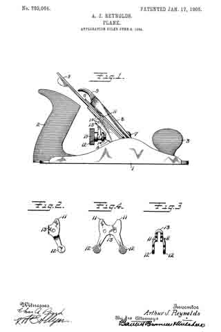
Figure 1 is a side elevation of a plane embodying the improvements of my invention. Fig. 2 is a side view, on an enlarged scale, of what may be termed the “adjusting-lever.” Fig. 3 is a top view of the same. Fig. 4 is a plan of a blank of sheet of wrought metal from which the adjusting-lever is formed.
1 indicates the body of the plane of suitable construction. The form herein is shown with a rear handle 2 and a front handle 3.
4 is a frog secured to the body portion by any suitable means.
5 is a cutting-iron of usual construction.
6 is a plate which may be used to reinforce the plane-iron and also afford a convenient means for cooperating with the adjusting mechanism.
7 is a cap-screw secured to the frog.
8 is a cap and 9 a clamping member.
All of the parts thus far described may be of any suitable construction.
The form of my invention which I have illustrated employs what is known as the “Y adjusting-lever” for varying the cutting depth of the plane-iron. This member is pivoted on pin 10, ordinarily carried by the frog 4. The adjusting-lever is formed of wrought or sheet metal blanked out in the form shown in Fig. 4 and afterward shaped up into the form shown in Figs. 1, 2, and 3. 11 indicates one of the ends of the duplex nose, which fits into a suitable recess in the plate 6, as is common. 12 indicates one end or arm of the adjusting-lever. 13 is the connecting portion in the form of a U bend between the two side arms and the duplex nose. This construction affords a broad bearing upon the pin 10 with the use of a small amount of metal, which is consequently economical and light in weight. The distance between the ends of the duplex nose affords a broad bearing for engagement with the plane-iron or plate.
14 is a post carried by the frog 4, and 15 is a sleeve which operates on the post 14 for cooperating with the arms 12 12 of the adjusting-lever. By means of this sleeve 15 the position of said lever may be varied to vary the depth of the cutting-iron as desired.
The forming of the adjusting-lever as shown affords great strength, since the U bend increases the strength at this point materially. The fiber of the metal is also so disposed at the point of contact with the plane-iron as to give a minimum amount of friction. The advantages of such a construction will be apparent to those skilled in the art.
What I claim is —
A plane-iron adjusting lever shaped to form arms at the respective ends for engaging the adjusting and the adjusted parts and an enlarged intermediate fulcrum portion comprising two side members united by a bend.
Signed at New Britain, Connecticut, this 6th day of June, 1904.
ARTHUR J. REYNOLDS.
Witnesses:
H. S. WALTER,
W. J. WORAM.


