
| PLEASE NOTE: The images presented on this page are of low resolution and, as a result, will not print out very well. If you wish to have higher resolution files then you may purchase them for only $2.95 per patent by using the "Buy Now" button below. All purchases are via PayPal. These files have all been cleaned up and digitally enhanced and are therefore suitable for printing, publication or framing. Each zip package contains all the images below (some packages may contain more), and purchased files can be downloaded immediately. |
UNITED STATES PATENT OFFICE.
_________________
EDMUND A. SCHADE AND ALBERT F. SCHADE, OF NEW BRITAIN, CONNECTICUT, ASSIGNORS TO
STANLEY RULE & LEVEL COMPANY, OF NEW BRITAIN, CONNECTICUT, A CORPORATION OF CONNECTICUT.
PLANE.
_________________
SPECIFICATION forming part of Letters Patent No. 787,054, dated April 11, 1905.
Application filed October 22, 1904. Serial No. 229,520.
_________________
To all whom it may concern:
Be it known that we, EDMUND A. SCHADE and ALBERT F. SCHADE, citizens of the United States, residing at New Britain, Hartford county, Connecticut, have invented certain new and useful Improvements in Planes, of which the following is a full, clear, and exact description.
Our lnvention relates to improvements in planes.
The object of the invention is to provide a plane with an adjustable tilting handle, so that it may be grasped by the hand and operated in many positions and cases where at present a plane cannot be used except with great danger of accident to the knuckles and the back of the hand, which are liable to be bruised.
The invention is illustrated in the accompanying single sheet of drawings.
The body of the plane carries a bearing for the handle, so that the handle can be tilted to either side and secured in place or used in a vertical position, as is customary.
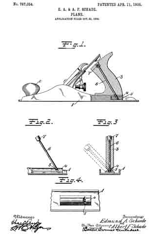
Figure 1 is a side elevation of a plane, showing those parts which embody the improvements of our invention in vertical section. Fig. 2 is a fragmentary detail showing the parts for securing the handle in position. Fig. 3 is a vertical cross-section showing the method of attachment. Fig. 4 is a plan view of a fragment of the body of a plane, showing the bearing for the handle.
1 indicates the body of a plane, which may be of any suitable character and constructed of any suitable material. The frame herein shown is made of cast-iron.
2 is a knob which may conveniently be provided at the front end of the plane, as is common.
3 is a handle of suitable conformation and material.
4 is a bearing for the handle, which extends lengthwise of the body for some distance. This is shown integral with the body; but it is obvious that it may be made separate and bolted or riveted or otherwise secured in place.
5 is a pin or roller which is mounted in the bearing-block 4 and adapted to rotate or oscillate from side to side through a limited extent.
6 is a rod which is screw-threaded at the lower end and takes into the pin 5.
7 is a screw-cap cooperating with the upper end of the rod 6 for securely clamping the parts together.
The parts are preferably assembled by first attaching the rod 6 to the pin 5, then slipping the handle member 3 over the rod 6, and lastly fixing the cap 7 in place. By tightening the cap the handle may be securely held in place on its seat on the bearing-block 4 in any position, as indicated, for instance, in dotted lines in Fig. 3, While this construction is exceedingly simple, it does provide a means for avoiding such accidents as in the past have been quite common when using an ordinary plane in certain positions — such as, for instance, planing deep rabbets or when operating upon jack-boards. The handle, moreover, may be secured in place in the ordinary upright position for usual work.
It is obvious that many changes may be made in the details of construction without departing from the spirit or scope of our invention.
What we claim is —
1. In a plane, the combination of a body or stock portion having a long semicylindrical bearing, a handle member having a corresponding semicylindrical bearing, a pin mounted to oscillate in the body portion and a rod passing through said handle member and secured to said pin with means to coact therewith for clamping the handle in position at different angular positions.
2. In a plane, the combination of a body or stock portion having a longitudinal bearing, a handle tiltingly seated thereon, a pin mounted in said body portion and a rod passing through said handle and screwed into said pin with means for coasting therewith and clamping said handle in position.
3. In a plane the combination of a body portion having a bearing, a handle mounted to tilt thereon, a pin rotatably mounted in said stock portion beneath said bearing, a rod passing through said handle and screw-seated in said pin and a cap coacting with said rod and said handle and accessible for clamping said handle in position.
Signed at New Britain, Connecticut, this 20th day of October, 1904.
EDMUND A. SCHADE.
ALBERT F. SCHADE.
Witnesses:
W. J. WORAM,
E. G. HOFFMAN.