
| PLEASE NOTE: The images presented on this page are of low resolution and, as a result, will not print out very well. If you wish to have higher resolution files then you may purchase them for only $2.95 per patent by using the "Buy Now" button below. All purchases are via PayPal. These files have all been cleaned up and digitally enhanced and are therefore suitable for printing, publication or framing. Each zip package contains all the images below (some packages may contain more), and purchased files can be downloaded immediately. |
UNITED STATES PATENT OFFICE.
_________________
ALEXANDER KALLA, OF NEW YORK, N. Y.
CARPENTER’S PLANE.
_________________
SPECIFICATION forming part of Letters Patent No. 787,624, dated April 18, 1905.
Application filed December 10, 1904. Serial No. 236,272.
_________________
To all whom it may concern:
Be it known that I, ALEXANDER KALLA, a resident of the city of New York, borough of Manhattan, county and State of New York, have invented certain new and useful Improvements in Carpenters’ Planes, of which the following is a specification.
This invention relates to an improved carpenter’s plane, in which the main object is to incorporate two planes in one. In other words, when the two are together a jack-plane is formed, and by taking them apart the smaller one can be used alone.
To these and other ends which will hereinafter appear the invention consists in the novel features of improvement and combination and arrangement of parts, which will be hereinafter described, and finally summarized in the appended claim.
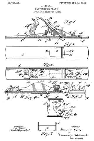
Reference is to be had to the accompanying drawings, forming part of this specification, wherein —
Figure 1 is a side elevation, partly in section, of a plane embodying my improvements. Fig. 2 is a top plan view with the cutting-tool and accessories removed. Fig. 3 is a bottom plan view. Fig. 4 is a section of the stock of the small plane, the section being taken on the line a a in Fig. 2. Fig. 5 is an end view thereof. Fig. 6 is a detail view of the swivel-lock; and Fig. 7 is a transverse section of the shoe 1, taken on the line B B in Fig. 1 looking in the direction of the arrow.
Like numerals or letters of reference indicate corresponding parts in the several views.
Referring to the accompanying drawings, the numeral 1 indicates the large shoe of my plane, having detachably mounted thereon a stock 2, the stock 2 being held in place by a dog 3 and a swivel-clip 4.
Upon the end of the stock 2 adjacent to the clip 4 is a swivel-lock 5, (see Fig. 6,) which is mounted upon a stud 6, fastened to the stock 2. A knob 7 is mounted upon the stud 6 in the manner shown and is free to be screwed down upon the swivel to secure the same.
Upon the bottom of stock 2 is a projecting portion 8, adapted to fit the opening 9 in shoe 1. Through said projection a cutting-tool 11 passes, said tool being braced by the member 12, which is provided with a lock 13, all of which are carried by the bracket 14, said bracket being held by the stock 2, this being a well-known construction of cutting means usually employed in carpenters’ planes. The projection 8 serves as an abutment when parts 1 and 2 are interlocked and also prevents the tool 11 from chattering.
Upon the bottom of stock 2 an adjustable gib 15 is fitted, (see Fig. 4,) there being two such gibs, one being held by pins 16 16a and the other by pins 17a 17b, at opposite ends thereof, the pin 17a passing through a slot or recess 18 in the swivel-lock 5 and a suitable opening in the bottom of stock 2, the pin 16 also passing through the bottom of stock 2 and extending somewhat above the bottom portion of said stock. Adjacent to th pins 16 16a are slide-locks 19 20, which are held in place by pins 21 21 and are provided with operating-pins 22.
The swivel-lock 5 is provided with an operating-pin 23, which projects below the same and into a slot 24, which slot limits the movement of said clip or lock.
Fig. 7 shows the corners of the body 1, which lie between the lines C C, Fig. 1, as rounded, the corners D D of stock 2, Fig. 5, fitting the same, whereby agood tight sliding fit is provided.
It will be seen from Fig. 2 that the stock 2 has upon its rear end a rounded projection 24a, which is adapted to catch into the dog 3, as shown.
When the body portions 1 and 2 are interlocked, as in Fig. 1, a jack-plane is formed, being held by the projection 24a catching in the dog 3 and the swivel-clip 4 being brought to a position parallel with a median line drawn through the plane and over the lock 5, the cutting-tool passing through the opening 25 in the projection 8. When the parts 1 and 2 are fitted together for use as a jack-plane, the gib 15 will be in a raised position, as shown in Fig. 4, permitting the projection 8 to pass through the opening 9 of body 1, Fig. 1. When the shoe 1 is removed, the gib 15 can be caused to drop (see dotted lines, Fig. 4,) and held down by sliding the locks 19 20 over the pins 16 16a, (as per dotted lines, Fig. 2,) which will fall with the gib and fit the recesses 26 in stock 2, the forward pins 17a 17b also dropping. The swivel-lock 5 can new be swung over the pins 17a 17b (see dotted lines, Fig. 6) and the knob 7 screwed down, thus locking the lock 5. This accomplished, the stock 2 can be employed separately for use as a short plane. The stock 2 is provided with the usual handle 26a. The knob 7 is provided with a screw 27, which is tapped into the stud 6, so that when the knob is turned it travels downwardly upon the lock 5, the screw 27 being held in the knob in suitable manner.
Having now described my invention, what I claim, and desire to secure by Letters Patent, is —
A combination carpenter’s plane, comprising a shoe, said shoe having in the bottom thereof an opening, a plane-stock having a projection adapted to fit in said opening, said projection being thicker than the bottom of said shoe, and an adjustable gib, carried by said plane-stock, said gib being equal in thickness to the difference between the depth of said projection on said plane-stock and the thickness of the bottom of said shoe, and means adapted to position and lock said plane-stock, and gib thereon, firmly to said shoe and to bring the bottom of said plane-stock substantially in line with the bottom of said shoe.
ALEXANDER KALLA.
Witnesses:
HASKEL CORENTHAL,
DAN HERSHFIELD.