
| PLEASE NOTE: The images presented on this page are of low resolution and, as a result, will not print out very well. If you wish to have higher resolution files then you may purchase them for only $2.95 per patent by using the "Buy Now" button below. All purchases are via PayPal. These files have all been cleaned up and digitally enhanced and are therefore suitable for printing, publication or framing. Each zip package contains all the images below (some packages may contain more), and purchased files can be downloaded immediately. |
UNITED STATES PATENT OFFICE.
_________________
FRED ALLEN SHONTZ, OF EUREKA, UTAH.
ADJUSTABLE PLANE-HANDLE.
_________________
SPECIFICATION forming part of Letters Patent No. 790,533, dated May 23, 1905.
Application filed July 27, 1904. Serial No. 218,420.
_________________
To all whom it may concern:
Be it known that I, FRED ALLEN SHONTZ, a citizen of the United States, residing at Eureka, in the county of Juab and State of Utah, have invented a new and useful Improvement in Adjustable Plane-Handles, of which the following is a specification.
This invention is an adjustable handle for planes, and while capable of use in connection with any construction of plane is preferably employed in connection with the rabbet-plane having a metal base.
The object of the invention is to provide a plane having a laterally-adjustable handle, so that the said plane can be conveniently used in positions where it would be inconvenient to use a plane with a non-adjustable handle, owing to the hand of the operator coming in contact with the work being operated upon.
The invention consists in the novel features of construction and combination of parts hereinafter fully described, and pointed out in the claims.
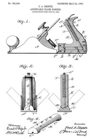
In the drawings forming a part of this specification, Figure 1 is a sectional elevation illustrating my invention. Fig. 2 is an end view of the plane provided with my improved form of handle, the dotted lines showing the different adjustments of the handle. Fig. 3 is a sectional view taken through the handle. Fig. 4 is a detail perspective view of the block to which the handle is connected.
In carrying out my invention I employ a plane A, the base A’ of which is provided with an essentially rectangular-shaped boss B, to which is secured a block C, essentially semi-circular in cross-section, the bottom face of said block being cut away intermediate the ends, as shown at C’, in order to fit snugly upon the boss B. Screws D and D’ are employed for securely connecting the block C to the boss B on the base of the plane. E indicates the handle, which is shaped substantially the same as the ordinary handle, said handle being connected to the block C by means of brackets F and G, having journal or pivot portions F’ and G’, which engage the bearing-recesses C2, formed in the lower face of the end portions of the block C. The handle E has a bore H extending from the upper to the lower end thereof, the upper portion of said bore being of greater diameter than the lower portion, and working in said bore is the locking-rod I, having a pin K passed transversely therethrough, and bearing upon said pin is a spiral spring L, the normal tendency of which is to project the lower end of the rod through the handle and into engagement with one of a series of oblique openings M, formed radially in the periphery of the block C, thereby locking the handle in either a central or a right or left position. The upper end of the spring L engages the tubular plug N, fitted in the upper end of the bore H, and a thumb-lever O is pivoted at O’ to the top of the handle E and is pivotally connected at O2 to the upper end of the rod I, and by pressing downwardly upon said thumb-lever the said rod is drawn up into the handle, so as to disengage its lower end from the opening M, and the handle can then be adjusted to the desired position and the rod will be thrown into engagement with the block by means of the spring L. It will thus be seen that I provide an adjustable handle and means for connecting the same to the base or stock of the plane, and it will be noted that said handle and its attaching means are capable of use in connection with any of the ordinary construction of planes now in use.
Having thus fully described my invention, what I claim as new, and desire to secure by Letters Patent, is —
1. A plane having a block secured to its base, a handle having brackets connected to the opposite ends thereof, said brackets being pivotally connected to the ends of the block, said block having a series of openings arranged at different angles, a spring-actuated locking-rod arranged in the handle and adapted to engage the said openings and means for raising said locking-rod as set forth.
2. A plane, the base of which is provided with a boss, a block semicircular in cross-section, recessed upon its lower face, and secured to the boss, the opposite ends of said block having bearing-recesses, a handle having a bore extending therethrough, a spring-actuated rod arranged in said bore and provided with a thumb-lever for raising the said rod, block having a series of openings arranged upon different angles and adapted to be engaged by the lower end of the looking-rod, and brackets attached to the ends of the handle and provided with journals adapted to engage the bearing-recesses in the ends of the block as set forth.
FRED ALLEN SHONTZ.
Witnesses:
D. B. CRONIN,
F. CHRISTIANSON.