
| PLEASE NOTE: The images presented on this page are of low resolution and, as a result, will not print out very well. If you wish to have higher resolution files then you may purchase them for only $2.95 per patent by using the "Buy Now" button below. All purchases are via PayPal. These files have all been cleaned up and digitally enhanced and are therefore suitable for printing, publication or framing. Each zip package contains all the images below (some packages may contain more), and purchased files can be downloaded immediately. |
UNITED STATES PATENT OFFICE.
_________________
FREDERICK HESLEY, OF WATERTOWN, NEW YORK.
ROUTER.
_________________
SPECIFICATION forming part of Letters Patent No. 793,297, dated June 27, 1905.
Application filed March 1, 1905. Serial No. 247,881.
_________________
To all whom it may concern:
Be it known that I, FREDERICK HESLEY, a citizen of the United States, residing at Watertown, in the county of Jefferson and State of New York, have invented certain new and useful irnprovernents in Routers, of which the following is a specification.
This invention relates to improvements in routers designed for use by carpenters and pattern and cabinet makers for cutting channels or grooves in woodwork, &c.
The object of the invention is to provide a router which is simple in construction, strong, and composed of but a few parts and in which provision is made for interchangeably applying cutting-tools of different size and shape and in which the cutting-tool is provided with “dadoes” or cutting-spurs for the purpose of rendering the work ot channeling and grooving more effective and rapid.
The invention further consists of novel and simple means for adjusting the cutting parts.
The invention further consists in a router comprising the construction and arrangement of of parts hereinafter set forth in the drawings and detailed specification and particularly pointed out in the claims.
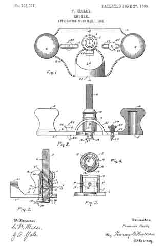
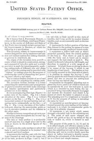
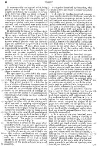
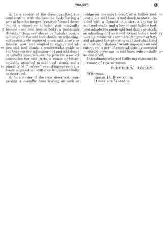
In the accompanying drawings, Figure 1 is a plan view of the router. Fig. 2 is a front elevation of the same. Fig. 3 is a vertical section on the line a a of Fig. 1. Fig. 4 is a horizontal section ot the tool holding and adjusting parts, substantially on the line x x of Fig. 23. Fig. 5 is an elevation ot the hollow tool-post, showing the semicircular guide or key in operative position and its relation to the other parts.
Similar reference-numerals are given to corresponding parts throughout the several figures of the drawings.
The base or body portion 2 is preferably made of cast-iron in a single piece and in the term as shown in the several figures ot the drawings.
3 represents the under surface or sole of the body 2, and it is intended to be finished with a smooth and level surface.
4 represents the handles, cast with the base 2 and disposed at each end on the upper side of the base, as shown in Figs. 1 and 2; but I do not wish to limit myself to this style of handles, and I may prefer to employ wooden handles, such as are commonly used on devices of this class.
4′ represents the hollow portion ot the handles, formed in the casting by means of a core in the manner usually employed in such work.
5 represents a hollow tool-post or sleeve projected upwardly from the central portion of the body 2. This sleeve or post is cast with the body and is bored out to receive and support the tool shank or stock 6. The shank 6 is threaded almost its full length, and therefore is capable of a wide range of adjustment. It is held from revolving in sleeve 5 by means of the keyway 7, which is cut lengthwise of said shank. The feather or key 8 is rigidly secured to the inner side of sleeve 5 in position to engage the keyway 7, and thereby guide the tool-shank 6 when being adjusted and also to prevent the cutting-tool from having any lateral play.
9 represents an elongated adjusting nut or gland the lower portion of which is bored out to operatively fit over the tool-post 5, upon which it is intended to turn freely, the upper end 9′ being internally threaded to engage and operate the threaded tool-shank 6, by means of which the latter is adjusted or set. The adjusting-nut 9 is roughened or knurled at 10 for the purpose of aiding in operating the same by hand.
11 represents an annular groove or keyway formed around the outer surface ot the hollow tool-post 5, in which the sernicircular guide or key 12 is slidably disposed.
13 represents a set-screw which passes through a threaded hole in the adjusting-nut 9. The point of said screw engages and drives the guide or key 12 by means ot the hole or socket 14, which is formed in said guide.
The purpose of the parts 11, 12, 13, and 14 is to afford simple and effective means in the nature of a swivel for operatively holding in place the adjusting-nut and at the same time allowing said nut to revolve freely upon the sleeve or hollow tool-post 5, thereby accomplishing the adjustment of the shank and cutter in a direct and simple manner.
15 represents the cutting tool or bit, being provided with a tine or shank 16, which is adapted to fit tightly in the socket 17, formed in the lower end of the tool stock or shank 6. By this means cutters or bits of any desired shape or size may be interchangeably used in connection with the common tool-shank and may be provided at much less expense than if the stock and cutting-tool were made in one piece. A set-screw 18 is provided to secure and hold the cutter or bit in place.
19 represents the dadoes or cutting-spurs, formed upon the under side or edges of the bit or cutter, as shown in Figs. 2 and 3, the object of these spurs being to enable the operator to cut a groove or channel in either direction across a piece of wood and leave the edges and corners of the groove in a smooth and neat condition. Without these spurs it is practically impossible for the workmen to guide the router so as to form straight and evenly-cut grooves, especially when the grooves are to be cut across or against the grain of the wood, because in such cases the cutting knives or bits will invariably splinter and mar the work. These spurs or dadoes may partake of any suitable form or shape. They are preferably formed with the cutting-tool by means of drop-forging and may be disposed at any convenient point on the lower edges or corners of the bit.
The open space 20, provided in the central portion of the base 2 in front of the cutter 15, is for the purpose of preventing the shavings or chips from clogging or obstructing the cutter. The arched portion 21 is intended to form a bridge or tie across the open space 20 for the purpose of strengthening that part of the base and to prevent the choking of the device by the accumulation of shavings and also to render the router more serviceable in channeling and grooving the inner surface of a small circle.
22 represents slotted openings in the body portion 2 on either side of the cutting part, which are used in applying adjusting-gages 23, which are used for guiding the device, the object of these gages being to enable the operator to adjust the router so that a groove may be cut exactly parallel with a certain part of the work and also to limit the lateral depth or distance at which the groove or channel is to be formed. The gages 23 extend below the base 2, as shown in Fig. 2.
24 represents a portion of the gage which extends above the base or body and which is threaded to receive a thumb-nut 25, employed for tightening and holding the gage when set.
It will be obvious to any one skilled in the art that various modifications and changes may be made in carrying my invention into effect, and I therefore do not wish to limit myself to the precise construction and arrangement of the parts as herein shown and described.
Having thus described my invention, what I claim as new, and desire to secure by Letters Patent, is —
1. A router of the class described, comprising a base having a hollow tool-post integrally formed thereon, an annular groove formed on said tool-post, a semicircular guide or key slidably fitting said groove, an adjusting nut or gland operatively mounted upon said hollow tool-post, a set-screw connecting said adjusting nut or gland with said guide or key, a threaded tool-shank adjustably fitting said hollow tool-post and engaging said adjusting-nut, a keyway formed longitudinally of said tool-shank, a key rigid on said tool-post adapted to engage said keyway and to guide said tool-shank, a cutter or bit detachably connected to said tool-shank, “dadoes” or cutting-spurs formed on the under edges of said cutter or bit rearwardly of the cutting edge thereof, and a pair of handles cast upon said base, substantially as described.
2. A router of the class described, comprising a metallic base and a pair of handles cast therewith, a centrally-disposed tool-post or sleeve integrally formed on said base, a screw-threaded tool shank or stock, operatively mounted on said tool-post or sleeve, an adjusting-nut engaging said tool shank or stock and adapted to raise or lower the same, a semicircular guide or key disposed between said adjusting-nut and said tool-post or sleeve and operatively conneeted with said adjusting-nut, a cutting knife or bit joined by means of atine and socket to said tool shank or stock, “dadoes” or cutting-spurs formed on said knife or bit, and a gage to guide or limit the operation of said router, substantially as described.
3. A router of the class described, comprising a base or body, a cutting-tool having “dadoes” or spurs on the under side thereof, a tool-shank carrying said cutting-tool, a hollow tool-post formed on said base or body, a spline for said tool-shank, an adjusting-nut swiveled to said tool-post and adapted to engage said tool-shank for the purpose of adjusting the same vertically, a gage adapted to guide and limit the operation of said cutting-tool, and a handle upon said base or body, substantially as described.
4. In a router of the class described, comprising a suitable base, having a plurality of slots or openings therethrough, of a hollow tool-post or sleeve integrally formed thereon, a threaded tool shank or stock vertically movable in said sleeve or tool-post, an adjusting-nut swiveled to said tool-post or sleeve, and having its upper end internally threaded to engage and operate said tool shank or stock, a cutting tool or bit detachably connected to said tool shank or stock, cutting-spurs or “dadoes” disposed on the under edges of said cutting tool or bit, and a pair of adjustable gages movable in said slots or openings, substantially as described.
5. ln a router of the class described, the combination with the base or body having a pair of handles integrally cast or formed thereon, of a sleeve or tubular post integrally formed upon said base or body, a tool-shank slidably fitting said sleeve or tubular post, a spline-guide for said tool-shank, an adjusting-nut operatively mounted upon said sleeve or tubular post and adapted to engage and adjust said tool-shank, a semicircular guide or key between said adjusting-nut and said sleeve or tubular post, adapted to provide a swivel connection for said parts, a cutter or bit removably attached to said tool-shank, and a plurality of “dadoes” or cutting-spurs on the lower edges of said cutter or bit, substantially as described.
6. In a router of the class described, comprising a metallic base having an arch or bridge on one side thereof, of a hollow tool-post upon said base, a tool shank or stock provided with a detachable cutter, a keyway in said tool-shank and a key in said hollow tool-post adapted to guide said tool shank or stock, an adjusting-nut swiveled to said hollow tool-post by means of a semicircular guide or key, and adapted for adjusting said tool-shank and said cutter, “dadoes” or cutting-spurs on said cutter, and a pair of gages adjustably mounted in slotted openings in said base, substantially as described.
In testimony whereof I affix my signature in presence of two witnesses.
FREDERICK HESLEY.
Witnesses:
EDGAR D. BLOODOUGH,
HARRY DE WALLACE.