| PLEASE NOTE: The images presented on this page are of low resolution and, as a result, will not print out very well. If you wish to have higher resolution files then you may purchase them for only $2.95 per patent by using the "Buy Now" button below. All purchases are via PayPal. These files have all been cleaned up and digitally enhanced and are therefore suitable for printing, publication or framing. Each zip package contains all the images below (some packages may contain more), and purchased files can be downloaded immediately. |
United States Patent Office.
CHARLES O. COOK, OF ROCKFORD, ILLINOIS, ASIGNOR TO HIMSELF AND R. R. BLAISDELL.
Letters Patent No. 80,917, dated August 11, 1868.
_________________
IMPROVEMENT IN COOPERS’ CROZE.
_________________
The Schedule referred to in these Letters Patent and making part of the same.
_________________
TO ALL WHOM IT MAY CONCERN:
Be it known that I, CHARLES O. COOK, of Rockford, in the county of Winnebago, and State of Illinois, have invented a new and improved Coopers’ Croze; and I do hereby declare that the following is a full and exact description of the same, reference being had to the accompanying drawings, and to the letters of reference marked thereon.
This invention relates to certain improvements in coopers’ croze, and consists in a simple construction of the cutting-iron, whereby it is readily attached to and detached from the adjusting-screw when desired, and yet is securely held when in use, as will be described hereinafter.
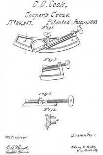
Figure 1 represents a plan view of my invention, and
Figures 2, 3, and 4 represent views of parts detached.
In the drawings —
A represents the main part of the instrurncnt, the outer edge of which is curved, to dt the inside of a barrel, and is V-shaped, as shown.
a represents a socket or groove running diagonally across it, in which iits the upper part of the cutting-iron B, which latter is made of proper form to slide easily therein.
b represents an arm extending from the upper end of the cutting-iron B, as shown, upon which is placed the shoulder b1.
b2 represents a flat spring fastened to the lower side of the iron, and extending out in line with shoulder b1.
By this arrangement a socket is made in which rests the button of screw C. The lower or cutting part of the instrument is made V-shaped, for the purpose of cutting the groove in the staves. If desired, this part may be made square in forrn, for the purpose of cutting a corresponding groove.
C represents a screw, the button of which its into the socket of the cutter B, as before described, and revolves freely therein.
c c represent its bearings, provided with corresponding screw-threads. By turning the screw C, the cutter is thrust forward or drawn back, as may be desired.
D represents another screw, placed above the cutter, and operated sirnilarly to C, excepting that it is not attached in any way to the cutter. A bearing-surface of different metal may be used if desired, for the cutter to slide upon, but this is not essential.
This instrument should be attached to the wooden guide, constructed as usual, by means of the lugs x x.
From this description the operation of my invention will be readily understood. The iron is easily attached to the screw by simply pushing the former forcibly against b2 and shoulder b1, in which case the spring b2 yields sufficiently to permit the head of the screw C to pass by the shoulder b1 and rest in the socket. When it is desired to detach the iron for any purpose, its free end should be pulled up from the croze (the holding-screw having been loosened) far enough to force spring b2 open, by which means the head of screw C is permitted to slip out. The cutter B is adjusted in or out, as may be desired, by means of the screw C, after which the screw D is set down upon it, by which means the cutter is rigidly held in place.
This construction allows the cutter to be quickly and easily detached, while at the same time it is firmly held when in use.
Having thus fully described my invention, what I claim as new, and desire to secure by Letters Patent, is —
The arm b, shoulder b1, and spring b2 of cutting-iron B, when combined and operated in connection with the head of screw C, as and for the purpose described.
This specification signed and witnessed, this third day of April, 1868.
CHARLES O. COOK.
Witnesses :
OLIVER A. PENNOYER,
G. W. FORD.


