
| PLEASE NOTE: The images presented on this page are of low resolution and, as a result, will not print out very well. If you wish to have higher resolution files then you may purchase them for only $2.95 per patent by using the "Buy Now" button below. All purchases are via PayPal. These files have all been cleaned up and digitally enhanced and are therefore suitable for printing, publication or framing. Each zip package contains all the images below (some packages may contain more), and purchased files can be downloaded immediately. |

UNITED STATES PATENT OFFICE.
_________________
CHARLES E. MITCHELL, OF NEW YORK, N. Y.
PLANE.
_________________
814,718. Specification of Letters Patent. Patented March 13, 1906.
Application filed March 26, 1902. Serial No. 100,012.
_________________
To all whom it may concern:
Be it known that I, CHARLES E. MITCHELL, a citizen of the United States, residing at New York city, county and State of New York, have invented certain new and useful Improvements in Planes, of which the following is a full, clear, and exact description.
My invention relates to planes.
Among the main objects of my invention are to provide a plane construction which is simple, inexpensive, effective, and durable. These objects I attain by the use of a new form and arrangement of parts permitting the employment of wrought or sheet metal in the formation of several of the important elements.
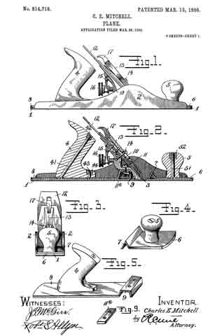
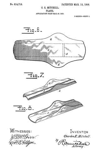
ln the drawings, Figure 1 is a side elevation of a plane embodying my invention. Fig. 2 is a longitudinal section through the same. Fig. 3 is a front elevation. Fig. 4 is a perspective view of a detail. Fig. 5 is a perspective view of another detail. Fig. 6 is a plan view of a blank. Fig. 7 is a perspective view of said blank after it has been partially formed. Fig. 8 is a perspective view of a detail of construction formed from the blank 6, and Fig. 9 is a perspective view of another detail.
The stock — that is, the body — of the plane is preferably formed of sheet metal, in which the bottom portion 1 and the sides or cheek-pieces 2 2 may be formed from a blank of a single thickness of sheet metal of proper shape — for example, such a shape as shown in Fig. 6. In the preferable construction this blank is first bent upwardly or crowned, and the sides are also bent upwardly, so as to give to the blank the shape indicated in Fig. 7. When the bottom or floor 1 is flattened down, it will cause the sides or cheek-pieces 2 2 to converge, so that they will assume practically a vertical position. Manifestly the manipulation of the metal in order to produce the desired form may be modified in various ways. ln practice it is customary to provide a transverse passage in the bottom or floor 1, termed the “throat,” through which the cutting edge of the plane-iron projects in use. The throat 3 is indicated in dotted outline in Fig. 6 and may be formed at any time, either before or after the shaping of the stock.
ln the operation of planes of any considerable size it is customary to use both hands, and to that end two handles are usually employed. ln the drawings, 4 is a rear handle, and 5 is a knob constituting a forward handle. The knob 5 may be carried upon a plate 6, which performs the double function of supporting said knob and of reinforcing and strengthening the fioor of the said stock. This plate 6 is provided, by preference, with an integral angular bend 7 at its rear edge so positioned relatively to the throat 3 as to stand closely in front of the same, as best seen in the sectional view Fig. 2. This angular bend also serves to further stiffen the floor directly adjacent to the throat. The handle 4 is carried by the plate 8, which performs the double function of supporting said handle and of reinforcing the floor 1 to the rear of the throat 3.
9 is a supporting chair or bearing, preferably formed near the forward edge of the plate 9, giving further strength to the parts and performing an additional function — to wit, that of a bearing for the frog 10, against which the plane-iron, hereinafter referred to, is clamped. ln the preferable construction the chair or bearing 9 is so formed that the frog will rest upon the rear portion thereof. The forward end of the frog 10 bears upon the floor 1 or upon an extension of the plate 8, if it is desired to extend said plate close to the throat.
11 is a screw-bolt (any desire d number may be provided) which serves to clamp the frog securely in place upon the two bearings-the floor 1 and the chair 9. The bolt 11 is so positioned that it is intermediate of said bearings and will cause the frog to hug tightly thereon, thus preventing chattering of the parts when in use. The frog 10 supports the plane-iron 12, which is clamped thereto by means of a cap-piece 13, which engages with a cap-screw 14, carried by the frog, said engagement being effected in the usual manner.
17 is a cam carried by the cap-piece 13, the same being of the usual construction and performing the usual function — to wit, putting the parts under such tension as to properly clamp the cap-piece and plane-iron against the frog.
15 is a lever carried by a portion of the frog and operated by an adjusting-nut 16, a portion of the lever engaging the plane-iron, so that by means of the nut 16 said plane-iron may be adjusted accurately in the usual way.
I preferably employ a long plate 11a in place of an ordinary nut to coact with the screw-bolt 11. This is a preferable construction, because usually two screw-bolts are employed, both of which may engage with said plate 11a , which gives abroad bearing against the under side of the angular portion formed in the plate 8.
The plates 6 8 may be secured in place against the floor 1 in any well-known manner. One method of attaching the plates is shown in Fig. 3, in which the sides 2 2, close to the floor 1, may be milled out or undercut, and the edges of the plates 6 8 may be correspondingly beveled to take into said undercut recesses. Thus by making a tight fit the plates 6 8 may be driven tightly into place to reinforce and strengthen the floor. The handles 4 5 may be secured in any desired way; but by preference I secure them by means of rivet-bars 41 and 51, respectively. The heads of said rivet-bars engage in countersunk openings in the plates 8 6, respectively, while nuts 42 52 at the upper ends of said rivet-bars serve to clamp the handles 4 5 thereon, respectively.
Additional clamping devices may be employed-for example, a screw-bolt 43, having a nut 44. By this arrangement it will be observed the superposed parts may be securely fastened to the floor without projecting through the same, thus avoiding any danger of marring the wood upon which the plane is used by reason of any irregular projections from the under side of the plane, the surface of which should be smooth and even.
Various modifications may be made without departing from the spirit and scope of my invention, the essential feature of which is to provide a plane of such a construction that sheet metal may be utilized to form the stock or body portion thereof, which stock or body portion will possess all of the advantages of a cast-metal stock in addition to the advantages inherent in the use of sheet metal. This invention permits the use of comparatively thin sheet metal in forming the stock, since the floor is of duplex construction, giving to it the desirable or necessary thickness and strength.
What I claim is —
1. A plane comprising, a body formed of sheet metal and having a sole portion and integral upturned reinforcing-flanges forming the sides, a reinforcing and strengthening plate secured between the side flanges having a stiffening-rib adjacent the throat and a handle separately formed but secured to said reinforcing-plate.
2. A plane comprising a body portion having a sole and sides of sheet metal integral therewith and reinforcing and strengthening plates secured in place against the top of the sole and between the sides having stiffening-ribs adjacent the throat and handle members for said plates, a frog mounted above one of said plates and means for adjusting said frog.
3. A plane comdprising a body portion having a sole and sides of metal integral therewith, and a reinforcing and strengthening piece situated above the sole and between the sides, a chair portion integral therewith between the said sides and supported above the sole leaving a space beneath the seat of the chair, and a separate frog mounted on said chair and secured thereto.
4. A plane comprising a body portion formed of sheet metal and having a sole and sides integral therewith, a sheet-metal chair portion supported by the sole and mounted between the sides, a frog supported on said chair, a pair of securing-screws passing through said frog and said chair and a single plate having screw-threaded openings to act as a nut for both of said securing-screws.
5. A plane comprising, a body portion with integral upturned side flanges, a chair portion supported by the sole and mounted between the sides having a recess below the same, afrog mounted on said chair, a plurality of securing-screws passing through said frog, and the top of said chair, and a plate having screw-threaded openings mounted in the recess beneath said chair and coacting with all of the adjusting-screws.
6. A plane comprising a body portion formed of sheet metal and having a sole and integral side flanges, a reinforcing-plate mounted in a groove in the said side flanges and immediately above the sole portion but resting thereon, a chair portion integral with the reinforcing-plate and a frog mounted on the chair portion and secured thereto.
7. A plane comprising a body portion of sheet metal having a sole and upturned flange portions, a reinforcing-plate secured between said side flanges and coacting with the upper surface ofthe sole portion, a supporting-chair formed integrally with the reinforcing-plate and mounted between the side flanges and a frog mounted upon the said chair.
8. A plane comprising the combination of a body portion having upwardly-extending reinforcing side flanges and a throat between said flanges, means for mounting a plane-iron and a reinforcing-plate supported above the bottom of said body portion and having an integral bend or reinforcing portion 7 immediately in front of said throat.
Signed at New York this 25th day of March, A. D. 1902.
CHARLES E. MITCHELL.
Witnesses:
R. C. MITCHELL,
ROBT. S. ALLYN.