
| PLEASE NOTE: The images presented on this page are of low resolution and, as a result, will not print out very well. If you wish to have higher resolution files then you may purchase them for only $2.95 per patent by using the "Buy Now" button below. All purchases are via PayPal. These files have all been cleaned up and digitally enhanced and are therefore suitable for printing, publication or framing. Each zip package contains all the images below (some packages may contain more), and purchased files can be downloaded immediately. |
UNITED STATES PATENT OFFICE.
_________________
HENRY B. SARGENT, OF NEW HAVEN, CONNECTICUT, ASSIGNOR TO SARGENT & COMPANY,
OF NEW HAVEN, CONNECTICUT, A CORPORATION OF CONNECTICUT.
PLANE.
_________________
818,472. Specification of Letters Patent. Patented April 24, 1906.
Application filed August 15, 1904. Serial No. 220,834.
_________________
To all whom it may concern:
Be it known that I, HENRY B. SARGENT, of the city and county of New Haven and State of Connecticut, have invented new and useful Improvements in Planes, of which the following is a full, clear, and exact description when taken in connection with the accompanying drawings, which form a part thereof, and in which —
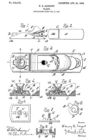
Figure 1 represents a side elevation of a plane embodying the invention; Fig. 2, a bottom view of the same; Fig. 3, an enlarged plan view; Figs. 4 and 5, longitudinal sectional views on line 4 4 of Fig. 3, the parts being shown in different positions , Figs. 6 and 7, top and side detail views, respectively, of the adjustable mouthpiece ; Fig. 8, a bottom detail view of the adjusting-cam, and Fig. 9 a transverse vertical section of the plane-bottom on line 9 9 of Fig. 3.
In all figures similar letters of reference represent like parts.
This invention relates to planes, and has for its object the production of a plane having a novel, simple, and efficient throat adjustment; and to this end it consists in the improvements and combinations of parts set forth and claimed hereinafter.
Referring to the drawings for a more particular description, the part designated by the letter A represents the plane-bottom, and B the side walls. C designates the throat, and D the frog or plane-iron seat. E designates the bit or plane-iron, and F the cap, with the cap-screw G. H is the cam-lever, I the lateral adjustment-lever, and K the adjusting-screw controlling the longitudinal adjusting-lever L. These parts may be of any suitable construction and are not part of my improvement.
As shown in Figs. 2, 4, and 5, the bottom of the plane is cut away in front of the throat for the reception of a slide or mouthpiece M. A circular perforation N is provided in the forward part of the plane-bottom with an inwardly-projecting flange O, Fig. 9. A disk P is adapted to fit in said perforation and rest on said flange and has on its under side a cam or circular depending protuberance Q, eccentric to the center of the disk. A finger-piece R projects from the periphery of the disk P, and through the center of the disk is a perforation S.
On the upper side of the slide or mouth-piece M are lugs T, distant from each other the length of the diameter of the cam Q, Figs. 4 and 5, while between them is an upwardly-projecting screw V, adapted to extend through the perforation S in the disk P for the reception of a clamping-nut W, which also forms the forward, knob of the plane. The perforation S in the disk P is considerably wider than the diameter of the screw V, so that the disk may have a limited movement about the screw without contact therewith.
The operation of the device is as follows: When it is desired to change the adjustment of the throat from the position shown in Figs. 2, 3, and 4, the clamping-nut W is slightly turned to loosen the disk P and slide M, and the disk P is turned the necessary distance by means of the finger-piece R. The cam then bears against the rear lug T on the slide M and pushes the slide rearward, as shown in Fig. 5. The slide M then contracts the throat C the desired amount, and the parts are secured by screwing the clampin-nut W down on the screw V, so that the sIide will be held against the under side of the forward end of the bottom A of the plane and the disk forced down on the flange O in the perforation N. To open the throat, it is only necessary to unscrew the nut W and loosen the parts to operate them in the reverse direction.
It will be seen that the cam depending from the disk engages the mouthpiece in an immediately adjacent plane, so that the operation is direct, and the coacting parts will be protected by the disk from dust, chips, or the like.
Having now described my invention, what I claim, and desire to secure by Letters Patent, is —
1. In a plane, the combination with a stock, of a throat in the bottom thereof, a sliding mouthpiece for varying the size of said throat, a disk fitted in a circular seat to rotate on said stock and having a depending cam between said stock and said mouthpiece adapted to engage said mouthpiece to operate the same, and protected by said disk, and means for locking said mouthpiece.
2. In a plane, the combination with a stock, of a throat in the bottom thereof, a sliding mouthpiece for varying the size of said throat, a disk fitted in a circular seat to rotate on said stock and having a depending cam between said stock and said mouthpiece adapted to engage projections on said mouth-piece in an immediately adjacent plane to operate the same, and protected by said disk, and means for locking said mouthpiece.
3. In a plane, the combination with a stock, of a throat in the bottom thereof, a sliding mouthpiece for varying the size of said throat, a disk fitted in a circular seat to rotate on said stock and having a perforation and a depending cam between said stock and said mouthpiece adapted to engage integral projections on said mouthpiece in an immediately adjacent plane to operate the same, and protected by said disk, and means for locking said mouthpiece, including a screw-threaded post on said mouthpiece projecting through said perforation in said disk, and a nut on said post adapted to bind said disk on said stock to prevent movement thereof.
4. In a plane, the combination with a stock, of a throat in the bottom thereof, a sliding mouthpiece for varying the size of said throat, a disk mounted on said stock and having a depending cam and a perforation, oppositely-disposed integral lugs on said mouthpiece adapted to be engaged by said cam, a screw-threaded post on said mouth-piece projecting through said perforation in said disk in which it is capable of lateral play, and a nut on said post adapted to bind said disk on said stock to prevent movement of said mouthpiece, the nut being arranged to overlap the wall surrounding the aperture of the disk.
5. In a plane, the combination with a stock, of a throat in the bottom thereof, a sliding mouthpiece for varying the size of said throat, a disk fitted in a circular seat to rotate on said stock and having a depending cam between said stock and said mouthpiece adapted to engage integral projections on said mouthpiece in an immediately adjacent plane to operate the same and protected by said disk, a projecting finger-piece on the upper surface of the disk, and means for locking said mouthpiece from movement.
In witness whereof I have hereunto set my hand on the 11th day of August, 1904.
HENRY B. SARGENT.
Witnesses:
L. F. BREESE,
WILLIAM A. RICE.