
| PLEASE NOTE: The images presented on this page are of low resolution and, as a result, will not print out very well. If you wish to have higher resolution files then you may purchase them for only $2.95 per patent by using the "Buy Now" button below. All purchases are via PayPal. These files have all been cleaned up and digitally enhanced and are therefore suitable for printing, publication or framing. Each zip package contains all the images below (some packages may contain more), and purchased files can be downloaded immediately. |
UNITED STATES PATENT OFFICE.
_________________
JOHN H. SHAW, OF NEW HAVEN, CONNECTICUT, ASSIGNOR TO SARGENT AND COMPANY,
OF NEW HAVEN, CONNECTICUT, A CORPORATION OF CONNECTICUT.
PLANE.
_________________
824,954. Specification of Letters Patent. Patented July 3, 1906.
Application filed April 17, 1903. Serial No. 153,092.
_________________
To all whom it may concern:
Be it known that I, JOHN H. SHAW, of the city and county of New Haven, State of Connecticut, have invented new and useful Improvements in Planes, of which the following is a full, clear, and exact description when taken in connection with the accompanying drawings, which form a part thereof, and in which —
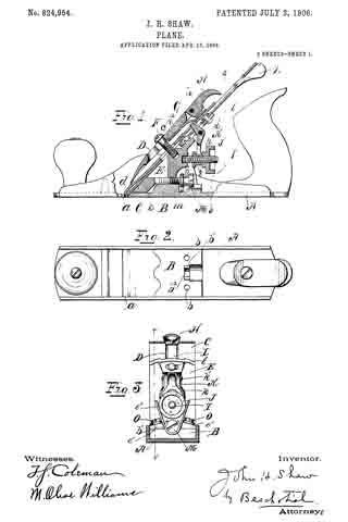
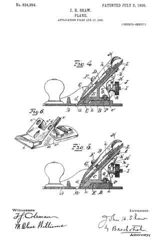
Figure 1 represents a central vertical section, the ends being shown in elevation, of a plane embodying my invention; Fig. 2, a plan view of the bed of the plane; Fig. 3, a vertical transverse section on lines 3 3 of Fig. 1; Fig. 4, a longitudinal vertical section on lines 4 4 of Fig. 3 of a portion of the plane; Fig. 5, a similar view, the bit being shown in a different adjustment; and Fig. 6 is a perspective view of the support E.
In all figures similar letters of reference represent like parts.
This invention relates to planes, and has for its object the production of a plane in which the frog may be adjusted longitudinally and clamped in place after the bit is clamped to the frog.
in the proper adjustment of the bit of a plane it is necessary to move the bit longitudinally on the frog, so that the cutting edge will project more or less through the throat of the frame according to the depth of the cut desired. When properly adjusted, it is necessary in order that the bit may be held firmly in place that its cutting end should rest against the rear of the throat and against the frog. Owing to the variations in the angle to which the bit is ground, the adjustment of the bit longitudinally on the frog may affect its position in the throat and against the frog. It is an important desideraturn, therefore, in order to prevent what is known as “chattering,” which occurs when the lower end of the bit is not held firmly against the throat and frog, that the frog may be adjusted on the frame after the bit is adjusted longitudinally on it, because were it necessary to remove the bit in order to adjust the frog a number of attempts might be required to establish the exact relation between the frog and throat and beveled end of the bit.
To this end my invention resides in the production of a novel construction by which the adjustment of the frog may be made from the rear after the bit is secured to the front face of the frog, as set forth and claimed hereinafter, together with other minor improvements.
Referring to the drawings for a more particular description, the parts designated by the letter A represent the frame or stock of the plane, and a the throat thereof, which extends transversely across the bottom.
B is a raised portion near the middle of the frame having screw-holes b and a vertical flange b’ at right angles to the plane, provided with a substantially semicircular groove b2.
C’ represents the bit or plane iron, to which is secured b the screw c the cap-iron D. The forward end d of the cap-iron D is bowed outward in well-known manner.
E is a frog or support for the bit adapted to rest on the raised portion B of the frame A and having a depending portion e, adapted to rest on the frame A immediately in the rear of the throat a.
F is a screw projecting from the front of the support E, the head of which is adapted to engage and hold in place the clamping-cap G. The forward end of the clamping-cap G bears on the bowed portion d of the cap-iron D, and pivoted to the rear end of the clamping-cap is a cam-clamp H, adapted to bear on a spring-plate it to lock the cap in place between the engaging head of the screw F and the cap-iron D.
I designates a set-screw secured to said support and on which is mounted a nut J, having an annular groove j, engaged by the forked end k of a bell-crank lever K, plivoted at k’ to the support, and having its other end k2 engage the cap-iron D in well-known manner. By means of the nut J and lever K the cap-iron D and the bit C, secured thereto, are adjusted longitudinally on the forward inclined face of the support E.
L is a lever pivoted to the support at l, adapted to engage the screw c, connecting the bit C and cap-iron D. By means of the lever L the bit may be adjusted transversely in well-known manner.
M is an adjusting-screw adapted to be screwed into the rear of the support and having on its head an annular groove m, adapted to be engaged by a flange b’ on the frame of the plane. The support E has lateral projecting portions e’ upon its respective sides and preferably extending to the rear of the body portion thereof, and e” designates upright arms on said projecting portions connecting with the body portion.
O designates one or more clamping-screws adapted to extend through longitudinal slots P in the projecting portions of the support and engage in internally-threaded screw-holes b in the frame.
By this construction it is possible to adjust and clamp the support in place after the bit is properly mounted on the support, for after the bit is so mounted the clamping-screws O may be loosened and the support moved forward or backward by the adjusting-screw M.
Having now described my invention, what I claim, and desire to secure by Letters Patent, is —
1. In a plane, the combination with a frame, of a bit, a throat in said frame throihgh which said bit may project, a longitudinally-adjustable frog or support carrying the bit-adjusting means, a part carried by the support and projecting rearwardly of the bit-adjusting means, an clamping means for retaining the support in adjusted position, said clamping means being arranged to engage said projecting part of the support at a spaced distance from the body part thereof, whereby it is accessible when the bit is mounted on the support.
2. In a plane, the combination with a frame, of a bit, a throat in said frame through which said bit may project, a bodily-adjusting means, and means for clamping said support in its adjusted position carried by a rearwardly-projecting portion of the frog and accessible when the bit is mounted on said support.
3. In a plane, the combination with a frame, of a bit, a throat in said frame through which the bit may project, a movable support on said frame to the rear of said throat and carrying the bit-adjusting means, an adjusting-screw for adjusting said support longitudinally of said frame from the rear of said support, and a clamping screw or screws adapted to hold said support in its adjusted position, said screw or screws being carried by a rearwardly-projecting part of the support and accessible when said bit is in place on said support.
4. In a plane, the combination with a frame having a portion substanially parallel to the bottom thereof, of a bit, a throat in said plane through which the bit may project, a support carrying the bit-adjusting means on said frame capable of moving longitudinally on said parallel portion of said frame, a slot in a rearwardly-projecting portion of said support, and a clamping-screw passing through said slot into said frame to hold the support from movement on said frame, whereby said clamping-screw is accessible for mampulation while said bit is in place on said support.
In witness whereof I have hereunto set my hand on the 28th day of February, 1903.
JOHN H. SHAW.
Witnesses:
LE ROY J. KIRKHAM,
ALICE A. WILSON.