
| PLEASE NOTE: The images presented on this page are of low resolution and, as a result, will not print out very well. If you wish to have higher resolution files then you may purchase them for only $2.95 per patent by using the "Buy Now" button below. All purchases are via PayPal. These files have all been cleaned up and digitally enhanced and are therefore suitable for printing, publication or framing. Each zip package contains all the images below (some packages may contain more), and purchased files can be downloaded immediately. |

UNITED STATES PATENT OFFICE.
_________________
LEWIS DORUS SMITH, OF PORT HURON, MICHIGAN, ASSIGNOR TO
STANLEY RULE AND LEVEL COMPANY, A CORPORATION OF CONNECTICUT.
PLANE.
_________________
827,473. Specification of Letters Patent. Patented July 31, 1906.
Application filed March 15, 1904. Serial No. 198,203.
_________________
To all whom it may concern:
Be it known that I, LEWIS DORUS SMITH, a citizen of the United States, residing at Port Huron, county of St. Clair, State of Michigan, have invented certain new and useful Improvements in Planes, of which the following is a full, clear, and exact description.
My invention relates to improvements in planes, and particularly to a plane which is adapted to carry any one of a large variety of cutters or plane-irons. A plane of the same general class is shown in the United States Letters Patent No. 532,84.
The object of my invention is to construct a plane which shall be efficient and readily interchangeable and adjustable for different classes of work. I have also sought to make the construction as simple as possible, so that the adjustments and interchanges may be effected easily, and the cost of manufacture may be reasonable. I have also sought to construct a plane which shall be useful in connection with classes of work hitherto impossible to planes of this type.
A plane embodying my invention is shown in the accompanying single sheet of drawings. Two parts of the plane are adjustable laterally with relation to one another and adapted to carry a plane-iron. Between the two adjustable portions is located a gage for limiting the cutting depth of the iron. This gage is adjustable vertically and laterally and is readily removable. When desired , an auxiliary guide may be employed.
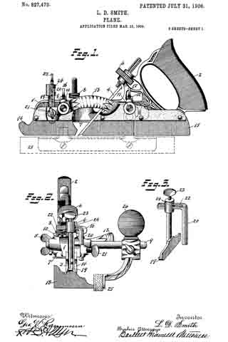
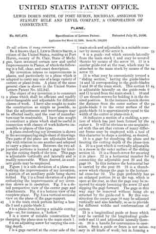
Figure 1 is a side elevation of a plane embodying the improvements of my invention, a portion of an auxiliary guide being shown dotted. Fig. 2 is a front elevation of a plane embodying the improvements of my invention shown as in operation. Fig. 3 is a detail perspective view of the center gage and attachments. Fig. 4 is a bottom view of the complete plane. Fig. 5 is a vertical sectional view on the plane of the gage-support.
1 is the main stock portion having a handle 2 and a guide-blade 3.
4 is a plane-iron, having a suitable cutting edge — as, for instance, a “hollow.”
5 is a screw of suitable construction for clamping the plane-iron to the main stock 1.
6 is an adjusting screw for varying the cutting depth.
7 is a gage carried at the outer side of the main stock and adjustable in a suitable manner by means of the screw 8.
9 is a guide-rod which extends laterally from the main stock 1 and may be secured thereto by means of the screw 10. 11 is a similar guide-rod at the rear, which may be attached to the main stock by means of the screw 12.
13 is what may be conveniently termed a “sliding section,” having the guide-blades 14 and 15 corresponding to the guide-blades 3 and 30 of the main stock. This section 13 is adjustable laterally on the guide-rods 9 and 11 to and from the main stock 1. 16 and 17 are thumb-screws for holding it in the desired position. In the instance herein shown the distance from the outer surface of the guide-blade 3 to the outer surface of the guide-blade 14 is approximately equal to the width of the cutter or plane-iron 4.
18 indicates a section of a molding, a portion of which has just been formed by the cutter 4. It will be obvious to one acquainted with this art that cutters of many different forms may be employed with a tool of this character to shape a molding, as desired.
19 is a gage for steadying the plane and limiting the cutting depth of the plane-iron 4. 20 is a post which is vertically adjustable in a recess in the outer surface of the sliding section 13. 21 is a thumb-screw for securing it in place. 22 is a horizontal member for connecting the adjustable post 20 and the gage 19. In this instance the horizontal bar is carried by the post 20. 23 is a thumb-screw which clamps the gage to the horizontal cross-bar 22. The gage preferably has an enlarged portion 24 at the top, which is open at the rear, so that the gage may be removed by simply loosening the screw 23 and slipping the gage forward. The gage in this way may be removed without being obstructed by the guide-rod 9. By this construction the center gage 19 may be adjusted vertically and also laterally, so as to provide for different widths and conformations of cutters.
25 is a longitudinal guide or fence which may be carried by the longitudinal guide-rods 9 and 11 and adjustable laterally thereon. 26 is a handle for convenience in operation. Such a guide or fence is not necessary in all kinds of work; but in forming a molding, as herein illustrated, it is advantageous.
What I claim is —
1. In a plane, the combination of a handle member, a sliding section member adjustable relatively thereto, a laterally-projecting lug carried by one of said members and having a vertical passage-way, a post passing through and vertically adjustable in said passage-way, a laterally-extending thumb-screw passing through said lug for coacting with said post, and a center gage located between said members and means for supporting said gage from said vertical post.
2. A plane-gage attachment of the character described comprising the combination of two substantially parallel rods, a shoe member carried by one of said rods, a connecting member having one endf fixedly secured to one rod and an adjustable clamping means carried by the other rod for engagement with said member and having an open horizontal slot, substantially as described for the purpose specified.
3. A plane-gage attachment of the character described, and for the purpose specified, comprising the combination of two substantially parallel rods spaced apart from each other, a shoe member carried by one of said rods, a laterally-projecting connecting member having one end fixedly secured to one of said rods, the other rod being laterally adjustable upon the connecting member of the first rod, and means for clamping the second rod upon said connecting member.
Signed at Port Huron, Michigan, this 5th day of March, 1904.
LEWIS DORUS SMITH.
Witnesses:
S. V. JONES,
LEWIS ATKINS.