| PLEASE NOTE: The images presented on this page are of low resolution and, as a result, will not print out very well. If you wish to have higher resolution files then you may purchase them for only $2.95 per patent by using the "Buy Now" button below. All purchases are via PayPal. These files have all been cleaned up and digitally enhanced and are therefore suitable for printing, publication or framing. Each zip package contains all the images below (some packages may contain more), and purchased files can be downloaded immediately. |
United States Patent Office.
PHILANDER S. FOSTER, OF RICHMOND, MAINE.
Letters Patent No. 86,295, dated January 26, 1869.
_________________
IMPROVEMENT IN BENCH-PLANES.
_________________
The Schedule referred to in these Letters Patent and making part of the same.
_________________
To all whom it may concern:
Be it known that I, PHILANDER S. FOSTER, of Richmond, in the county of Sagadahoc, and State of Maine, have invented a new and valuable Improvement in Bench-Planes; and I do hereby declare that the following is a full, clear, and exact description of the construction and operation of the same, reference being had to the annexed drawings, making a part of this specification, and to the letters and figures of reference marked thereon.
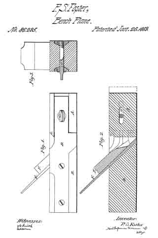
Figure 1, of the drawings, is a side view of my bench-plane;
Figure 2 is a longitudinal section; and
Figure 3 is a cross-section of the same.
My invention relates to that class of bench-planes constructed partly of wood and partly of metal; and It consists in providing a remedy against the difficulty commonly called choking, by means that are more permanent and efficient than have heretofore been devised.
By my device, also, a wider bit may be used, and consequently a wider shaving be cut, than by the ordinary bench-planes.
The letter A, of the drawings, represents the removable and adjustable wooden front of the plane, and the letter B is the wooden rear thereof.
The part A is constructed with a slot in its middle, running lengthwise, as shown on fig. 2, adapted to hold and operate with the thumb-screw C. This slot is marked H on the drawings.
The letters D are metallic plates, adjusted respectively on each side of the wooden parts of the plane, in the manner shown on figs. 1 and 3.
That portion of these metallic side plates respectively which is adjusted forward of the bit and throat, is constructed in a bevelled form, as shown on fig. 3, and is adapted to corresponding grooves, out in the sides of the part A, in which grooves it is held securely and firmly by the thumb-screw C, in conjunction with its bevelled form so resting in its grooves.
The part A is cut off square at its rear end, leaving a small bevel at the point c, upon which the hammer may be used.
I sometimes also arrange metallic boxings in the grooves of the part A, adjusted to the plates D. These boxings will save the wear of the wood, and when properly oiled, will aid in the adjustment of said part to the bit of the plane.
The thumb-screw G passes through both plates D and the slot H, and serves as a means of tightening, loosening, and fastening the part A, at the will of the operator.
The letter E is the bit, and letter F is the wedge of the plane. These are adjusted in diagonal slots, formed in the inner sides of the plates D respectively, in the manner shown on fig. 2.
The fact that the bit and wedge are adjusted in plates of metal, instead of the wooden throat of the plane, as is usual, justifies the manufacturer in adapting a bit to the plane, that shall be wider, and consequently shall out a wider shaving than is prudent in planes wherein the bit is adjusted in wood only.
It will readily be perceived that by the upright formation of the rear end of part A, the plane is provided with a large open throat, which greatly lessens the danger of choking, and that in case such an event occurs, the chips in the throat may be easily loosened and removed, by moving the part A forward. This movement is effected by unscrewing the thumb-screw C, and striking a gentle blow with a hammer on the bevel c.
What I claim as my invention, and desire to secure by Letters Patent, is —
A bench-plane, having bevelled metallic side plates D, wooden sections A and B, slot H, and thumb-screw C, when the same are constructed and arranged as specified.
In testimony that I claim the above, I have hereunto subscribed my name, in the presence of two witnesses.
PHILANDER S. FOSTER.
Witnesses :
WM. S. HAGAR,
WM. H. STUART.


