| PLEASE NOTE: The images presented on this page are of low resolution and, as a result, will not print out very well. If you wish to have higher resolution files then you may purchase them for only $2.95 per patent by using the "Buy Now" button below. All purchases are via PayPal. These files have all been cleaned up and digitally enhanced and are therefore suitable for printing, publication or framing. Each zip package contains all the images below (some packages may contain more), and purchased files can be downloaded immediately. |
UNITED STATES PATENT OFFICE.
_________________
GEORGE HUNTER BARTLETT, OF BUFFALO, NEW YORK, ASSIGNOR TO THE STANLEY RULE &
LEVEL COMPANY, OF NEW BRITAIN, CONNECTICUT, A CORPORATION OF CONNECTICUT.
PLANE.
_________________
865,560. Specification of Letters Patent. Patented Sept. 10, 1907.
Application filed May 21, 1907. Serial No. 374,960.
_________________
To all whom it may concern:
Be it known that I, GEORGE HUNTER BARTLETT, a citizen of the United States, residing at Buffalo, Erie county, New York, have invented certain new and useful Improvements in Planes, of which the following is a full, clear, and exact description.
My invention relates to improvements in planes, and particularly to that type of a plane termed a router, a tool which is used by carpenters, cabinet-makers, stair-builders, pattern-makers and wheelwrights. The function of the same is to rout out and smooth the bottom of grooves, panels and other depressions below general surfaces of woodwork.
The object of the invention is to provide an attachment whereby the tool may be converted from the open-throat plane to the closed-throat plane, the attachment being so mounted that it may be adjusted to a nicety. Beyond this the attachment is also so mounted that any adjustment of the bit or cutter will not disturb the same.
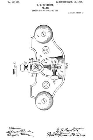
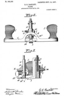
In the accompanying drawings Figure 1 is a plan view; Fig. $2 is a front elevation; and Fig. 3 is a vertical section taken through the middle of the plane.
1 is the main body or stock. 2–2 are the handles at opposite ends thereof. The stock or body 1 is cut partially through on its lower side to form the throat, in which the bit or cutter 3 stands, projecting forwardly therein, as best seen in Figs. 1 and 3.
4 is an arched bridge overstanding the forward end of the throat and uniting the two sides of the stock as best seen in Figs. 1 and 2.
5 is a stationary bearing post for the shank of the cutter or bit. Ordinarily the shank of a cutter is square in cross section and the forward side of the post 5 should, therefore, be shaped approximately thereto to furnish a superior support. The rear side of the post may also be flattened or grooved to receive the forward end of a lock-screw 6 carried by a collar 7, which extends around the post 5 and engages the shank of the cutter 3, as best seen in Fig. 1.
8 is a screw-threaded extension on the post 5, upon which extension is mounted a correspondingly screw-threaded adjusting nut 9, the edge of which makes a connection with the shank of the cutter so that by loosening up on screw 6 and adjusting the nut 9 up and down, the cutter can be raised and lowered to project to the desired depth below the sole of the body.
10 is a bracket preferably formed integrally with the arch or bridge 4.
11 is a set-screw for the bracket 10.
12 is a vertically adjustable post mounted in the bracket 10 and carrying at its lower end what I term a throat-closer or adjuster 14, which latter may, if desired, be detachably secured to the post 12 by means of a collar 14a and binding-screw 15.
The bracket 10 is preferably formed at the rear of the bridge or arch 4.
For certain kinds of work it is preferable to have a closed throat while for other kinds of work it is preferable to have an open throat. With my improvement the plane may be converted into one or the other at will. The adjustment up and down for the cutter in no way affects or disturbs the correct position of the member 14 after the latter has once been adjusted. By separating these parts and making them entirely independent, to wit, the adjustment for the cutter and the adjustment for the member 14, much unnecessary labor is avoided and a superior structure afforded.
The form of the bracket 10 may, of course be modified in many ways, similar clamping means to those shown to the rear for the cutter, being permissible.
What I claim is —
1. A router plane comprising a frame or body, a throat entering the same at one side thereof, a bridge for the open end of said throat, a cutter and means for holding the same at the rear of the throat, a throat adjuster and a bracket on said bridge for holding the adjuster in said throat forward of the cutter.
2. A router plane comprising a body or frame, a throat extending into the same at one side, an arched bridge connecting the opposite sides of the body near the forward end of the throat, a cutter, means for adjustably supporting said cutter at the rear of said throat, a throat-adjuster, a bracket on said bridge for supporting said adjuster.
GEORGE HUNTER BARTLETT.
Witnesses:
NORMAN O. DE BOCK,
FRANK C. FERGUSON.


