| PLEASE NOTE: The images presented on this page are of low resolution and, as a result, will not print out very well. If you wish to have higher resolution files then you may purchase them for only $2.95 per patent by using the "Buy Now" button below. All purchases are via PayPal. These files have all been cleaned up and digitally enhanced and are therefore suitable for printing, publication or framing. Each zip package contains all the images below (some packages may contain more), and purchased files can be downloaded immediately. |
UNITED STATES PATENT OFFICE.
_________________
OWEN J. SUND, OF TACOMA, WASHINGTON.
ADJUSTABLE PLANE.
_________________
895,796. Specification of Letters Patent. Patented Aug. 11, 1908.
Application filed May 16, 1907. Serial No. 373,931.
_________________
To all whom it may concern:
Be it known that I, OWEN J. SUND, a citizen of the United States, residing at Tacoma, in the county of Pierce and State of Washington, have invented certain new and useful Improvements in Adjustable Planes; and I do hereby declare the following to be a full, clear, and exact description of the invention, such as will enable others skilled in the art to which it appertains to make and use the same.
This invention relates to improvements in planes and particularly to adjustable planes of the type known as “carpenter’s nosing planes.”
The invention comprises the production of a cutter-holder and means for varying the width at which the same is designed to operate.
The invention further comprises the production of a plurality of cutter-holders that are designed to register with each other for providing means for varying the width of cut of the cutters.
The invention still further comprises the production of a plurality of cutter-holders designed to be adjustably secured together, and means for varying the adjustment, for regulating the width of cut desired.
The object in view is the production of a plane for forming rounded edges that may be adjusted to any desired width and without changing the cutting tools used.
A still further object of the invention is the production of a nosing plane formed in a plurality of parts, and means for adjustably securing same together, and cutters that are designed to extend past each other, in order to form a cutting surface of varying width.
With these and other objects in view, the invention comprises certain other novel constructions, combinations and arrangements of parts as will be hereinafter more fully described and claimed.
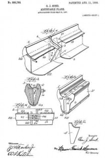
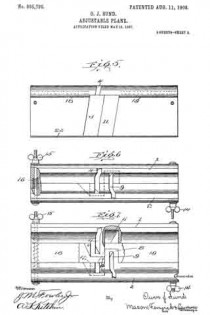
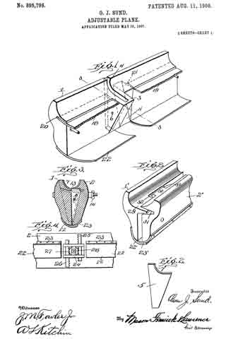
In the accompanying drawing:–Flgure 1 is a perspective view of one of the cutter-holders and surrounding parts. Fig. 2 is a side elevation of a cutter forming part of the present invention. Fig. 3 is a cross-section through a plane constructed according to the present invention the section being taken on the line 3–3 of Fig. 1. Fig. 4 is a detail fragmentary bottom plan view of a plane formed according to the present invention, an adjusting device being seen in connection therewith. Fig. 5 is a side elevation of one of the cutter-holding members. Fig. 6 is a bottom plan view of a plane formed according to the present invention the cutters being removed. Fig. 7 is a bottom plan view of a plane the cutters being removed, said plane being adjusted to its extreme position, certain parts being broken away to better disclose the invention. Fig. 3 is a detail fragmentary perspective view of a slightly modified form of the present invention.
In constructing a plane according to the present invention, I provide a pair of cutter-holding members 1 and 2. Member 1 has formed integral therewith an extension 3, as clearly seen in Fig. 1, for accommodating a slot 4, which is designed to extend from the outer edge of member 3 to the outer edge of member 1. Slot 4 is designed to be of such a shape and depth as to accommodate cutter 5. An adjusting screw or clamping member 6 is screw-threaded into member 3 and is designed to extend entirely through one of the walls of the same and engage cutter 5 for holding the same in position for having its cutting edge 7 project a short distance above the surface of the members 1 and 2. Member 2 is made similar to member 1 and has provided an extension 3 similar to extension 3 which is designed to accommodate a slot 9 similar to slot 4 in which a knife, as 5, is designed to be inserted and held in place by a suitable clamping member 10. Member 8 is designed to fit into a hollowed-out portion 11 in member 1 and member 3 is designed to iit into a hollowed-out portion 12 of member 2, when members 1 and 2 are in their closed position, as seen in Fig. 1, or when in a partially closed position. When in a closed position a semi-circular portion 13 is formed between members 1 and 2, as clearly seen in Fig. 3 for forming a rounded edge upon any board or other device that is designed to have the edges rounded. As seen in Fig. 3 the curved portion 13 is semi-circular in cross-section and the plane will cut or round the edge of any board or material to which the same is applied. If the material requires it the curved part 13 members 1 and 2 may be moved apart by unscrewing thumb screws 14 and 15. When thumb screws 14 and 15 are screwed outward, springs 16 will force outward member 22 to any desired distance, as, for instance, seen in Fig. 7. Though the members 1 and 2 are thus forced apart, a cutting surface is provided for the space between the same, as cutting members 5, located in slots 4 and 9, pass each other, as clearly seen in Fig. 7, for providing a continuous cutting edge regardless of the distance apart of members 1 and 2. By this construction one set of knives, as 5, will cut or round the edges of boards, planks, and the like, of various widths or thicknesses, without changing the cutting knife. In order to form a bottom or surface for taking place of the surface 13, when members 1 and 2 are moved apart, I provide sliding members 18 and 19, which are accommodated in slots 20 and 21.
Positioned on the opposite side or bottom to the cut out portion or depression 13 are members 22 and 23, which are designed to overlap and form a support for the hands of the operator, when using the plane, so that the operator will not be under any danger of accidentally placing his hand between members 1 and 2 during the operation of the device. Members 22 and 23 also form a smooth, even surface, against which the hands of the operator may press when using the plane.
When moving members 1 and 2 from the position shown in Fig. 6, thumb screws 14 and 15 are unscrewed or moved outward, and springs 16 normally force outward the members against which the same are designed to press, but in order to form a more positive operation of forcing apart and holding in the extended position, I provide adjusting member 24. Adjusting member 24 is preferably placed upon the top of the plane and is composed of reciprocating members 25 and 26 that are secured to members 1 and 2, respectively. Members 25 and 26 are provided on one edge with a rack bar for engaging a gear wheel 27, which is designed to be revolved by a suitable hand wheel 28. When springs 16 fail to work and when it is desired to positively hold in an extended position members 1 and 2, hand wheel 28 is revolved, and in turn forces outward members 25 and 26, which are secured respectively to members 1 and 2.
In constructing a device according to the present invention, slots 4 and 9 may be made at any desired angle for accomplishing the desired result, and members 1 and 2 may be made of any desired material, but are preflerably made from a good quality of steel.
Referring more particularly to Fig. 8, it will be observed that I form the same in a slightly modified way the way I form members 1 and 2 of the preferred construction. Members 1′ and 2′ are formed with projections 29 and 30 on the inner surface, which are designed to fit into slots or depressions 31 and 32. This is designed to take the place of members 18 and 19 and for guiding members 1′ and 2′ in their movement and to form a sort of false bottom. Suitable overlapping members 22′ and 23′ are used on the back of the plane, similar to the members 22 and 23.
What I claim is:
1. In a plane, a plurality of cutting-holders overlapping, cutters adjustably secured therein, their cutting edges adjoining each other and arranged in parallel lanes and means for varying the position of the cutter holders.
2. A plane, comprising a plurality of cutter-holders overlapping, cutters positioned therein their cutting edges adjoining each other and arranged in parallel planes, means for varying the position of said cutter-holders, and means for guiding said cutter-holders in their various positions.
3. A plane, com rising a plurality of cutter-holders, formed with a cut out portion and a projection, the projection of one cutter-holder being adapted to register with the cut out portion of the corresponding cutter-holder, overlapping cutters positioned therein, their cutting edges adjoining each other and arranged in parallel planes and means for holding said cutter-hollders in operative position.
4. A plane, comprising a plurality of cutter-holders, said cutter-holders being formed with a cut out portion and a projecting portion, the projecting portion of one cutter-holder being adapted to register with the cut out portion of the other cutter-holder, said cutter-holders being formed with slots that extend into said projections, overlapping cutters positioned therein, their cutting edges adjoining each other and arranged in parallel planes, and means for adjusting the cutter-holders to various positions for varying the cut of said cutters.
5. A plane comprising a plurality of transverse cutter holders formed with overlapping portions, overlapping cutters positioned therein, the edges of said cutters being arc-shaped, and means for forcing apart said cutter holders in planes parallel with each other for varying the widlfh of the cut, the shape of the cutters permitting the separation of the same without changing the shape of the cut.
6. A plane, comprising a plurality of cutter-holders, overlapping cutters positioned therein, their cutting edges adjoining each other and arranged in parallel planes, and means for forcing apart said cutters, said means comprising a plurality of rack bars, a gear wheel for operating said rack bars, a hand wheel for operating said gear wheel, and means for holding said gear wheel in contact with said rack bars.
7. A plane, comprising a plurality of cutter-holders, overlapping cutters mounted therein, their cutting edges adjoining each other and arranged in parallel planes, a set screw for holding the same in any desired position, and means for regulating the distance between said cutter-holding members.
8. A plane, comprising a plurality of cutter-holders, overlapping cutters positioned in said holders the edges of said cutters being segment shaped, means for varying the distance between said cutter-holding members, and longitudinal overlapping strips secured to said cutter-holding members on the edges opposite the cutting edges.
In testimony whereof I affix iny signature in presence of two witnesses.
OWEN J. SUND.
R. D. SHUTT,
W. G. HEINLY.

