| PLEASE NOTE: The images presented on this page are of low resolution and, as a result, will not print out very well. If you wish to have higher resolution files then you may purchase them for only $2.95 per patent by using the "Buy Now" button below. All purchases are via PayPal. These files have all been cleaned up and digitally enhanced and are therefore suitable for printing, publication or framing. Each zip package contains all the images below (some packages may contain more), and purchased files can be downloaded immediately. |
UNITED STATES PATENT OFFICE.
_________________
DAVID JAMES, OF COFFEYVILLE, KANSAS.
OIL-CUP FOR PLANES.
_________________
940,324. Specification of Letters Patent. Patented Nov. 16, 1909.
Application filed June 22, 1907. Serial No. 580,239.
_________________
To all whom it may concern:
Be it known that I, DAVID JAMES, citizen of the United States, residing at Coffeyville, in the county of Montgomery and State of Kansas, have invented new and useful Improvements in Oil-Cups for Planes, of which the following is a specification.
My invention relates to improvements in oilers for planes.
The object of my invention is to provide a device of the character described, in which the lower face of the plane can be supplied with the proper amount of oil, and by which the oil supply opening can not be filled with dirt and prevent the proper operation of the oiler. Neither will the oil run from the oil cup when the plane is inverted.
Another object of my invention is to provide a more simple, cheap and effective oiler of this character to accomplish the result desired.
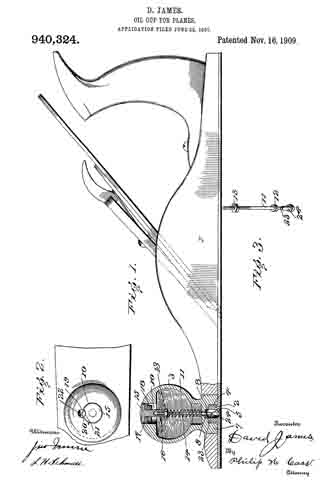
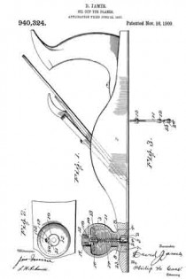
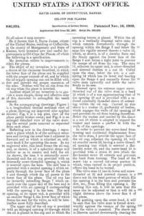
ln the accompanying drawings: Figure 1 is a longitudinal vertical sectional view of a plane, showing my improved oiler applied thereto; Fig. 2 is a top plan view of the plane partly broken away; and Fig. 3 is an enlarged detached view of the valve showing the several parts removed or separated from each other.
Referring now to the drawings, 1 represents a plane which is of the ordinary structure and having the usual boss 2 adjacent its forward end to which is attached an ordinary knob 3 for operating the same. In my improved oiler, this knob forms the oil cup, and, as shown, is of a spherical shape and hollow so as to receive and hold the oil. As shown, the boss 2 is externally screw-threaded and the oil cup provided with an internally screw-threaded opening 4, which is screwed upon the boss. The said boss is provided with a central opening 5 which extends through the lower face of the plane 6 and through which the oil passes to the lower face of the plane. The oil cap has an inwardly extending flange 7 which extends over the upper end of the boss and is provided with an opening 8 corresponding with the opening 5 in the boss. The said opening, at its upper end, is provided with an annular flange 9, the lower face of which forms the seat for the valve, as will be hereinafter more fully described.
The upper end of the oil cup is provided with an enlarged opening 10 through which the oil is placed in the cup and in which the operating button is placed. Within the oil cup is a vertically disposed valve stem 11 which extends downwardly through the opening within the flange 9 and below the same has rigidly secured thereto a valve 12, which, as shown, is of a circular form and fits firmly against the lower face of the flange 9 and forms a tight joint to prevent the escape of oil from the cup. The stem 11, adjacent its upper end, is screw-threaded and screwed thereon is a nut 13. Coiled upon the stem, below the nut, is a coil-spring 14 which has its lower end bearing upon the flange 9 and normally forces the valve stem upwardly and holds the valve firmly to its seat.
Screwed upon the extreme upper screw-threaded end of the valve stem is a head 15 which is of a size approximating that of the opening 10 and is provided with a reduced externally threaded sleeve 16 extending within the oil cup. Carried by this sleeve is a washer 17, preferably of leather, which engages the walls of the opening 10 and prevents the oil from leaking therefrom. Below the washer and carried by the sleeve is a nut 18 which is adapted to expand the washer and insure a perfect fit with the walls of the openings.
In order to prevent the screw-head from turning and accidental displacement from the valve stem, I provide the upper face of the oil cup, adjacent the opening 10, with an annular recess 19, having a screw-threaded opening into which is screwed a flat-headed screw 20, and the screw-head 15 is provided with a recess 21 into which the flat-headed screw 20 extends and prevents the head from turning. The head of the screw has a curved cut-away portion 22 which, when turned in its proper position, allows the head to be turned.
The valve stem 11 has its lower end screw-threaded at 23 and screwed thereon is a sleeve nut 24, the head portion of which fills the opening 5 in the boss and prevents the dirt, etc., from filling this opening 5. By turning this nut, it will be seen that the same can be adjusted so that it will hit a slight distance above the lower face 6 of the plane.
By pushing upon the screw-head, it will be seen that the valve stem is forced downwardly against the tension of the spring and the valve is unseated. The sleeve nut is likewise carried downwardly clearing the opening 5 of all the dirt and allows the oil to freely flow downwardly to the lower face of the plane. When the screw-head is released, it resumes its normal position and should the plane be inverted no oil will leak therefrom.
Having thus fully described my invention, what I claim as new and desire to secure by Letters Patent, is:
1. The combination with a plane, of an oil cup attached to the upper face of the plane and in communication with the lower face of the plane, a valve controlling the flow of oil from the cup, and a plug carried by the valve for preventing the communication from being filled with dirt.
2. The combination with a plane, of an oil cup attached to the upper face of the plane and in communication with the lower face of the plane, the cup having a filling opening therein, a valve controlling the upper end of the lower communication, a plug carried by the valve for closing the lower end of said opening, a valve stem carried by the valve and extending within the filling opening, and a head within the filling opening for closing the same and adapted to operate the valve stem.
3. The combination with a plane, of an oil cup attached to the upper face of the plane and in communication with an opening through the plane, the oil cup having a filling opening, a head closing said opening and having a screw-threaded sleeve extending within the oil-cup, an elastic washer carried by the sleeve and engaging the walls of the filling opening, a nut on said sleeve for expanding the washers, a valve stem screwed within the sleeve, a valve carried by the stem and controlling the opening through the plane, and means carried by the stem for preventing the last named opening from being filled with dirt.
4. The combination with a plane, of an oil cup attached to the upper face of the plane and in communication with an opening through the plane, the oil-cup having a filling opening, a head closing said opening and having a recess in its upper face, a screw carried by the oil-cup and having its head extending within the recess, the said head having a cut-away portion to correspond with the curvature of the screw-head, a sleeve carried by the head and extending within the oil cup, an elastic washer carried by the sleeve and engaging the walls of the filling opening, a nut on said sleeve for expanding the washer, a valve stem screwed within the sleeve, a flange surrounding the opening through the plane and forming a valve seat on its lower face, a valve carried by the stem, a spring surrounding the stem between the sleeve and the flange and normally holding the valve stem upward with the valve seated, and a screw sleeve screwed upon the lower end of the valve stem and normally filling the lower end of the opening extending through the plane for preventing the same from being filled with dirt.
5. The combination with a plane, of an oil cup attached to the upper face of the plane and in communication with the lower face thereof, a vertically disposed valve stem within the oil cup and having a valve carried thereby and working in combination with a valve seat within the cup, and a plug carried by the lower end of the valve stem and closing the communication between the oil cup and the lower face of the plane.
6. The combination with a plane, of an oil cup attached to the upper face of the plane and in communication with the lower face thereof, a vertically disposed valve stem within the oil cup and having a valve carried thereby and working in combination with a valve seat within the cup, a valve stem carried by the valve and extending into the filling opening, a head closing the filling opening and adapted to operate the valve stem, a plug carried by the lower end of the valve stem within the communication between t.he oil cup and the lower face of the plane, and means connected to the valve stem for normally holding it in an upward position with the plug flush with the lower face of the plane.
In testimony whereof I have affixed my signature, in presence of two subscribing witnesses.
DAVID JAMES.
Wittnesses:
J. B. ELLIS,
N. M. JANSSEN.


