No. 668,299 – Spokeshave (Justus A. Traut) (1901)

[paiddownloads id=”551″]668299


UNITED STATES PATENT OFFICE.

_________________

JUSTUS A. TRAUT, OF NEW BRITAIN, CONNECTICUT.

SPOKESHAVE.

_________________

SPECIFICATION forming part of Letters Patent No. 668,299, dated February 19, 1901.
Application filed October 29, 1900. Serial No. 34,012. (No model.)

_________________

To all whom it may concern:

Be it known that I, JUSTUS A. TRAUT, a citizen of the United States, residing in New Britain, in the county of Hartford and State of Connecticut, have invented certain new and useful Improvements in Spokeshaves, of which the following is a specification.

This invention relates to spokeshaves, and has for one object the provision of an improved tool which may be employed on various varieties of wood with good results and one in which the knife and the guard or throat-gage are adjustable in planes at right angles to each other; the back of the guard being formed with a plane face constituting a wall of the throat for the reception of the shavings, whereby the straight edge of said guard opposed to the knife may when injured or blunted be readily renewed by simply grinding said face.

A further object of the invention is the provision within the stock of the spokeshave of a chamber for the reception of shavings, the upper wall of said chamber being curved outwardly to facilitate the discharge of said shavings.

A further object of the invention is the provision, in connection with a spokeshave, of a guard or throat-gage, the working surface of which is convex both transversely and longitudinally.

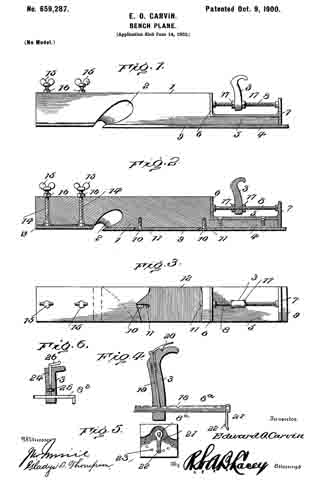
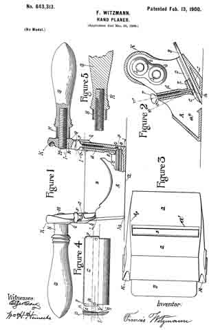
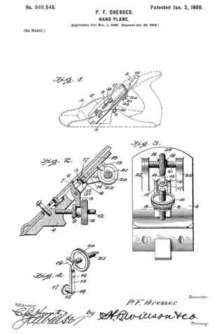
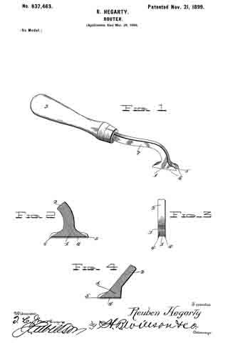
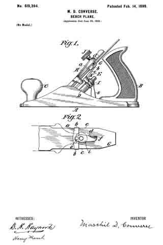
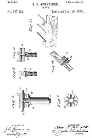
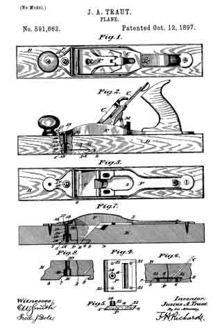
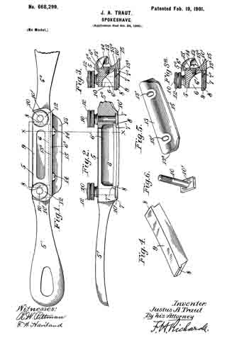
In the accompanying drawings, Figure 1 is a plan view of my improved spokeshave, part of one of the handles being broken away. Fig. 2 is a side elevation, partially in section. Figs. 3 and 3a are transverse sections on line into of Figs. 1 and 2, showing different adjustments of the guard or throat-gage. Fig. 4 is a perspective view of the knife or cutter. Fig. 5 is a perspective view of the guard, and Fig. 6 is a perspective view of one of the bolts for adjustably securing the knife in position.

Similar characters designate corresponding parts throughout the several views.

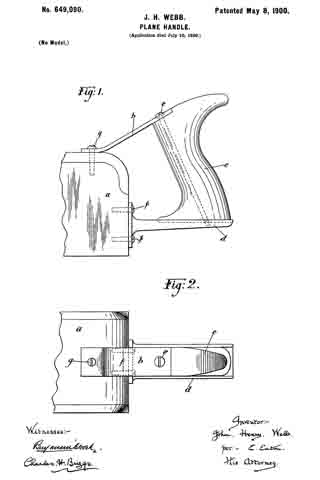
Referring to the drawings, the numeral 5 designates the stock of my improved spoke-shave, having the usual handles 5′ 52 and provided with a chamber 6 (the wall 6′ of which is curved outward for a purpose hereinafter described) and with a forward straight portion 62.

Formed in the stock at each end of the chamber 6 are grooves 7, having rabbeted portions 7′, constituting guideways for the reception of flanges 8 on the ends of a knife or cutter 9, which is preferably of the “razor-blade” type and is slightly curved longitudinally, and fitted in said grooves 7 are the flat oblong heads 10′ of bolts 10, the threaded shanks of which pass through perforations in the stock and carry thumb-nuts 12, by turning which the heads 10′ may either be forced tightly against the flanges 8 of the cutter or released therefrom to permit said cutter to be adjusted, as desired. Cooperating with this cutter is a guard or throat-gage 13, slotted at 13′ for the reception of screws 14, which enter the stock, in virtue of which construction the guard may be adjusted transversely of the cutter to vary the dimensions of the throat in which the shavings enter between said parts.
It will be observed by reference to Figs. 3 and 3a that this guard is provided with a plane back 132, which terminates in a straight edge 133, and when this straight edge is blunted or otherwise injured by wear, as frequently happens, it can readily be restored by removing the guard and grinding the flat face 132, after which it can be replaced with said face in engagement with the corresponding flat face 62 of the stock. On its lower or grinding surface the guard is made convex both longitudinally and transversely, as at 15, and can therefore much more readily be applied to rounded surfaces of the work. The face 15, which extends outward from the edge 133, is joined to the back 132 by the curved surface, which at its upper portion becomes nearly or quite parallel to the back, forming a body of convenient thickness in which to locate the slots 13′.

By reference to Figs. 3 and 3a it will be seen that the knife 9 and guard 13 may be so adjusted with relation to each other that the cutting edge of the knife will be brought into line with and almost touch the straight edge of the guard, whereby a very fine shaving may be removed from the work, if desired.
This is especially important when cutting hard wood or across the grain and obviates to a large extent the danger of splitting the wood or of tearing out a splinter therefrom — accidents of frequent occurrence with the old styles of spokeshaves, in which the knife overlaps a beveled edge on the guard.

As is well known, chips or shavings entering the mouth between the guard and knife tend to curl or assume a helical form, and to aid them in this action they are caused to impinge against the curved wall 6’ of the chamber 6 and are by said wall guided and defiected toward the exterior of the stock.

By my improved construction it will be seen that the guard may be so adjusted that the edge of the knife may be brought into line with the straight edge 133 or caused slightly to overlap the same, if desired, thereby enabling the tool to be employed on various kinds of woods, either hard or soft, at pleasure, for, as is obvious, the height of the knife above the guide-surface and also the position of the cutting edge may be regulated with nicety to obtain a throat of the desired width.

As will be observed, the flat oblong heads 10′ of the bolts 10 extend equally on each side of said bolts, and as said heads snugly fill the grooves 7 of the stock the bolts are thus interchangeable and reversible, so that the parts may be disassembled and reassembled regardless of their original positions. Furthermore, the top surfaces of the heads of these bolts and the bearing-surface of the guard or throat-gage are flush with each other, so as to form a smooth working face for the tool.

Preferably the stock and its handles are formed of metal in an integral casting, although the invention is not limited in this respect.

My invention is not limited to the precise details illustrated and described, and modifications may be made in the shape of the parts without departure therefrom.

Having thus described my invention, what I claim is —

1. In a spokeshave, the combination with a chambered stock of a cutter secured in said stock; and a guard or throat-gage cooperating with said cutter and having a working face curved in two directions and a plane back adjacent to the curved surface, said guard being adjustable to bring the working surface of said gage substantially to a position in line with the edge of the cutter.

2. In a spokeshave, the combination, with a stock and its handles, said stock having a chamber with an outwardly-curved wall and also having grooves and guideways at the ends of said chamber, of a longitudinally-curved cutter having flanges fitted in the ways of said stock; bolts having heads in engagement with said flanges; a guard or throat-gage having a straight back portion adjustably secured to the forward wall of the stock, the working surface of said guard or throat-gage projecting from said back portion and being curved both longitudinally and transversely, and said gage being adjustable on the stock to bring its working surface substantially into line with the edge of the cutter, substantially as and for the purpose specified.

JUSTUS A. TRAUT.

Witnesses:
ROBT. N. PECK,
M. G. PORTER.

No. 661,559 – Gage Attachment For Bench-Planes (Millage Mathew Smith) (1900)

[paiddownloads id=”550″]661559


UNITED STATES PATENT OFFICE.

_________________

MILLAGE MATHEW SMITH, OF STOCKDALE, TEXAS.

GAGE ATTACHMENT FOR BENCH-PLANES.

_________________

SPECIFICATION forming part of Letters Patent No. 661,559, dated November 13, 1900.
Application filed June 16, 1900. Serial No. 20,552. (No model.)

_________________

To all whom it may concern:

Be i t known that I, MILLAGE MATHEW SMITH, a citizen of the United States, residing at Stockdale, in the county of Wilson and State of Texas, haveinvented a new and useful Gage Attachment for Planes, of which the following is a specification.

The invention relates to improvements in gage attachments for planes.

The object of the present invention is to improve the construction of gages for planes and to provide a simple, inexpensive, and efficient device adapted to he readily applied to the stock of a plane and capable of being set at different angles to the face of the same to enable the edge or face of a board or piece to be accurately planed at the desired angle.

The invention consists in the construction and novel combination and arrangement of parts hereinafter fully described, illustrated in the accompanying drawings, and pointed out in the claims hereto appended.

ln the drawings, Figure 1 is a perspective view of a plane provided with a gage attachment constructed in accordance with this invention. Fig. 2 is a transverse sectional view of the same, the plane being shown in elevation. Fig. 3 is a detail perspective view of the attachment, illustrating the manner of journaling the gage-plate on the supporting bar or piece.

Like numerals of reference designate corresponding parts in all the figures of the drawings.

1 designates a curved supporting har or piece arranged at one side of a plane 2 and extending downward and outward from the stock thereof and provided at its ends with clamps 3, consisting of upper perforated ears 4 and lower jaws 5, which are extended and provided with bearings 6 for the reception of journals or pintles 7 of a gage-plate 8. The clamps are adapted to engage the front and rear portions of the stock of the plane at one side thereof, and the upper perforated ears are threaded for the reception of screws 9, which are adapted to clamp the upper face of the stock of the plane at the inner face of the adjacent side or flange thereof, whereby the attachment is secureiy fastened to the stock.

The gage-plate 8, which is adapted to be arranged at different angles to the lower face of the plane to form a guide, is provided at its ends with the pintles 7, which are extended longitudinally from it and which are retained in the said bearings 6 by the stock when the attachment is clamped thereon, and they permit the gage-plate to swing inward and outward to and from the curved supporting piece or bar, which is extended outward and downward beyond the side of the plane, as clearly illustrated in Fig. 2.

The adjustment of the gage-plate is effected by means of a screw 10, pivoted to the said gage-plate at the outer face thereof and extending through an opening 11 of an ear 12, which is located centrally of the supporting bar or piece and which extends upward therefrom. The inner end or head of the screw is provided with a perforation for the reception of a pivot 13, which passes through a pair of perforated ears 14, extending outward from the center of the gage-plate. The adjusting-screw receives inner and outer nuts 15 and 16, located at opposite sides of the projecting portion or ear 12 of the supporting-piece and adapted to be adjusted to move the gage-plate inward and outward and capable of clamping the said ear 12, whereby the gage-plate is securely held at any adjustment. The supporting bar or piece 1 is provided with an upwardly-extending guide 17, located at a point between the adjusting device and one end of the supporting bar or piece and receiving a graduated bar or arm 18, and the latter is pivoted at its inner end between a pair of ears or lugs 19. The ears or lugs 19, which extend outward from the gage-plate and which are preferably formed integral with the same, are perforated for the reception of the pivot 20 of the graduated arm or bar. The graduated arm or bar will enable the gage-plate to be accurately set at the desired angle.

It will be seen that the device is exceedingly simple and inexpensive in construction, that it is adapted to be readily applied to a plane, and that it is capable of being readiiy set at the desired angle for enabling an edge or a face of a board to be accurately planed.

It will also be apparent that the gage-plate is detachably mounted on the supporting bar or piece and that the clamps which engage the stock of the plane and which secure the attachment to the same also operate to retain the journals or pintles of the gage-plate in the bearings of the supporting bar or piece.

What is claimed is —

1. In a device of the class described, the combination with a plane, of a gage-plate provided with pintles or journals, a supporting bar or piece having clamps for engaging the plane and provided in their engaging faces with open bearings receiving the journals or pintles of the gage-plate, said plane fitting over the open bearings and retaining the pintles or journals therein, and an ajusting device connecting the gage-plate with the supporting bar or piece, substantially as described.

2. In a device of the class described, the combination with a plane, of a gage-plate provided with pintles or pivots, a supporting bar or piece provided with clamps composed of lower jaws fitting against the plane and provided with open bearings receiving the pivots or pintles, the plane being arranged over the open bearings, whereby the gage-plate is removably secured to the supporting bar or piece by the engagement of the clamps with the plane, and clam ping-screws located above the said jaws and cooperating with the same, and an adjusting device connecting the gage-plate and the supporting-piece, substantially as described.

3. A gage attachment comprising a supporting bar or piece provided with clamps, a hinged gage-plate, an adjusting-screw pivoted at its inner end to the gage-plate and extending outward through an opening of the supporting bar or piece, nuts mounted on the adjusting-screw and located at the inner and outer sides of the supporting bar or piece, and a graduated bar or arm extending from the gage-plate and passing through a guide of the supporting bar or piece and arranged approximately parallel with the adjusting-screw, substantially as described.

In testimony that I claim the foregoing as my own I have hereto affixed my signature in the presence of two witnesses.

MILLAGE MATHEW SMITH.

Witnesses:
M. S. McGEE,
W. W. YOUNG.

No. 661,010 – Plane (Maschil D. Converse) (1900)

[paiddownloads id=”549″]661010


UNITED STATES PATENT OFFICE.

_________________

MASCHIL D. CONVERSE, OF NEW YORK, N. Y.,
ASSIGNOR TO JOHN J. TOWER, OF SAME PLACE.

PLANE.

_________________

SPECIFICATION forming part of Letters Patent No. 661,010, dated October 30, 1900.
Application filed March 19, 1900. Serial No. 9,276. (No model.)

_________________

To all whom it may concern:

Be it known that I, MASCHIL D. CONVERSE, a citizen of the United States, residing in the city of New York, borough of Manhattan, county of New York, and State of New York, have invented certain new and useful Improvements in Planes, of which the following is a specification.

My invention relates to planes, and more particularly to adjustment mechanisms for the bits or irons thereof.

In planes constructed with clamp-plates and cramp-screws for securing the bit, more especially in those in which the end of the cramp-screw engages the surface of the bit, of which Letters Patent No. 619,394 is an example, it has been found that the point or end of the cramp-screw so indents and mars the surface of the bit that when it is desired to loosen the latter for adjustment the marred surface frequently interferes by either requiring the said cramp-screw to be so much loosened (to free the point or end of the indentations) that efforts to adjust the bit in one direction (either longitudinally or laterally) will cause the other adjustment to be lost or when retightening the cramp-screw its end will slip back again into the indentation or marrings on the bit’s surface, so that the desired adjustment is not with facility and certainty attained.

The objects of my present invention are not only to overcome these difficulties, but to provide a lateral adjustment mechanism which shall be adapted for use also in convertible planes of the type shown in Letters Patent No. 620,226 or analogous ones in which clamp-plates and cramp-screws essentially of the same character as hereinbefore referred to are employed, but in which the end of the cramp-screw instead of engaging the surface of the bit engages a slide or a socket in a slide, and the further object is to provide an inexpensive, simple, and efficient lateral adjustment device that may be expeditiously operated.

To these ends my invention consists in the several particulars of construction, arrangement, and combination of parts severally and more particularly hereinafter pointed out and claimed.

In the drawings, Figure 1 is a side elevation, partly sectional longitudinally, showing my invention as applied in planes of the herein-above first-mentioned type. Fig. 2 is a nether side view of the plane bit or iron, clamp-plate, and my invention removed from the stock, further showing the application and construction of certain parts thereof. Fig. 3 is a side elevation, partly sectional longitudinally, of the hereinabove second-mentioned type, showing the application of my invention to the same. Fig. 4 is a side elevation, partly sectional longitudinally, of one modiiied construction of my invention, sometimes desirable in applying it to this second-mentioned type of planes; and Fig. 5 is a side elevation, partly sectional longitudinally, showing a further-modified application of my invention to this type of planes. These several figures will now be more fully described in detail.

Like letters and the same primed indicate corresponding parts throughout the respective figures.

A in Fig. 1 is the stock of a plane of the hereinabove first-mentioned type, having the usual handle B and knob C and provided with a post D, centrally upon which is mounted obliquely a longitudinally-movable plate E, forming the bed for the bit G, above which is another plate H, also longitudinally movable, which latter I construct with an arch a (said arch being one feature of my present invention) and provide with a cramp-screw J, which passes from the upper side through the outer portion at substantially right angles to its longitudinal plane.

I is a worm-screw (provided with a lever l and pivoted to the post D) to engage a rack K on the under side of the nether clamp-plate or bed E, making a known device for longitudinal adjustment of the bit.

L in Figs. 1 and 2 is a longitudinal slot in the bit having equal dimensions transversely throughout its extent. M in the same figures is a concave-convex thumb-wheel, preferably gnarled or milled on its extreme upturned periphery, having a hole through its axis for reception of the reduced portion or end of the cramp-screw (which latter is made with a shoulder N, as in Figs. 1, 3, and 5) or for the reception of the journal e, as in Fig. 4. This thumb-wheel is provided with an eccentric O, (which I prefer to be integral,) extending from the convex side to enter the slot L and engage the lateral parallel walls thereof. The diameter of this eccentric should be so nearly equal the transverse measurement of the slot L as barely to slide freely therein. The surface immediately surrounding the eccentric radially on the convex side of the thumb-wheel at P, I level or flatten in order that the same may have a considerable area for engagement with the upper side of the plane-bit G by overhanging the lateral margins of the slot L. The arch ct of the clamp-plate H is for the accommodation of the upturned periphery of the thumb-wheel, which latter is so made in order that it may be accessible to the thumb and finger of the operator.

At Q it will be seen that the hole in the axis of the thumb-wheel on the convex side is countersunk and that a portion of the reduced pivot or pivot end is upset at b, so as to prevent the said thumb-wheel from becoming separated from the clamp-plate H when the bit is being removed.

Those skilled in the art will now see that in the operation of my invention the upturned periphery of the thumb-wheel gives convenient access (as before stated) for its manipulation by the thumb and finger of the operator, a construction for the thumb-wheel made possible when placed below the clamp-plate H by the arch a of the latter, that turning the thumb-wheel to either the right or left will accomplish lateral adjustment of the bit, and that the overhanging radially-extended flattened surface of the convex side of the thumb-wheel at P offers an area of sufficient extent to prevent indentation or marring of the surface of the bit, which it engages when the cramp-screw J is tightened, and because the point or end of the cramp-screw is not employed to engage the bit, but its pressure is communicated to the latter by means of the shoulder N, through the thumb-wheel, the under or convex side of which latter bears upon and binds the bit, except in the modification shown by Fig. 4, where the journal or pivot of the thumb-wheel and eccentric is independent of the cramp-screw and is not axially coincident therewith, which cramp-screw, however, in such case does not engage the surface of the bit, but engages a slide or a socket in a slide, as before mentioned, while in the modification shown by Fig. 5 a stud S is fixed in the clamp-plate to engage the socket in the slide (but without pressure on the bottom of the socket) instead of the cramp-screw. The advantages of the device of an arched clamp-plate H, with a thumb-wheel of the form described, will also be readily seen by such both on account of great economy of manufacture (since they severally may be cast in integral parts) and greater efficiency and convenience in operation.

I do not herein claim, broadly, the application of a lateral bit-adjustment mechanism to have its fulcrum coincident to the axis of the cramp-screw, such having been claimed and allowed to me in Letters Patent No. 619,394, dated February 14, 1899, nor do I wish to limit myself in my present invention to a combination with the cramp-screw as a pivotal axis therefor, since manifestly the improved form and construction of the leading features of my present invention adapt it to be employed on an independent pivot similarly to that shown in Fig. 4.

Having described my invention, what I do claim as new, and desire to secure by Letters Patent, is —

1. In a plane a lateral bit-adjustment mechanism comprising an arched clamp-plate carrying a pivot and cramp-screw, a concavo-convex thumb-wheel revolubly mounted on said pivot, provided with an eccentric on its convex side and a radially-flattened surface thereon adjacent to said eccentric, in combination with a longitudinally-slotted bit.

2. In a plane a lateral bit-adjustment mechanism comprising an arched clamp-plate carrying a shouldered pivot and cramp-screw, a concavo-convex thumb-wheel revolubly mounted on said pivot, provided with an eccentric on its convex side and a radially-flattened surface thereon adjacent to said eccentric, in combination with a longitudinally-slotted bit.

3. In a plane a lateral bit-adjustment mechanism comprising an arched clamp-plate carrying a pivot and cramp-screw, a concave-convex thumb-wheel revolubly mounted on said pivot, provided with an eccentric on its convex side and a radially-flattened surface thereon adjacent to said eccentric and means for preventing the said thumb-wheel from becoming accidentally detached from said clamp-plate, in combination with a longitudinally-slotted bit.

In testimony whereof I afiix my signature in presence of two witnesses.

MASCHIL D. CONVERSE.

Witnesses:
H. S. WELCH,
FRANK A. JONES.

No. 659,287 – Bench-Plane (Edward O. Carvin) (1900)

[paiddownloads id=”548″]659287


UNITED STATES PATENT OFFICE.

_________________

EDWARD O. CARVIN, OF VALLEY SPRINGS, CALIFORNIA,
ASSIGNOR OF ONE-HALF TO T. J. FRENCH, OF SAME PLACE.

BENCH-PLANE.

_________________

SPECIFICATION forming part of Letters Patent No. 659,287, dated October 9, 1900.
Application filed June 14, 1900. Serial No. 20,364. (No model.)

_________________

To all whom it may concern:

Be it known that I, EDWARD O. CARVIN, a citizen of the United States, residing at Valley Springs, in the county of Calaveras and State of California, have invented certain new and useful Improvements in Planes; and I do hereby declare the following to be a full, clear, and exact description of the invention, such as will enable others skilled in the art to which it appertains to make and use the same.

This invention relates to carpenters’ planes, and more particularly to the means whereby the handle is susceptible of adjustment to a variety of positions to meet diiferent conditions to facilitate the work and secure ease and comfort to the workman.

The improvement consists of the novel features and the details of construction, which hereinafter will be more fully set forth, and finally pointed out in the appended claims.

In the drawings, Figure 1 is a side elevation of a plane constructed in accordance with and embodying the essential features of the invention. Fig. 2 is a central longitudinal section thereof. Fig. 3 is a top plan view, parts being broken away. Fig. 4 is a detail view showing different mountings for the handle. Fig. 5 is an end view of the construction shown in Fig. 4. Fig. 6 is a detail view showing different means for securing the handle in an adjusted position.

Corresponding and like parts are referred to in the following description and indicated in all the views of the drawings by the same reference characters.

The body 1 of the plane may be of any size and pattern, according to the style of plane, and is provided with a throat 2, adapted to deliver the shavings at one side of the plane, said throat extending transversely of the body and flaring from one side thereof to the other. The rear or heel portion of the body is reduced in depth to enable the handle 3 to be as low down as possible, and the heel portion 4 is reinforced by a horizontal plate 5, secured thereto and provided at its ends with vertical extensions 6 and 7, the latter projecting above and below the plate 5, as shown, the upper extension receiving the rear end of the handle-support 8 and the lower extension overlapping the rear end of the heel portion 4. The parts 5, 6, and 7 are of integral formation and are secured to the parts of the body in any substantial manner. The bit 9 is secured to the lower face of the body 1 in the rear of the throat 2 and is adjustable longitudinally to compensate for wear incident to sharpening. Clamp-screws 10 are let into the body 1 and their heads fit countersunk portions of longitudinal slots 11, formed in the bit, so as not to project beyond the lower face thereof. After the bit has been properly positioned it is secured by tightening the clamp-screws 10, and in order to prevent possible slipping of the bit the latter is formed upon its top side or the face adapted to lie adjacent to the lower side of the body 1 with transverse serrations or Iine teeth 12, which bite into the face of the body and positively hold the bit in the adjusted position after the clamp-screws have been properly tightened. The bit 9 protects the lower face of the body 1 and by being disposed in the manner set forth operates by a more direct cut, whereby knots and timber are adapted to be readily cut across grain.

In order to regulate the depth of out or thickness of shaving, a gage-plate 13 is located in advance of the throat 2 and is vertically adjustable, any suitable means being employed to effect this result, and, as shown, companion set-screws let are threaded into the body of the plane and make swivel connection at their lower ends with bosses provided upon the top side of the gage-plate 13, said set-screws being adapted to be turned by means of thumb-buttons 15 at their upper ends. Jam-nuts 16 are fitted to the set-screws 14 to hold the latter in the required position. By turning the set-screws either to the right or to the left the gage-plate can be lowered or raised, according to the desired thickness of shaving to be cut.

The handle-support 8 is a rod or bar centrally disposed with reference to the body 1 and secured at its ends to the vertical extensions of the plate 5. The handle 3 is adjustable on the support 8, so as to be brought nearer to the cutting edge of the bit or farther away therefrom, according to the nature of the work and the convenience to the user. The handle, in addition to its longitudinal adjustment with reference to the plane, can be turned to any desired angular position either to the rightor to the left, thereby enabling the plane to be used in angles and close quarters, where it would be inconvenient to grasp the handle and manipulate the plane if said handle occupied a vertical position. Any means may be employed for securing the handle in the required position, and, as shown in Figs. 1, 2, and 3, a pair of nuts 17 is mounted upon the rod 3, which latter is screw-threaded throughout its length, the handle 3 being clamped between the nuts of the pair.

In the construction shown in Figs 4 and 5 the rod or bar 8a is formed in a side with a series of openings 18, and the handle 3 is provided with a spring-actuated pin 19 to enter any one of the openings 18 and hold the said handle in an adjusted position, the pin 19 being operated by means of a thumb-latch 20, pivoted to the offset portion of the handle. This support 8a is mounted in the vertical extensions of the plate 5 so as to turn and is provided at its rear end with a spring-arm 21, provided with a stud 22 to enter one of a series of openings 23, formed in the rear face of the vertical extension 7, whereby the handle is positively secured when turned either to the right or to the left from a vertical position. The construction is such as to admit of the body 1 being formed of wood, the plate 13 and the bit 9 forming a metal surface for the lower side thereof to protect it from wear and injury. The depression of the bit enables it to operate by a more direct cut, whereby it will pass more easily through knotty wood and across grain without disturbing the fibrous structure of the material to such an extent as to leave a rough surface commonly experienced when dressing knotty timber by planes of ordinary construction. In the event of the body 1 being of metal or other material the plate 13 and the bit 9 form a facing therefor.

Fig. 6 shows the handle 3 mounted upon a smooth rod 8b and provided with a clamp device consisting of rod 24, having its inner end portion threaded to coact with a nut 25, let into the handle and having its outer end bent, as at 26, to form a grip for turning the rod to release or secure the handle.

Having thus described the invention, what is claimed as new is —

1. In combination with a carpenter’s plane, a handle adjustable lengthwise of the plane and to any angular position, and means for securing the handle in an adjusted position, substantially as set forth.

2. A carpenter’s plane having its rear portion rednced upon its top side for a short distance from its rear end, a support disposed parallel of the plane and located above the heel thereof, and a handle adjustably mounted upon the said support, substantially as specified.

3. In combination with a carpenter’s plane, a support mounted so as to be turned about its axis, means for turning said support and securing it in an adjusted position, and a handle adjustable on the said support, substantially as specified.

In testimony whereof I affix my signature in presence of two witnesses.

EDWARD O. CARVIN. [L. S.]

Witnesses:
JAMES B. LUDDY,
F. J. SOLINSKY.

No. 649,090 – Plane-Handle (John Henry Webb) (1900)

No. 649,090 – Plane-Handle (John Henry Webb) (1900)

[paiddownloads id=”547″]649090


UNITED STATES PATENT OFFICE.

_________________

JOHN HENRY WEBB, OF CARDIFF, ENGLAND.

PLANE-HANDLE.

_________________

SPECIFICATION forming part of Letters Patent No. 649,090, dated May 8, 1900.
Application filed July 10, 1899. Serial No. 723,413. (No model.)

_________________

To all whom it may concern:

Be it known that I, JOHN HENRY WEBB, of Riverside, Cardiff, England, have invented certain new and useful Improvements in or Relating to Handles for Planes and other Tools, of which the following is a full, clear, and exact description.

In carrying out my invention I provide a handle of suitable material which is attached to the plane in any convenient position by means of grooves or such like. I provide strengthening brackets or supports. In ordinary plane-handles these are cut from wood in the solid and are mortised into the plane-block; but by my invention this handle may be attached to the block without cutting the block, it being merely necessary to secure the handle to the supports which are attached to the plane-block.

For purposes of illustration I will now refer to the annexed drawings, in which —

Figure 1 is a side elevation showing my invention applied to a plane, and Fig. 2 a plan view of same.

a, is a plane-block to which the brackets b and d are attached by means of the screws g and f, the bottom bracket d being recessed, as indicated by the dotted lines. The handle c is secured between the brackets b and d by means of the screw e, which passes through the top bracket b, through the handle c, and is then screwed into the bracket d, thus securing the handle c in position.

Having thus described my invention, what I claim, and desire to secure by Letters Patent, is —

In means for attaching handles to plane-blocks, in combination, two brackets secured by means of screws to the plane-block, one upon the end thereof and the other upon the adjacent top of the plane-block; a handle of suitable material adapted to engage between said brackets, a screw passing through top bracket and handle and engaging in the bottom bracket for the purpose of securing the handle in position, a recess in said bottom bracket for the reception of said handle, substantially as described and illustrated herein and for the purpose set forth.

In testimony that I claim the foregoing I have hereunto set my hand this lst day of April, 1899.

JOHN HENRY WEBB.

Witnesses:
JAMES SLEVIN,
WILLIAM JOHN WEEKS.

No. 646,262 – Wood-Plane (Herbert M. Coe) (1900)

[paiddownloads id=”546″]646262


UNITED STATES PATENT OFFICE.

_________________

HERBERT M. COE, OF PHOENIX, ARIZONA TERRITORY.

WOOD-PLANE.

_________________

SPECIFICATION forming part of Letters Patent No. 646,262, dated March 27, 1900.
Application filed May 2, 1899. Serial No. 715,322. (No model.)

_________________

To all whom it may concern:

Be it known that I, HERBERT M. COE, of Phoenix, in the county of Maricopa and Territory of Arizona, have invented a new and Improved Wood-Plane, of which the following is a full, clear, and exact description.

This invention relates to improvements in planes or spoke-shaves adapted for planing or shaving around circular bodies; and the object is to provide a tool of this character of simple yet strong construction that may be quickly adjusted to operate on flat surfaces or on curved surfaces of any radius.

I will describe a wood-plane embodying my invention and then point out the novel features in the appended claim.

Reference is to be had to the accompanying drawings, forming a part of this specification, in which similar characters of reference indicate corresponding parts in all the figures.

Figure 1 is a top plan view of a wood-plane embodying my invention. Fig. 2 is a section on the line 2 2 of Fig. 1, and Fig. 3 is a similar section of a slightly-modified construction.

Referring to the drawings, 1 designates a frame of suitable material — such, for instance, as metal — the side portions of which are curved upward and rearward, and at the front these side portions are connected by a cross-bar 2, and inward of the cross-bar is a cross-block 3. The space between the block 3 and the inner edge or side of the cross-bar 2 forms the throat of the tool. The frame is provided with oppositely-extended handles 4, so that the tool may be used as a spoke-shave. Extended rearward from and underneath the block 3 is a bed-plate 5, which bed-plate extends entirely across the frame or that portion of the frame occupied by the block 3, and it is made of spring material. In Fig. 2 I have shown it secured to the tool by having a portion 6 extended between the upper surface of the block 3 and the cutting-bit 7, which is held in place by the usual plate 8 and screw 9. In Fig. 3, however, I have shown the plate 5 as having its forward edge riveted to the forward end of the block 3.

Pivotally connected to the rear edge of the base-plate 5 is a curved arm 10, which passes through an opening in a lug 11 on the frame 1 and having a clamping-screw 12. In operation the tool may be employed for operating upon flat surfaces, and in such case the bed-plate will be arranged as indicated in full lines in Fig. 2. When it is to be used upon cylindrical or similar curved surfaces, the bed-plate 5 may be deflected to any desired degree to conform it to the shape or size of the article operated upon by moving the arm 10 through the lug 11 and clamping it by the screw 12.

While I have indicated in dotted lines in Fig. 2 a position for the plate 5 when the tool is to be used upon the exterior of a cylindrical body, it is obvious that the plate may be deflected in the opposite direction, so that the tool may be used on the inner side of a cylinder or the like.

Having thus fully described my invention, I claim as new and desire to secure by Letters Patent —

A wood-plane, comprising a frame, a cross-block in said frame upon which the plane-bit is designed to be secured, a flexible bed-plate extended rearward from said cross-block and having at its front end a portion extended upward between the block and bit and secured between the same, a curved arm having pivotal connection with the rear end of the plate, a perforated lug on the frame through which said arm may move, and a clamping-screw in the lug, substantially as specified.

HERBERT M. COE.

Witnesses:
J. C. DAVIS,
C. H. DAVIS.

No. 645,220 – Bench-Plane (Justus A. Traut) (1900)

[paiddownloads id=”545″]645220


UNITED STATES PATENT OFFICE.

_________________

JUSTUS A. TRAUT, OF NEW BRITAIN , CONNECTICUT.

BENCH-PLANE.

_________________

SPECIFICATION forming part of Letters Patent No. 645,220, dated March 13, 1900.
Application filed December 10, 1897. Serial No. 661,391. (No model.)

_________________

To all whom it may concern:

Be it known that I, JUSTUS A. TRAUT, a citizen of the United States, residing in New Britain, in the county of Hartford and State of Connecticut, have invented certain new and useful Improvements in Planes, of which the following is a specification.

This invention relates to planes, and especially to knife-adjusting means therefor; and it has for its main object the provision of an improved tool of this type in which the knife can be set quickly in an adjusted position and held firmly in place without the use of adjusting-levers, the construction being such that all of the parts can be separated and assembled with great rapidity and precision.

My present improvements are designed more particularly for use in connection with planes of that type in which the knife or plane-bit is disposed at a comparatively-small angle with respect to the sole of the plane, thereby leaving but a small space at the rear end or heel of the plane for the knife adjusting and holding devices, and it is of the utmost importance in tools of this kind to provide holding and adjusting means which may be assembled and disassembled readily and operated a minimum distance for the purpose of effecting the proper adjustment of the plane-knife. It is essential, of course, that all of these parts should be so organized that the knife will be held firmly in place when set in any adjusted position, or else the adjustment of the bit might be changed and the proper operation of the tool prevented.

In the plane illustrated in the drawings of this application I have illustrated devices for obtaining two different adjustments of the plane knife or bit — one a rough adjustment, by means of which the knife may be brought quickly approximately to its proper position, and a fine adjustment, which will be effected, preferably, by means of a suitable adjusting-screw.

The device which I employ for obtaining the fine adjustment of the plane-bit constitutes one of the main features of this invention, and I may employ for this purpose an adjusting-screw having two diderent threads thereon, one of which coacts with a suitable member of the plane-bit and the other with the knife or its carrier. In this instance the knife is supported on a slide which will have a supporting-face oblique to the sole of the plane and will be shifted toward and from such sole by means of an adjusting-screw of the kind just described. Preferably the adjusting-screw will have two similar threads of different pitch, one of which will engage a fixed member of the body of the plane and the other of which will engage the slide, the parts being so organized that when the screw is turned it will move in the same direction through both the slide and the supporting member of the plane-bit and will at the same time cause the slide to be shifted toward and from such supporting member in accordance with the direction of movement of the screw.

The screw which I employ will be of two diameters in order that the smaller diameter thereof, which is at the point, may admit of the insertion of the reduced part through a proper threaded opening or fixed nut in the plane-bit; but the threads of the portion of the screw which is of larger diameter engage the corresponding internal threads of the member or fixed nut on the body of the plane. Hence it will be evident that in assembling the parts the reduced end of the screw may be passed through the threaded member of the plane-body and the point of the screw then inserted in the proper threaded opening or fixed nut of the slide, whereupon the screw may be turned into the two parts simultaneously by the turning of two similar threads of different pitch in the same direction, and thus draw the slide toward the supporting member of the plane-body while the screw is advancing through the threaded member or fixed nut of the latter. It will be noticed that this movement of the slide toward the fixed member on the body is due to the fact that the thread at the forward end of the screw is of quicker pitch than that near the head of the screw.

For the purpose of effecting the coarse adjustment of the plane-knife said knife and its support will have coacting holding members, one of the parts having a single holding member and the other a series, although each of the members of said series is adapted to engage said single holding member, so as to lock the plane-knife roughly in any desired position with respect to the throat of the plane. Usually the knife-support, which in this case will be the slide, will have a stop or rib projecting therefrom and adapted to enter any one of a longitudinal series of recesses in the plane-bit, these recesses being preferably in the form of parallel transverse grooves in the under side of the knife. It will be clear that these coacting holding means will permit a rough adjustment of the knife approximately in the desired position and that the fine adjustment may be effected afterward by means of the screw. Moreover, when the knife has such a row of recesses or grooves therein as that just described it will be apparent that the knife may be used in connection with planes of several different sizes, which is a matter of considerable importance.

In the drawings accompanying and forming part of this specification, Figure 1 is a sectional side elevation of a plane constructed in accordance with my present improvements. Fig. 2 is a transverse section of the plane-body and the slide, the section being taken in the line 2 2, Fig. 1, looking toward the heel of the plane. Fig. 3 is a perspective view of the knife supporting and adjusting slide, and Fig. 4 is a perspective view of the rear end or heel of the plane-body and illustrates the supporting member or guide on which the knife-adjusting slide is mounted.

Similar characters designate like parts in all the figures of the drawings.

As to many of the features thereof the body of the plane illustrated herein is similar to plane-bodies as ordinarily constructed. In this case the plane-body (designated in a general way by B) embodies as its essential features a flat base or sole s, side walls 2 2, and a support or guide, such as g, on which the slide will be carried. This guide may be of any suitable construction and is substantially U-shaped in this case in horizontal section and has a pair of oblique supporting-faces 3 3, on which the slide may move. At the inner side of the two side walls 4 4 of the guide I have illustrated a pair of channels or grooves 5 5, forming, with the oblique faces 3 3,ways for locating and guiding the slide.

As before stated, the knife or plane bit is intended to be supported on a slide shiftable by means of a feed-screw in order to obtain the fine adjustment of the knife, and this slide is indicated by S. It may be of any suitable construction, but in this case will have a pair of channels or grooves 6 6 in the under side of the main or fiat portion 7 thereof, these grooves being parallel to each other and so disposed as to cooperate with the guide-faces 3 3 and the grooves 5 5, as will be evident by referring to Fig. 2. It will be clear that this slide moves on the ways of the guide g toward and from the sole of the plane in a path oblique to such sole, this method of mounting the slide being well understood.

For the purpose of shifting the slide in the manner described I have illustrated at f 2 feed-screw of the type which has been hereinbefore referred to, the body portion of this screw being of two diameters and one portion having right-hand threads of one pitch and the other having corresponding threads of a different pitch. In this case it will be clear that the threads 10 are of a relatively-slow pitch, while the threads 12 are of somewhat-quicker pitch, and hence will be capable of shifting the slide with which they codperate so as to move said slide toward and from the back wall 13 of the guide g, in which back wall the feed-screw is mounted so as to lie obliquely to the sole s. The wall 13 of the guide is bored and screw-threaded to correspond with the threads 10 and form a fixed nut, in which the larger portion of the screw may work, while the slide S will have in this case a fixed nut in the form of a depending lug 14, internally screw-threaded to cooperate with the threads 12 of the point of the screw f. When the parts are properly fitted, the slide S may be shifted longitudinally of the slide-supporting faces of the guide, but will be held down and will be prevented from rising by reason of its connection with the screw f, which is braced firmly, and will be supported by the guide in such a manner that it will have no movement except in the direction of its length.

In assembling the parts the feed-screw, which will usually have a milled head, such as 15, of relatively-large diameter for the purpose of turning the screw freely, will be inserted through the opening 13′ until the threads 10 come into engagement with the threads of such opening, and the point of the screw will then be inserted into the opening 14′ in the fixed nut of the slide from the rear side thereof when the slide is in its extreme forward position on the ways of the guide. When the screw is turned to the right, the threads 10 will turn forward and the feed-screw will gradually pass through the opening 13’ toward the throat of the plane, and at the same time the threads 12 will turn forward in the fixed lug 14 of the slide and by reason of their quicker pitch will cause the slide to shift toward the wall 13. It will be seen that by employing a feed-screw of this type the assembling of the slide, the feed-screw, and the plane-body will be effected with a minimum movement of the slide on the guide g, since the screw advances into both of the fixed nuts in the same direction and does not, as is the case with a right and left hand screw, have to be inserted into one side of one nut and into the other side of the other nut. Hence the slide can be put in place approximately in its proper position, and its screw then turned into both of the fixed nuts a relatively-slight distance to position properly the knife to be supported and adjusted by the slide. This form of feed-screw and cooperating fixed nuts and the manner of assembling the parts described are of distinct utility, especially in those planes of the type illustrated herein having their knives set at a very slight angle to the sole, leaving but a small amount of available space between the rear end of the knife and the heel of the plane. By employing the devices shown herein this space is utilized to the best advantage, and all of the parts are of ample size and strength to operate properly and hold the bit firmly.

The plane knife or bit is indicated by k and may be of any suitably type. This knife and the slide S are intended to have coacting holding members, such as those hereinbefore described, for effecting the coarse adjustment of the bit. The holding member of the slide is indicated at 16 and is in the form of a stop or rib rising from a central wall or larger rib 17 of the slide S, the face 17′ of this wall or rib constituting the supporting-face on which the upper or rear end of the knife is carried. The other holding members, which cooperate with the stop or rib 16, are carried by the knife k and in the construction shown are in the form of a series of recesses or parallel transverse grooves 18 in the under side of said knife, these grooves forming between them transverse stops or ribs substantially similar to the ribs 16, the groove 18 being just large enough to receive the rib 16 and leave no extra space.

It will be clear that after the slide and its feed-screw are in place on the plane-body a rough adjustment of the knife may be obtained by simply placing the proper groove 18 over the stop 16 and placing the knife down upon the supporting-face 17′ of the guide. After this coarse adjustment is obtained the knife should of course be clamped firmly to the slide S, after which the adjusting-screw f may be turned to effect the fine adjustment of the knife.

Any suitable clamping means may be employed for holding the knife in place. That shown herein is indicated in a general way only and will preferably be of the type fully shown and described in Letters Patent No. 591,663, dated October 12, 1897. This main clamping device is in the form of a cam-lever (indicated by 20) carried by a knife clamp or plate c of ordinary construction, this latter being mounted at its forward end on a fixed part, such as 22, of the plane-body by means of a screw-and-slot connection, such as 23, of the usual type. This screw 23 serves to prevent sidewise movement of the forward end of the knife, while the cam-lever by raising the rear end of the knife-clamp c wedges the rear end of the clamp and the knife together and also forces the forward end of the clamp against the knife near the throat of the plane to hold the parts firmly in place.

After the rough adjustment of the bit has been obtained and the latter has been clamped in place by the means just described the screw f will be turned to obtain the iine adjustment of the knife, and it will be noticed that during this last-mentioned adjustment the part which operates directly to effect such adjustment of the bit is not only movable, but supports the knife directly and guides it, thus rendering unnecessary the employment of other or separate means for such purpose.

Having described my invention, I claim —

1. In a plane, the combination, with a plane-body comprising a sole and a pair of side walls, said sole having rigid with the inner face thereof a U -shaped slide-supporting guide the side walls of which extend in parallelism with the body side walls and have their upper edges inclined and recessed to form ways, and connected at their outer ends by an end wall having an internally-threaded opening; a slide mounted on said guide and recessed at its edges to cooperate with said ways, and provided at its under side with an internally-threaded depending lug working intermediate said side walls and on its upper side with a longitudinally-extending centrally-located rib having a transversely-extending rib or projection; a knife adapted to be clamped on said rib and provided with a plurality of transversely-extending recesses for the reception of said transverse rib to locate the knife in position; an adjusting-screw of different diameters working in said guide and slide and having two sets of similar threads of different pitch; and means for clamping the knife in position on said slide.

2. In a plane, the combination, with a plane-body comprising a sole and a pair of side walls, said sole having rigid with the inner face thereof a slide-supporting guide the side walls of which extend in parallelism with the body side walls and have their upper edges inclined, and which walls support at their outer ends a member having an internally-threaded opening; a slide mounted on said guide and provided at its under side with an internally-threaded depending lug working intermediate said side walls and on its upper side with a longitudinally-extending centrally-located rib; a knife adapted to be clamped on said rib, said knife and rib having, one a projection, and the other recesses cooperating with said projection to locate said knife in position; an adjusting-screw of different diameters working in said guide and slide and having two sets of similar threads of diderent pitch; and means for clamping the knife in position on said slide.

JUSTUS A. TRAUT.

Witnesses:
H. S. WALTER,
W. J. WORAM.

No. 644,191 – Carpenter’s Plane (Abraham W. Stauffer) (1900)

[paiddownloads id=”544″]644191


UNITED STATES PATENT OFFICE.

_________________

ABRAHAM W. STAUFFER, OF PHILADELPHIA, PENNSYLVANIA.

CARPENTER’S PLANE.

_________________

SPECIFICATION forming part of Letters Patent No. 644,191, dated February 27, 1900.
Application filed May 6, 1899. Serial No. 715,818. (No model.)

_________________

To all whom it may concern:

Be it known that I, ABRAHAM W. STAUFFER, a citizen of the United States, residing at Philadelphia, in the county of Philadelphia and State of Pennsylvania, have invented a certain new and useful Improvement in Carpenters’ Planes, of which the following is a specification.

My invention relates to a new and useful improvement in carpenters’ planes, and has for its object to provide a simple and effective means for adjusting the blade of the plane either up and down or sidewise and for clamping and holding the blade firmly in position.

With these ends in view this invention consists in the details of construction and combination of elements hereinafter set forth and then specifically designated by the claims.

In order that those skilled in the art to which this invention appertains may understand how to make and use the same, the construction and operation will now be described in detail, referring to the accompanying drawings, forming a part of this specification, in which —

Figure 1 is a side view of the plane having my improvements embodied therein; Fig. 2, a plan view thereof; Fig. 3, an enlarged section of a portion of the stock of the plane, showing my improvements in section and in position; Fig. 4, a detail view of the bed-block removed from the stock and showing the device for adjusting the bit; Fig. 5, a similar view of the back of the bit; Fig. 6, a section at the line y y of Fig. 4; Fig. 7, a detail view of the clamping-bar, and Fig. 8 represents the clamping-screw.

In carrying out my invention as here embodied, A represents the plane-stock, having fitted therein the bed-block B, which is adjustably secured within the throat of the plane by means of suitable screws passing through the slots C and into the stock. The upper surface of the bed-block is recessed, as shown at D, so as to receive the adjusting-lever E, which has a fulcrum extension F, upon which this lever rocks when being manipulated, said extension fitting within the recess G, formed for that purpose. The adjusting-lever has a hole H formed therein, which registers with the elongated hole I, formed in the bed-block, and through these two holes passes the clamping-screw J, the latter being threaded into the clamp-plate K. This plate is adapted to fit upon the upper surface of the bit L when the latter is in position upon the bed-block, forming a cap therefor, and the clamping-screw J passes through the slot M, formed in the bit, the upper end of which slot is enlarged, as at N , in order that the head of the screw may be withdrawn from the bit. A washer O is placed around the screw and bears against the under side of the bit, and a bushing P is interposed between this washer and the head of the screw in order that when the said screw is run into the clamp-plate the washer will be firmly bound against the under side of the bit, while the clamp-plate will be as firmly bound against the upper surface of the bit, thus tightly securing these parts together. When not assembled, the washer lies within the hole H in the adjusting-lever, permitting the latter to swing thereon.

Q is the clamping-bar, slotted at its lower end, as indicated at R, so as to embrace the screw and bushing thereon and be adapted to draw downward upon the head of said screw. This bar has a ridge S thereon, which acts as a fulcrum, bearing against the under side of the bed-block, so that when the outer end of the bar is forced upward, as hereinafter set forth, the lower end will be swung downward, as will be readily understood, thereby drawing with it the clamping-screw, and consequently the clamp-plate and bit. This action will force the bit firmly against the bed-block, thus holding it against any movement while the plane is in use. A plate-spring T is secured to the under side of the clamping-bar, so as to hold the latter in position and yet permit its movements when being operated to bring about the above-named results.

In order that the outer end of the clamping-bar may be drawn upward with sufficient force to accomplish the results aimed at, a thumb-screw U is passed through the slot V, formed in the bar and threaded in the bed-block, as clearly shown in Fig. 3, and, as is obvious, when this screw is run upon the bed-block it will draw the outer end of the bar upward, the purpose of the slot being to permit the withdrawal of the clamping-bar from the stock when it is desired to release the clamping-screw, and thereby permit the removal of the bit and parts carried thereby.

The upper portion of the bed-block is slotted, as shown at W, and through this slot passes a thumb-screw X, its inner end being threaded into the adjusting-lever E, so that when said lever has been swung to the position which properly adjusts the bit it may be there held by properly manipulating this thumb-screw.

While the bit under ordinary conditions will be held in its adjustment by the clamp-plate, the use of the screw X to hold the adjusting-lever will permit said lever also to act as a means for holding the bit in its adjustment, since so long as the adjusting-lever is held against movement the bit cannot have any lengthwise movement on account of the washer O fitting snugly within the hole H.

The means which I provide for the sidewise adjustment of the bit, which enables the cutting edge of the latter to be properly trued up, is as follows: A cross-slide Y is fitted in dovetailed grooves formed in the bed-block and has lips a formed upon its ends, which embrace the bit, and the movements of this slide are controlled by the spiral cam b, which projects into the groove formed in the slide, said cam being pivoted to the bed-block by the screw d. A thumb-lever e is formed with the cam for its manipulation, so that by drawing this lever to one side or the other the slide will be moved crosswise of the bed-block, and thereby swing the bit upon the washer O as the fulcrum, which, as is obvious, will adjust the cutting edge of the bit, and thereby permit the truing up of the same.

From this description it will be seen that effective means are provided for the adjusting of the bit vertically and also for the truing up of the same, as well as providing for firmly clamping the bit in any adjustment, the latter being especially true since the entire under surface of the clamp-plate fits against the bit, while the under surface of the bit fits against the bed-block, so that when the clamp-plate is drawn downward it will firmly hold said bit.

Having thus fully described my invention, what I claim as new and useful is —

1. In combination with a plane of the character described, a bed-block adjustably secured within the stock, an adjusting-lever fitted within a recess formed in the bed-block, an extension formed with the adjusting-lever and fitted within the recess in the stock, said lever having a hole therethrough, a bit having a central slot therein, a clamp-plate adapted to fit upon the upper surface of the bit, a clamping-screw threaded into the plate, a washer surrounding the screw and adapted to bear against the under side of the bit and fit within a hole formed in the adjusting-lever, a bushing also surrounding the screw and bearing against the washer, a clamping-bar fulcrumed against the under side of the bed-block having its lower end slotted to engage the head of the screw, and means — such as a thumb-screw for drawing the upper end of the clamping-bar toward the bed-block whereby the lower end thereof will be caused to draw the screw and the parts carried thereby downward, as and for the purpose set forth.

2. In combination with a plane of the character described, a bed-block adjustably secured within the stock, an adjusting-lever, an extension formed with the adjusting-lever, a bit adjusted thereby, a clamp-plate, a clamping-screw, a washer and bushing surrounding said screw, a clamping-bar and means for operating the same.

In testimony whereof I have hereunto affixed my signature in the presence of two subscribing witnesses.

ABRAHAM W. STAUFFER.

Witnesses:
MARY E. HAMER,
S. S. WILLIAMSON.

No. 643,313 – Hand-Planer (Francis Witzmann) (1900)

[paiddownloads id=”543″]643313


UNITED STATES PATENT OFFICE.

_________________

FRANCIS WITZMANN, OF NEW YORK, N. Y., ASSIGNOR OF ONE-HALF
TO ALEXANDER MONAGHAN, OF NEW ORLEANS, LOUISIANA.

HAND-PLANER.

_________________

SPECIFICATION forming part of Letters Patent No. 643,313, dated February 13, 1900.
Application filed March 25, 1899. Serial No. 710,475. (No model.)

_________________

To all whom it may concern:

Be it known that I, FRANCIS WITZMANN, a citizen of the United States, residing in New York city, borough of Manhattan, State of New York, have invented certain new and useful Improvements in Hand-Planers, of which the following is a specification.

The object of my invention is to provide a planer that shall be capable of planing the heads of barrels, kegs, tubs, and the like, while assuring that the hands of the operator need not come in contact with the chime, and which shall also be capable of planing other surfaces.

The invention consists in the novel details of improvement and the combinations of parts, that will be more fully hereinafter set forth and then pointed out in the claims.

Reference is to be had to the accompanying drawings, forming part hereof, wherein —

Figure 1 is a front view, partly in section, of a hand-planer embodying my invention. Fig. 2 is a vertical cross-section thereof. Fig. 3 is an inverted plan view of the planer. Fig. 4 is a detail and transverse sectional view of a clamp or wedge, and Fig. 5 is a detail sectional view of the handle.

In the accompanying drawings, in which similar letters of reference indicate corresponding parts in the several views, A indicates a frame of suitable construction, and which is shown provided with a bottom plate a, having a slot or opening a’, opposed side walls a2, and upwardly and outwardly inclined back wall J, upon which a blade B is adapted to rest so thatits lower cutting edge will project into or through the opening a’.
(See Fig. 2.)

C is a clamp or wedge that is adapted to bear upon the blade B to hold the latter in the operative position. Means are provided for retaining the clamp C in such position that its lower beveled edge will aline with and lie near the cutting edge of the blade B, and for this purpose I have shown the clamp C as provided with projections or tongues P, that are adapted to pass into grooves D in the walls a2, which grooves are shown parallel with the walls J and the blade B and above the latter, and the lower ends m, of these grooves form abutrnents, against which the ends l of projections or tongues P rest to regulate the distance that the clamp C can be pushed into the frame. The clamp is held in place so as to create a pressure upon the blade B by means of screws F, which mesh in threaded bores c in lugs d, cast on the inner faces of walls a2 and extending upwardly above the clamp C, the lower ends of these bores c opening above said clamp to enable the ends of the screws F to bear upon the clamp. (See Fig. 2.) The lower parts of lugs d are shown reduced to allow greater freedom for the passage of chips. In line with the bores c the clamp C is provided on its upper surface with countersunk recesses k, into which the tapered ends of the screws F fit.

From the foregoing it will be understood that the clamp C is retained in the lower working position by the projections or tongues P, engaging the abutments m, and that the screws F by entering the recesses k keep the clamp from slipping out of place. By forcing the screws F upon the clamp the latter will hold the blade B rigidly in the cutting position, and by slacking back the screws the pressure of the clamp upon the blade will be reduced and the blade can be readily adjusted more or less into the cutting position to make the desired depth of cut. It will also be seen that when the blade is withdrawn from the frame the clamp will still remain in the working position. As shown, the winged ends of screws F project above the upper edges of the sides a2 of the frame A in position to be readily operated, and the lower edge of the clamp can be seen through the top opening of the frame, whereby as the clamp remains in position it acts as a sight-guide in adjusting the cutting edge of the blade B to a true position transversely of the frame.

The side walls a2 of the frame A are carried high up from the lower wall a, and there is an open space between said walls, as shown in Fig. 1, and to these walls handles G are attached, which extend outwardly in opposite directions. The handles G are thus elevated sufliciently high so that the hands of the operator will not come in contact with the chime of a barrel, keg, or tub when the head of the same is being planed, and by this means practically the entire surface of the barrel-head (except for a slight distance inwardly from the chime) can be planed uniformly and smoothly or a brand or label readily planed or scraped from the same and a perfect command of the tool is afforded. Any suitable means may be provided for attaching the handles to the frame. I have shown a screw or threaded rod H, which meshes in threaded apertures I in the upper portion of the side walls of the frame, and the handles G have threaded apertures that mesh with the screws H, and by preference ferrules N surround the inner ends of the handles and abut, respectively, against shoulders on the handles and against the outer surface of the side walls a2.

The lower edges of the outer sides of the frame A are shown curved, so as to conform somewhat to the curve of the chime or flange of the barrel, keg, or the like whose head or cover is to be planed. (See Fig. 3.)

I do not limit my invention to the details of construction shown and described, as they may be varied without departing from the spirit thereof.

Having now described my invention, what I claim is —

1. In a hand-planer, a frame having an opening in its lower face for a blade and grooves in its side walls parallel to the plane of the blade-seat, combined with a clamp having projecting portions to engage said grooves, the ends of the grooves forming abutments to limit the downward movement of the clamp-plate, and screws carried in threaded apertures in the frame adapted to bear upon said clamp to press the same upon the blade, substantially as described.

2. In a hand-planer, a frame having an opening in its lower face for a blade and grooves in its side walls parallel to the plane of the blade-seat, combined with a clamp having projecting portions to engage said grooves, and provided with recesses on its upper face, the ends of the grooves forming abutments to limit the downward movement of the clamp-plate, and screws carried in threaded apertures in the frame adapted to enter the recesses in the clamp to retain the same in position in the frame and to press the clamp upon a blade, substantially as described.

3. In a hand-planer, a frame having a bottom wall and opposed side walls rising from the same, and means for retaining a blade in said frame, combined with a pair of handles each attached to and projecting laterally from the outer surface of one of said side walls at the top portion of said walls, substantially as described.

In testimony that I claim the foregoing as my own I have hereto affixed my signature in the presence of two witnesses.

FRANCIS WITZMANN.

Witnesses:
GEORGE HILL,
WM. H. HEINECKE.

No. 640,546 – Hand-Plane (Philo F. Dresser) (1900)

[paiddownloads id=”542″]640546


UNITED STATES PATENT OFFICE.

_________________

PHILO F. DRESSER, OF GLENWOOD, IOWA.

HAND-PLANE.

_________________

SPECIFICATION forming part of Letters Patent No. 640,546, dated January 2, 1900.
Application filed November 1, 1898. Serial No. 735,127. (No model.)

_________________

To all whom it may concern:

Be it known that I, PHILO F. DRESSER, a citizen of the United States, residing at Glenwood , in the county of Mills and State of Iowa, have invented certain new and useful Improvements in Hand-Planes; and I do declare the following to be a full, clear, and exact description of the invention, such as will enable others skilled in the art to which it appertains to make and use the same.

This invention relates to improvements in hand-planes and more particularly to that class in which the bit or plane-iron is both longitudinally and laterally adjustable; and the object is to provide a simple, inexpensive, and effective means for accomplishing this purpose; and a further object is to rigidly secure the bit in the position to which it has been adjusted, so as to prevent accidental displacement while in use.

To these ends the invention consists in the construction, combination, and arrangernent of the device, as will be hereinafter more fully described, and particularly pointed out in the claim.

In the accompanying drawings the same reference characters indicate the same parts of the invention.

Figure 1 is a perspective view of a plane embodying my invention, the stock and bit being shown in dotted lines, while the bed-piece and the mechanism for adjusting the bit are shown in full lines. Fig. 2 is a longitudinal section through the bit and bed-piece. Fig. 3 is a bottom plan view of the bed-piece. Fig. 4 is a perspective detail view of the lever-operating mechanisrn for laterally adjusting the bit.

1 denotes the stock; 2, the wedge-clamp ; 3, the plane-iron or bit, and 4 the bed-piece, which may form a part of or be rigidly fixed to the stock.

5 designates a lever fulcrumed in the bed-piece, its inner arm 6 extending into a recess 7 in the plane-iron, while its outer arm 8 is bifurcated to encompass the cylindrical shank 9 of the milled-head nut 10, adjustably mounted on the threaded stud 12, rigidly fixed in the bed-piece. It will be seen that by adjusting the milled-head nut 10 on the fixed stud 12 a longitudinal adjustment of the plane-iron is effected.

13 designates a lever fulcrumed on a stud 14, fixed in the lower face of the bed, and its shorter arm is formed with a lateral boss 15, carrying a pin 16, on the projecting end of which is journaled an antifriction-roller 17, which extends into the usual longitudinal slot 18 in the plane-iron. The opposite or longer end of the lever 13 is formed with two parallel lugs 19 19, extending in an opposite direction to the boss 15 to encompass the sides of the periphery of the milled nut 20, mounted on the transverse screw 21, rigidly fixed in the parallel brackets 22 22, formed integral with the bed-piece. It will thus be seen that a rotary movement of the nut 20 causes it to travel longitudinally on the fixed screw 21 and carry the free end of the lever 13 with it. This movement causes the inner end of the said lever to move in a correspondingly-opposite direction and carry the plane-iron with it, thereby providing for the lateral adjustment of the plane-iron.

I am aware that the plane-iron has heretofore been adjusted by rneans of a lever, but the free end of the lever projected beyond the upper end of the bed-piece for convenience of manipulation and in this exposed position was liable to accidental displacement, there being no means provided for locking the free end of the lever. In the present construction it will be observed that the nut 20 when not rotating acts as a lock for the outer end of the lever 13, and thereby prevents its movement in either direction.

The accompanying drawings show my invention in the best form now known to me, but many changes in the details might be made within the skill of a good mechanic without departing from the spirit of my invention as set forth in the claim at the end of this specification.

Having thus fully described my invention, what I claim as new and useful, and desire to secure by Letters Patent of the United States, is —

In a hand or bench plane having a laterally-adjustable plane-iron, the bed-piece 4 fined to the stock and the transverse screw 21 rigidly fixed thereto, the milled nut irremovably traversing said screw, the lever 13 fulcrumed on said bed-piece, with its upper end encompassing the contiguous edge of the milled nut, and the friction-roller 17 journaled on the lower end of said lever to engage the slotted plane-iron, substantially as and for the purpose set forth.

In testimony whereof I have hereunto set my hand in presence of two subscribing wltnesses.

PHILO F. DRESSER.

Witnesses:
L. S. ROBINSON.
H. T. RICHMOND.

No. 637,463 – Router (Reuben Hegarty) (1899)

[paiddownloads id=”541″]637463


UNITED STATES PATENT OFFICE.

_________________

REUBEN HEGARTY, OF BIGLER, CLEARFIELD COUNTY, PENNSYLVANIA,
ASSIGNOR OF ONE-THIRD TO PEARL T. DAVIS, OF CLEARFIELD, PENNSYLVANIA.

ROUTER.

_________________

SPECIFICATION forming part of Letters Patent No. 637,463, dated November 21, 1899.
Application filed March 18, 1899. Serial No. 709,562. (No model.)

_________________

To all whom it may concern:

Be it known that I, REUBEN HEGARTY, a citizen of the United States, residing at Bigler township, in the county of Clearfield and State of Pennsylvania, have invented certain new and useful Improvements in Routers; and I do declare the following to be a full, clear, and exact description of the invention, such as will enable others skilled in the art to which it appertains to make and use the same.

The invention has relation to routers.

The object of the invention is to provide a simple, durable, and inexpensive tool of this character which will perform its work in an efficient and rapid manner, making a cut on each stroke, both forward and backward.

With this object in view the invention consists in certain features of construction and combination of parts, which will be hereinafter fully described and claimed.

In the drawings, Figure 1 is a perspective view of my improved tool. Fig. 2 is a longitudinal sectional view through the cutting-head of the tool. Fig. 3 is an end view of the cutting-head of the tool. Fig. 4 is a modification.

In the drawings, 1 denotes the cutting-head of the tool, 2 its shank, and 3 its handle. The cutting-head of the tool is provided with two longitudinal vertical cutters 4 and with two chisel-shaped transverse end cutters 5 and 6, which are arranged above the cutting edges of the longitudinal cutters 4 and intermediate the extreme ends of said cutters 4.

In operation on the forward stroke of the tool the longitudinal cutters will make the vertical cut and the transverse cutter 5 will make the horizontal cut. On the return stroke of the tool the longitudinal cutters will make the vertical cut and the cutter 6 will make the horizontal cut. It will thus be seen that the tool cuts on its forward and backward stroke.

Various changes in the form, proportion, and the minor details of construction may be resorted to without departing from the spirit or sacrificing any of the advantages of this invention. For instance, if desired, the shank may be made straight, as shown in Fig. 4, and one (preferably the rear) transverse cutter rnay be dispensed with. Of course in this construction there would not be a cut at each movement of the tool.

Having thus described the invention, what is claimed, and desired to be secured by Letters Patent, is —

1. A tool consisting of a handle, a shank, and a cutter-head, the handle and shank projecting upwardly and rearwardly of the cutter-head, said cutter-head formed with longitudinal cutting edges and with transverse cutting edges arranged at either end of the head and above the longitudinal cutting edges, substantially as and for the purpose set forth.

2. A tool consisting of a handle, a shank, and a cutter-head, the handle and shank projecting upwardly and rearwardly of the cutter-head, said cutter-head formed with longitudinal cutting edges and with transverse cutting edges arranged at either end of the head above and between the sides of the longitudinal cutting edges, substantially as and for the purpose set forth.

3. A tool consisting of a handle, a shank, and a cutter-head, the handle and shank projecting upwardly and rearwardly of the cutter-head, said cutter-head formed with longitudinal cutting edges and with transverse cutting edges arranged at either end of the head and above and intermediate the ends of the longitudinal cutting edges, substantially as and for the purpose set forth.

4. A tool consisting of a handle, a shank and a cutter-head, the handle and shank projecting upwardly and rearwardly of the cutter-head, said cutter-head formed with longitudinal cutting edges and with transverse cutting edges arranged at either end of the head and above and intermediate the length and between the edges of the longitudinal cutting edges, substantially as and for the purpose set forth.

5. A tool consisting of a handle, a shank, and a cutter-head, the handle and shank projecting upwardly and rearwardly of the cutter-head, said cutter-head formed with longitudinal cutting edges and with a transverse cutting edge arranged at one of the ends of the head above the longitudinel cutting edges, substantially as and for the purpose set forth.

In testimony whereof I have hereunto set my hand in presence of two subscribing witnesses.

REUBEN HEGARTY.

Witnesses:
DENTON BEEMAN,
C. L. CORNELY.

No. 636,830 – Bench-Plane (Henry Miller) (1899)

[paiddownloads id=”540″]636830


UNITED STATES PATENT OFFICE.

_________________

HENRY MILLER, OF MEXICO, PENNSYLVANIA.

BENCH-PLANE.

_________________

SPECIFICATION forming part of Letters Patent No. 636,830, dated November 14, 1899.
Application filed October 29, 1898. Serial No. 694,958. (No model.)

_________________

To all whom it may concern:

Be it known that I, HENRY MILLER, a citizen of the United States, residing at Mexico, in the county of Juniata and State of Pennsylvania, have invented a new and useful Bench-Plane, of which the following is a specification.

This invention relates to bench-planes; and it has for its object to equip a plane of this character with improved bit-adjusting mechanism which shall provide simple and efficient means for positively and quickly adjusting the bit or knife of the plane to a proper working position.

To this end the main and primary object of the invention is to provide an improved bit-adjusting device for planes having means for effecting a compound adjustment of the bit — to wit, a longitudinal adjustment to secure the proper “set” of the cutting edge in the bit-opening and a lateral adjustment to accurately center the bit.

A further object of the invention is to provide improved means in connection with the bit-adjusting device for securely holding the clamping-plate of the bit, so as to prevent longitudinal displacement thereof after the parts have been set and tightened up.

With these and other objects in view, which will readily appear as the nature of the invention is better understood, the same consists in the novel construction, combination, and arrangement of parts hereinafter more fully described, illustrated, and claimed.

While the improvements contemplated by the present invention are necessarily susceptible to modidcation without departing from the principle or scope of the invention, still the preferred embodiment thereof is shown in the accompanying drawings, in which —

Figure 1 is a plan view of a bench-plane fitted with the improvements contemplated by the invention. Fig. 2 is a vertical longitudinal sectional view of the plane. Fig. 3 is a transverse sectional view on the line 3 3 of Fig. 2. Fig. 4 is a plan view of the plane-stock equipped with the improvements and showing the plane bit or knife and the clamping-plate therefor removed.

Referring to the accompanying drawings, the numeral 1 designates the plane-stock of an ordinary bench or smoothing plane, provided near its opposite ends with the usual handle and knob, (designated by the numerals 2 and 3, respectively,) and at an intermediate point the said plane-stock is provided with the mouth 4, communicating with the transverse bit-opening 5 at the under side of the stock and receiving therein the plane bit or knife 6. The plane bit or knife 6 is arranged in the usual inclined position within the mouth 4, with its cutting end disposed in the transverse bit-opening 5, and said plane bit or knife 6 has fitted to the upper side thereof the usual adjustable cap-plate or back iron 7, whose lower end is beveled and adjustable relatively to the cutting end of the bit or knife 6 in the usual manner, according to the character of the work required of the plane. Cooperating with the plane bit or knife 6 and the cap-plate 7 is the clamping-plate 8, which is arranged on top of the latter and carries at its upper end the clamping-screw 9, whose inner end works against a clamping-spring 10, secured fast at one end to the under side of the plate 8 and adapted to have its free end pressed by the screw 9 tightly against the cap-plate of the plane bit or knife to provide for clamping the same rigid after being set, this combination and arrangement of parts being common to most of the ordinary types of bench or smoothing planes.

To provide for adapting the adjusting device or mechanism to the parts of the plane just described, a guide-boxing 11 is securely fastened at its lower end by means of screws or other suitable fasteners within the plane-mouth 4, and said guide-boxing 11 is provided with a central longitudinal channel or way 12 and opposite side rest-flanges 13, which follow the inclination of the blade-seat next to the transverse bit-opening 5, so as to form an even rest or support for the plane bit or knife. The said guide-boxing 11, by reason of its inclination and the provision of the flanges 13, forms an extended inclined support or rest for the plane bit or knife 6, and the longitudinal channel or guideway of said boxing accommodates for movement therein a slide-block 14, to which is swiveled one end of an adjusting-screw 15, working through a fixed nut 16, secured fast to the boxing, near the upper end thereof, and the upper outer end of said adjusting-screw 15 carries an adjusting disk or wheel 17, which by being turned provides for the sliding movement of the block 14 in the direction desired.

The slide-block 14 has pivotally mounted thereon a laterally-swinging adjusting-lever 18, which lever is provided below its pivotal connection with the block with an upstanding stud 19, having a loose or pivotal engagement in the stud-opening 20, formed in the plane bit or knife G or the cap-plate thereof. At its upper outer end, which projects beyond the upper end of the boxing 11, the said lever 18 is provided with a laterally-deflected thumb-piece 21, which is grasped to provide for swinging or adjusting the lever on its pivot.

From the foregoing it will be readily understood that in order to secure the longitudinal adjustment of the plane bit or knife to provide for the proper set of its cutting edge in the bit-opening it is simply necessary to turn the disk or wheel 17, which will cause a longitudinal movement of the slide-block, as well as the adjusting-lever 18, carried thereby, and which connects with the plane bit or knife. To correct any angularity of the bit or knife and thereby properly center the same, a lateral movement of the adjusting-lever on its pivot will effect this result, and at this point it will be observed that the adjusting-lever and the plane bit or knife are arranged in substantial parallelism, thereby permitting the adjusting-screw a free play through the entire length of its threaded portion, while at the same time providing for exerting a direct longitudinal pressure on the bit in adjusting the same backward or forward, which would not be the case if the adjusting-screw were arranged at an angle to the plane of the bit.

In addition to the adjusting device described the present invention also contemplates the use of a pair of holding-arms 22. These holding-arms 22 are fitted to the guide-boxing, within the plane-mouth, at opposite sides thereof and at right angles to the inclination of the plane bit or knife, and at their upper ends the said holding-arms are provided with inwardly-projecting gripping-lugs 23, which overhang the side edges of the clamping-plate 8, and are provided with pointed edges 24, engaging superlicial serrations 25 at opposite edges of the clamping-plate 8. This construction prevents longitudinal displacement of the clamping-plate 8 after the parts have been properly set and tightened up by means of the screw 9.

From the foregoing it is thought that the construction, operation, and many advantages of the herein-described plane attachment will be readily apparent to those skilled in the art without further description, and it will be understood that changes in the form, proportion, and the minor details of construction may be resorted to without departing from the principle or sacrificing any of the advantages of this invention.

Having thus described the invention, what is claimed as new, and desired to be secured by Letters Patent, is —

1. In a plane, the combination with the stock and the bit or knife, of a channeled guide-boxing fitted to the stock, a longitudinally-adjustable slide-block completely housed and concealed within the channel of the boxing, and a laterally-swinging adjusting-lever pivoted between its ends to the block and provided at its lower end with an upturned stud loosely engaging with the bit or knife, substantially as set forth.

2. In a plane, the combination with the stock, and the bit or knife, of a channeled guide-boxing fitted to the stock, a fixed nut housed within the boxing at or near its upper end, a slide-block registering and concealed within the channel of the boxing, an adjusting-screw mounted in said nut and having a connection with the slide-block, and a laterally-swinging adjusting-lever pivoted between its ends to the block and provided with an upturned stud loosely engaging with the bit or knife, substantially as set forth.

3. In a plane, the combination with the stock, the bit or knife, and the clamping-plate, of a guide-boxing fitted to the stock, adjusting devices for the bit or knife arranged within the guide-boxing, and a pair of holding-arms fitted to the guide-boxing at opposite sides thereof, within the plane-mouth, and provided at their upper ends with inwardly-projecting gripping-lugs overhanging and engaging the side edges of the clamping-plate, substantially as set forth.

In testimony that I claim the foregoing as my own I have hereto affixed my signature in the presence of two witnesses.

HENRY MILLER.

Witnesses:
SAMUEL LAPP,
W. N. ZEIDERS.

No. 620,226 – Joiner’s Plane (John M. Cole) (1899)

[paiddownloads id=”539″]620226


UNITED STATES PATENT OFFICE.

_________________

JOHN M. COLE, OF CLEVELAND, OHIO,
ASSIGNOR TO JOHN J. TOWER, OF NEW YORK, N. Y.

JOINER’S PLANE.

_________________

SPECIFICATION forming part of Letters Patent No. 620,226, dated February 28, 1899.
Application filed October 14, 1898. Serial No. 693,563. (No model.)

_________________

To all whom it may concern:

Be it known that I, JOHN M. COLE, a citizen of the United States, residing in the city of Cleveland, county of Cuyahoga, and State of Ohio, have invented certain new and useful Improvements in Joiners’ Planes; and I do hereby declare that the following is a full, clear, and exact description of the same, reference being had to the accompanying drawings, forming part of this specification.

My present invention relates to joiners’ or bench planes and is in the nature of an improvement upon the invention shown in Letters Patent No. 504,562, issued to me September 5, 1893.

The objects of my present invention are to render such planes convertible at will and to adapt them by simple and novel mechanisms for doing a very wide range of different classes of work without necessity of multiplicity or complication of parts, so that they may be of especial convenience and usefulness to journeyman workmen and others.

The leading feature of my present invention is comprised in such a construction and arrangement of the throat and of the bit holding and adjustment mechanisms as will permit ready substitution for the broad full-width bits commonly used in this class of planes of bits for different purposes of varying widths and any required conformation of cutting edge and in providing such mechanisms with a means and construction whereby these bits may by manipulation at the will of the operator without loss of time while at work be instantly and sensitively set farther and farther down just prior to each succeeding forward stroke when planing to plane to any desired depth into the wood below the bottom of the stock without blades, runners, or the usual depth-gages, so that with the use of any attachable and suitably adjustable or adjusted fence and of bits of required conformation joiners’ or bench planes may be instantly converted to do any of many classes of work, such as mitering, miter-grooving and miter-tonguing, tonguing, grooving, beading, center-beading, plowing, inside and outside fillistering or rabbeting, chamfering, slitting, dadoing, diagonal or cross-grain channeling, and edge-molding work of any description.

My invention is further comprised in a novel form of universally-adjustable single-rail fence specially well adapted for use in carrying out these features and in certain other novel forms, devices, functional arrangement, and combination of parts, all of which will hereinafter be fully described and claimed.

In the drawings, Figure 1 is a left-hand side elevation of a plane fully assembled containing all of my above-outlined improvements. Fig. 2 is a longitudinal central vertical sectional view of the same, with rear part of the stock and the handle shown in full and a hand shown in position on said handle, illustrating in part the construction and operation of the leading features of my invention. Fig. 2a is a left-hand side elevation similar to Fig. 1, with parts of the stock and fence broken away, further illustrating the operation of the leading features of my invention. Fig. 3 is a cross-section on dotted line 3 3 of Fig. 2, further illustrating the construction and operation of parts of my invention. Fig. 4 is a cross-section on dotted line 4 4 of Fig. 2, further illustrating the construction of certain parts. Fig. 5 is a top side view of the plane-bit bed. Fig. 6 is a bottom side view of the plane-bit clamp-plate with thumb cramp-screw in place. Fig. 7 is a longitudinal central vertical sectional view, similar to Fig. 2, of my improved plane with the fence removed, which represents the same as it is when used as a joiner’s or bench plane. Fig. 8 illustrates the usual type of broad bit used in Fig. 7. Fig. 9 is a front view of my improved plane adapted to grooving. Fig. 10 is a front view of same, showing its adaptation for mitering and miter-grooving. Fig. 11 is a front view of same, showing its adaptation for inside rabbeting and fillistering. Fig. 12 illustrates a grooving-bit. Fig. 13 is a right-hand side elevation further showing the construction, arrangement, and operation of my improved plane when used as shown in Fig. 11. Fig. 14 illustrates the form of bit that may be used in the work illustrated by Figs. 11 and 13. Fig. 15 is a slitting-bit which my improved plane is adapted to use. Fig. 16 is a plan view of a form of shavings-breaker, shown in Figs. 2 and 2a, which may be employed. Fig. 17 is a front view of my improved plane as adapted for side fillistering or rabbeting. Fig. 18 illustrates one form of bit that may be used as in Fig. 17. Fig. 19 is a front view of my improved plane, illustrating its adaptation for chamfering. Fig. 20 illustrates a form of bit that may be used as in Fig. 19, and Figs. 21 and 22 illustrate a form of bit that may be used in my improved plane for cross-grain channeling.

The several figures will hereinafter be more fully described in detail.

Like letters and numerals indicate corresponding parts throughout the respective figures.

A is the stock of the plane, which is of the usual cast-iron pattern, provided with inwardly-projected inclined lugs a a, to which is rigidly secured a bed B by means of screws b b, and provided also with a handle H, a longitudinally-movable slide or throat piece C, screw-knob D, operatively secured to the boss c of said slide or throat piece by a bolt d, rigidly united to the latter and passing through a slot e in the upper wall of a recess f, said stock being provided also with holes g g g’ g’ laterally through the sides thereof, g g of which are surrounded with strengthening-bosses h h, and g’ g’ preferably passing through the lugs a a. The bed B has ledges i i, which are cut away at j j, and above this point they are united by cross-pieces k l, extending downward, the first of which is hollowed out on its upper side at m. These ledges i i in the upper section of the bed are carried down to form walls n n, upon the external side of one of which I place graduation-marks, as shown at o.

In the downwardly-extending cross-pieces k l is journaled and held against longitudinal play a screw-threaded rod p, provided at its uppermost end with a gnarled or milled head q, located so as to be within easy reach of and to be operated by the thumb and finger of the operator. This rod p is preferably made with a left-hand screw-thread. A traveling nut r, correspondingly threaded and carried integrally on a slide s, engages the threaded rod p, so that the former may be moved by the latter up and down on the upper part of the ledges i i. The journal-holes for the screw-threaded rod p are elongated above and below the latter at t t t t, so that there can be no cramping or binding of the rod in the nut r as it travels along its length.

E is a substantially H-shaped holder provided with a screw-threaded socket and clamp-screw u for clamping the bit F and bit-clamp plate G together and connecting the same to the bed B by means of the lower portion of the ledges i i.

The bit-clamp plate G is provided with a gnarled headed cramp-screw I, which passes through its upper end from the top side, the bearing end of which is reduced, so as to engage any one of the sockets v v’ v” in the slide s. It is also provided with a slot w, longitudinally its center, preferably just wide enough to admit the shank of the clamp-screw u, and also has a rib as on its under side at the transversely-reduced upper portion to strengthen the latter.

16y is a shavings-breaker having a hole a’ for entrance of the clamp-screw u and having its upper end reduced and bent downward to engage the slot w.

J is a fence-rail, preferably made in one integral piece, having a narrow flange b’ along one edge and a diagonal rectangular opening c’ on the flanged edge, around which said flange is carried, and provided with transversely-arranged lugs d’ d’, preferably flush with the opposite unflanged edge, to which is hinged, by means of pivots or screws e’ e’ and the medium of disks f’ f’, having screw-threaded thimbles h’ h’, a pair of J-shaped rods i’ i’, the ends j’ j’ of the shorter straight portions of which are screwed into said thimbles h’ h’ to about the distance seen in Fig.
3, and the longer straight portions, which are parallel to the short portions, being entered in the lateral holes g g g’ g’, constituting parallel pivots, so that the semicircularly-curved portions k’ k’ thereof form parallel swinging arms for vertical adjustment of the fence J.

L is an eccentric through which the rearward J-shaped rod is entered, and l’ is the lever for operating the eccentric, the purpose of which is to secure the rods against rotation and against sliding laterally in the holes g g g’ g’, and thereby hold the fence J in vertical and lateral adjustment. In Figs. 1, 2a, 10, 11, and 17 it will be seen that the fence is adjustable angularly to the bottom of the plane by reason of the pivotal screws e’ e’, by means of which also it may be secured at any desired angle against turning.

A plane embodying my improvements may be converted from the common bench or joiner’s plane (shown in Fig. 7) to a grooving-plane (shown in Figs. 2, 2a, and 9) in the following manner: Loosen the screw-knob D, Fig. 7, and push it forward as far as it will go and retighten again, which carries the slide C forward, elongating the front part of the plane and opening the throat thereof very wide, as shown in both Figs. 1, 2, and 2a. Now loosen the cramp-screw I, the end of which, Fig. 7, it will be observed, is in the lowermost socket v, and pull the bit F the clamp-plate G, and H-shaped piece E upward till the latter comes to the open space or interruptions j j in the ledges i i, when these parts will be disengaged from the bed B; remove the clamp-screw u, take out the broad bit 8, Fig. 8, and substitute the grooving-bit 12, Fig. 12, and, if desired, the shavings-breaker 16y, Fig. 16, may also be included, and the whole again dropped into place on the bed B; but before tightening up the clamp-screw u with the bottom of the plane resting on a level surface the cutting edge of the bit is allowed to slide down into contact with that surface, and then the screw-threaded rod p is turned till the lower edge of the traveling nut is opposite the graduation-mark that indicates the desired depth to which the groove is to be planed, and now the cramp-screw I and clamp-plate G are lifted up till the end of the former drops into the uppermost socket v”, when the clamp-screw it is screwed down tight, and afterward the cramp-screw I is also screwed down with gentle tension. The J-shaped rods of the fence J are now entered in the holes g g g’ g’ and through the eccentric L the desired distance and the fence adjusted vertically to about the position shown in Fig. 9 and now securely clamped by the eccentric L. To convert to a mitering-plane, the fence is adjusted as shown by Fig. 10, and the broad bit 8f, Fig. 8, reinserted. To convert to a miter-grooving plane, take out the broad bit and restore bit 12f, Fig. 12, leaving the fence adjusted as shown in Fig. 10. With a proper bit miter-grooving can also by this last adjustment be done. To convert to an inside-rabbeting plane, an L-shaped bit 14f of the form shown by Fig. 14 is used, and the flanged edge b’ of the fence is turned under the bottom of the plane and adjusted to the position shown by Fig. 11, which brings the narrow portion m’ of the L-shaped bit within the opening c’ of the rail of the fence. To convert to an outside-rabbeting plane, a bit 18f of the form shown in Fig. 18 is substituted and substantially similar adjustment of the fence is maintained as shown by Fig. 17. To convert to a chamfering-plane, the fence is preferably adjusted to the position shown in Fig. 19 and a bit 20f of the shape shown in Fig. 20 is substituted. To do channeling, dadoing, or cross-grain work, bits constructed with cutting-lips n’ n’ at their lateral edges, as shown in Figs. 21 and 22, are employed, and the usual temporary gage is made fast to the board in which the channeling or dadoing is to be done as a guide in place of the fence which is removed. To convert to a slitting-tool, the bit, Fig. 15, would be substituted and the fence adjusted to the required position. These several above-described and any analogous conversions will be more readily understood by bearing in mind that they are attainable in a bench or joiner’s plane only in consequence of the leading feature of my invention — to wit, a construction of parts at the throat and provision in the mechanisms for holding movement and adjustment of the bits, whereby the cutting edge of the plane-bit, together with the shavings-breaker and bit-clamp plate, can be by regular gradations at the will of the operator advanced through the throat farther and farther down into the wood below the level of the bottom of the plane, and whereby (without employment of blades, runners, or gages) at each return stroke by a slight turn of the left-hand screw-threaded rod p with the thumb and finger the operator can cut as thin or as thick shavings as he chooses till the nut i has reached the limit of its movement, which, furthermore, may be adjusted to indicate any desired depth, as shown and described, while in the case of inside and outside rabbeting and fillistering a further element is brought into combination — viz., the opening c’ in the flanged edge of the rail of the fence J. The general utility of the improved construction, application and adaptation of the fence will be readily observed.

Those skilled in the art will fully comprehend that by my invention and with bits of required conformation of cutting edge and sole a very great diversity of work can be done, to accomplish which has heretofore required a number of special and in some cases very complicated and bulky planes.

It will be noted that my improved fence is reversible — i. e., may be applied to the right-hand side of the plane-stock, which is sometimes desirable.

I am aware that planes have been constructed with movable throat-pieces for regulating the “bite” of the bit and that such are, indeed, common; but I am not aware that any have before my present invention been adapted to allow of the passage of the cutting end of the bit, the bit-clamp plate, and shavings-breaker together bodily down through the same in the manner and for the purposes I have shown.

I am also aware that mechanisms for clamping and for very limited longitudinal adjustment of plane-bits have been made; but I am not aware that any have before my present invention been adapted for advancing the cutting edge of the bit by the sensitive will of the operator by any desired successional gradations while planing down through the throat of the plane into the wood any desired depth below the bottom of the plane and without the use of blades, runners, or depth-gages.

I am further aware that fences for planes with parallel pivoted arms have been made, and two-part angularly-adjustable rails for plane-fences have also been made; but I am not aware that before my present invention a one-part angularly-adjustable rail plane-fence provided with swinging parallel arms carrying integral parallel pivots and adapted for vertical and lateral adjustment has ever been used or that the rail in any adjustable fence has ever been constructed with an opening in the flanged edge for the purposes I employ the same.

I do not limit myself to the precise means described for accomplishing the gradual advance of the bit into the wood while using the plane, as manifestly other ways might be employed without departing from the spirit of my invention; but,

Having described my invention, what I do claim as new, and desire to secure by Letters Patent, is —

1. In a convertible joiner’s or bench plane, in combination, a widely open or widely-opening throat-piece, a longitudinally-slidable bit-holding mechanism comprising a clamp-plate and shavings-breaker plate adapted to hold vari-shaped bits and to be adjusted entirely through and beyond the throat, and a mechanical device suitably adapted for gradual, sensitive and rigid advancement of the shavings-breaker, bit-clamp plate and cutting end of such bits entirely through or beyond the throat while the plane is being used and at the will of the operator, substantially as and for the purposes shown and described.

2. In a convertible joiner’s or bench plane, in combination, a widely open throat or widely-opening throat-piece, a longitudinally-slidable bit-holding device comprising a clamp-plate and shavings-breaker plate adapted to hold vari-shaped bits and to be adjusted entirely through and beyond the throat, screw-actuated mechanism for gradual, sensitive and rigid advancement of the shavings-breaker, the bit-clamp plate and the cutting end of such bits entirely through or beyond the throat while the plane is being used and at the will of the operator, a one-rail removable, vertically, laterally and angularly adjustable fence, and mechanical means for rigidly securing said fence and its rail after adjustment, the whole constructed and to operate substantially as and for the purposes shown and described.

3. In combination, a convertible joiner’s or bench plane provided with a widely open throat or widely-opening throat-piece, a longitudinally-slidable bit-holding device comprising a clamp-plate and shavings-breaker plate adapted to hold vari-shaped bits and to be adjusted entirely through and beyond the throat, and a mechanical device suitably adapted for gradual, sensitive and rigid advancement of the shavings-breaker, bit-clamp plate and cutting end of such bits entirely through or beyond the throat while the plane is being used and at the will of the operator, a one-rail removable, vertically, laterally and angularly adjustable fence, and mechanical means for rigidly securing said fence and its rail after adjustment, for the purposes shown and described.

4. In combination with a convertible joiner’s or bench plane provided with a widely open throat or widely-opening throat-piece, and a bit-clamp adapted to hold vari-shaped bits to be adjusted entirely through or beyond the throat, a one-rail removable, laterally and angularly adjustable fence provided with an opening for passage of the bit through the flanged edge of said adjustable rail, substantially as and for the purposes shown and described.

5. In combination with a convertible joiner’s or bench plane constructed and to operate substantially as shown and described, a removable, vertically, laterally and angularly adjustable fence, parallel swinging arms, each having long and short integral pivots, the shorter ones pivotally united to the lugs of the rail of said fence by means of screw-threaded thimbles h’ h’ and right-angularly-arranged disks f’ f’, and mechanical means for rigidly securing said fence after adjustment, substantially as and for the purposes shown and described.

6. In a convertible joiner’s or bench plane, in combination, a vertically and laterally adjustable fence, parallel swinging arms, each having long and short integral pivots, lateral sockets in the plane-stock for the longer parallel pivots of said arms, and an eccentric for engagement of one of said long pivots, substantially as and for the purposes shown and described.

7. A convertible joiner’s or bench plane provided with a longitudinally-slidable bit-holding mechanism comprising a clamp-plate, and a shavings-breaker plate, and with mechanical means for gradual and rigid advancement of said shavings-breaker and bit-clamp plates and the cutting end of bits entirely through or beyond the throat while the plane is being used and at the will of the operator, in combination with graduation-marks adjacent to or upon said longitudinally-slidable bit-holding parts, substantially as and for the purposes shown and described.

8. In convertible joiners’ or bench planes, a screw-actuated mechanism adapted for gradual rigid advancement of the bit longitudinally, comprised of a clamp for holding the bit, a holder for connecting the same with the ledges of the bed, a slide provided with two or more sockets v v’ v”, a cramp-screw in the outer end of the clamp-plate to engage said sockets, a traveling nut, a longitudinally-immovable screw-threaded rod engaging said nut, provided with a gnarled head, in combination with a widely open throat or widely-opening throat-piece, constructed, arranged and adapted to be operated substantially as and for the purposes shown and described.

In testimony whereof I have hereunto set my hand, this 2d day of September, 1898, in the presence of two subscribing witnesses.

JOHN M. COLE.

Witnesses:
WARREN M. TOWER,
VINCENT ROSEMON.

No. 619,394 – Bench-Plane (Maschil D. Converse) (1899)

[paiddownloads id=”538″]619394


UNITED STATES PATENT OFFICE.

_________________

MASCHIL D. CONVERSE, OF NEW YORK, N. Y.,
ASSIGNOR TO JOHN J. TOWER, OF SAME PLACE.

BENCH-PLANE.

_________________

SPECIFICATION forming part of Letters Patent No. 619,394, dated February 14, 1899.
Application filed June 20, 1898. Serial No. 683,931. (No model.)

_________________

To all whom it may concern:

Be it known that I, MASCHIL D. CONVERSE, a citizen of the United States, residing in the city, county, and State of New York, have invented certain new and useful Improvements in Bench-Planes, of which the following is a specification.

My present invention relates more especially to that type of bench-planes commonly made with iron stocks, and particularly to sidewise-adjustment mechanisms for the same.

Planes have been provided with mechanisms for lateral adjustment that in many cases are so constructed, disposed, and applied as to involve piercing of the bits with holes or slots or cutting of grooves longitudinally in one or the other of the flat sides thereof, requiring in consequence that the bits be made thicker and heavier than is desirable to compensate for the lack of stiffness that would result from such form in the bit and otherwise, and in other cases the construction and manner of disposing and applying such mechanisms are such that they encroach upon the radial hand-space about the handle of the plane, more especially on the front side thereof, seriously interfering with and sometimes to the injury of the hand of the operator, and by such near proximity, especially of the free ends of the operating-levers, the bits are constantly liable to be and are thereby frequently accidentally disturbed and put out of lateral adjustment.

The objects of my invention are to overcome these defects, to simplify construction, reduce the cost of manufacture, and improve the efficiency of such tools.

My invention consists in placing the fulcrum-point of a mechanism for lateral adjustment of the plane-bit at the bearing end of a cramp-screw in the outer end of the upper bit-clamp plate or in axial coincidence therewith and in so constructing and disposing all parts of said mechanism that the objects above stated will be attained, all of which will hereinafter be fully described and claimed.

In the drawings, Figure 1 is a side elevation of a bench-plane of the class referred to, showing the construction, application, and disposition of the members in part of my invention. Fig. 2 is a plan view of parts of Fig. 1, showing further the construction, application, and operation of my invention. These figures will presently be more fully described in detail.

Like letters indicate corresponding parts in each figure.

A is a stock, block, or body of a bench-plane of common pattern, having the usual handle B, knob C, and a post D, centrally upon which is mounted a longitudinally-movable inclined plate E, forming a bed for the bit G, above which is another plate H, also longitudinally movable, with a cramp-screw J passing through its outer extremity from the top side, which, together with the said named plates E and H, comprises a screw-cramped clamp for securing the bit G after its adjustment laterally and longitudinally is effected.

I is a worm-screw (provided with a lever s) fastened pivotally to the post D to engage a rack K on the nether bit-clamp plate or bed E, making a known device for adjustment of the bit longitudinally.

a is a metal strap or casting, preferably arranged on the upper side, with ends b b turned right angularly to embrace the outer parallel edges c c of the bit G.

d is a lever operatively pivoted to the center of the strap at e, said lever being fulcrumed on the bearing end of the cramp-screw J in the outer end of the plate H and preferably arranged in a plane above the lateral plane of the bit G. The free end f of this lever d, which is also preferably disposed along the upper side of the bit, is suitably elongated and formed up to insure ease and accuracy of movement in manipulation.

The clamp-plates E and H are so attached to each other and to the post D, which is integral with the stock A, that while each has longitudinal freedom they have substantially no edgewise play. Therefore the fulcrum of the lever d, being on the bearing end of the cramp-screw J at the outer end of the upper bit-clamp plate H, is substantially fixed against lateral movement relatively the plane-stock A. The bit G, on the contrary, is fitted so as to have considerable edgewise freedom at its outer end, while the cutting end is confined against lateral movement, the purposes of which are apparent.

The mechanical operation will be readily understood without further explanation; but it should be specially noted that by a mechanism for lateral adjustment having the disposition of parts with the location and means of fulcrumage herein shown and described the necessity and cost of grooving or piercing of the bits is avoided, so that the same may with advantage be made lighter in consequence, and, moreover, encroachment upon the radial hand-space about the plane-handle is obviated and liability to injury to or accidental disturbance of lateral adjustment of the bit by contact of the operator’s hand wholly overcome. I fulcrum the lever d upon the bearing end of the cramp-screw J for convenience and economy; but it may be fulcrumed by independent means axially coincident to the cramp-screw.

I do not claim a transverse strap or bar, broadly, in a device to engage a plane-bit for its adjustment, such having been used and described in Letters Patent No. 64,790 as early as May 14, 1867; but,

Having described my invention, what I do claim as new, and desire to secure by Letters Patent, is —

1. In a bench-plane, a lever-actuated mechanism adapted to engage the outer edges for lateral adjustment of the bit, having its lever fulcrumed to the bearing end of a cramp-screw in the outer end of the upper bit-clamp plate, the whole constructed and arranged substantially as and for the purposes shown and described.

2. A lever-actuated lateral-adjustment mechanism, having a fulcrum axially coincident to a cramp-screw in the outer end of the upper bit-clamp plate, arranged, relatively of the bit, substantially as and for the purposes shown and described.

3. A lateral-adjustment mechanism, having a fulcrum axially coincident to a cramp-screw in the outer end of an upper bit-clamp plate, arranged, relatively of the bit, substantially as and for the purposes shown and described.

MASCHIL D. CONVERSE.

Witnesses:
PAUL GORHAM,
DWIGHT W. DE MOTTE.

No. 609,681 – Router (Allen J. Kniffen) (1898)

[paiddownloads id=”537″]609681


UNITED STATES PATENT OFFICE.

_________________

ALLEN J. KNIFFEN, OF SCHENECTADY, NEW YORK.

ROUTER.

_________________

SPECIFICATION forming part of Letters Patent No. 609,681, dated August 23, 1898.
Application filed September 27, 1897. Serial No. 653,151. (No model.)

_________________

To all whom it may concern:

Be it known that I, ALLEN J. KNIFFEN, a citizen of the United States, residing at Schenectady, county of Schenectady, State of New York, have invented certain new and useful Improvements in Routers, of which the following is a specification.

This invention relates to that class of wood-working-tools known as “router-planes,” or, as more commonly called, “routers.”

The object of the invention is to provide a router in which the cutting-tool can be adjusted with precision and accuracy and secured in its adjusted position and also can be readily and quickly mounted in its support and removed therefrom.

The invention consists in a router constructed and arranged as hereinafter set forth and claimed.

Referring to the accompanying drawings, Figure 1 is a perspective view of a router constructed in accordance with this invention. Fig. 2 is a vertical section thereof through the middle,with the cutting-tool in full view; and Fig. 3 is a detail view, in horizontal section, showing the means for holding and securing the tool in place.

The router is provided with a base 1, as here shown of an oblong rectangular shape, having the two side recessed portions 2 and the central rectangular opening 3. Suitable handles 4 are mounted in the recessed portions 2. The back of the rectangular opening is formed with the raised portion 5, on which is mounted the cutting-tool. This consists of the cutting portion 6 on the lower end of the shank 7. The shank 7 is removably located in sleeves 8 9 8 of three bracket-arms 8′ 9′ 8′, the sleeves 8 8 being fixed to the upper and lower ends of a plate 10, mounted in the raised portion 5 in any suitable manner — as, for example, by means of a dovetailed joint — and secured thereto by a screw or other suitable means. The sleeve 9 is vertically movable between the sleeves 8 8, preferably in a suitable groove in plate 10, as here shown, especially in Fig. 3 of the drawings, the rear portion of sleeve 9 engaging a groove 10′, which serves as a guideway for the sleeve 9, as well as a seat therefor when it is locked in position. The sleeve 9 has also a slight lateral play. The sleeve 9 is provided on its rear with a threaded arm extending through a vertical slot 12 in plate 10 and the slot 13 in the raised portion 5, the slot 13 being in alinement with the slot 12. A wing 14 and washer 15, lying across the slot 13, are mounted on the arm 11 and serve to lock the sleeve 9 after the adjustment of the tool is effected and by drawing it laterally to clamp the tool- shank. The sleeve 9 is moved by means of an adjusting-screw 16, which has a threaded engagement with the bracket-arm 9′, the upper and lower ends of said adjusting-screw 16 being plain or unthreaded and extending through holes in the bracket-arm 8’. The screw 16 is held in place by a washer 17, located thereon beneath the upper bracket-arm 8’, and is operated by means of a milled head 16′ at its upper end. The shaft 7 of the cutting-tool extends through and is adapted to be slid vertically in the sleeves 8 9 8. In order that the shaft 7 may not drop out of the sleeve 8 9 8 when the wing-nut 14 is loosened, some means is necessary to hold it in frictional engagement therein, which also permits of its being adjusted in said sleeve before the sleeve 9 is adjusted. Any suitable means may be employed for holding the shaft in such frictional engagement.

As here shown, more particularly in Fig. 3, a spring 13 is employed, mounted in a recess 19 in the back of sleeve 9 and bracket-arm 9’, the outer or free end of spring 18 projecting into sleeve 9 and bearing against the shank 7. The rear of shank 7 is preferably formed with the flattened portion 20 to afford room and a better surface for the spring 18 to bear against shank 7.

In this class of devices it is necessary to readily and precisely adjust the cutting portion 6 to the depth required below the base 1, and this is effected as follows: The wing-nut 14 being loosened, the shank 7 is held in the sleeves 8 9 8 by frictional engagement of spring 20 and maybe pushed to approximately the desired position. The precise adjustment of the cutting-tool is then effected by turning the thumb-nut 16′, which moves the sleeve 9, carrying the cutting-tool, to the exact position desired. The tool is then rigidly held in such position by tightening the wing-nut 14, which draws the sleeve 9 against the groove 16’, firmly clamping the tool-shank and locking the parts in position. This binding action is very essential in tools of this kind, because if there is the slightest vibration in the tool it will not perform the work properly and will, as it is called, “chatter.” By having the parts mounted on the plate 10, as shown, they may be readily and quickly disconnected from the raised portion 5 for packing or repair by unfastening the plate 10 and sliding it out of position.

If preferred, in lieu of the plate 10 the bracket-arms 8′ may be mounted directly on the raised portion 5.

It will thus be seen that by means of a router constructed and arranged as herein set forth the cutting-tool can be easily placed in position or removed, will be held in this movable and removable position by frictional engagement, and can be quickly and precisely adjusted to the desired cutting position and locked in place.

Having described my invention, what I claim as new, and desire to secure by Letters Patent, is —

1. A router having fixed sleeves mounted on bracket-arms, an intermediate sleeve movable vertically and slightly laterally mounted on a movable bracket-arm, and an adjusting-screw for vertically adjusting the movable sleeve, in combination with a cutting-tool having a shank held in frictional engagement in said sleeve, and means connected with the movable sleeve for locking it to the main frame of the tool which also draws the movable sleeve laterally to clamp the tool-shank, as set forth.

2. A router having fixed bracket-arms carrying the sleeves, a vertically-movable bracket-arm carrying a sleeve which may be moved slightly laterally, and an adjusting-screw for vertically moving the movable sleeve, a groove in the main portion of the tool with which the movable sleeve engages, and a threaded arm, projecting from the movable sleeve, and having a nut for binding and locking the movable sleeve to the main frame of the tool and also drawing it laterally, in combination with a cutting-tool having its shank held in frictional engagement with said sleeve, as set forth.

3. A router having fixed brackets carrying sleeves, a vertical groove between said brackets, a movable bracket and sleeve engaging and movable vertically and slightly laterally in said groove, an adjusting-screw engaging said bracket, a threaded arm projecting from said movable sleeve through a slot in the bottom of said vertical groove, and a nut on said threaded arm for locking said movable sleeve in said groove, in combination with a cutting-tool, having its shank held in frictional sliding engagement in said sleeves, as set forth.

In witness whereof I have hereunto set my hand this 18th day of September, 1897.

ALLEN J. KNIFFEN.

Witnesses:
Mrs. A. J. KNIFFEN,
B. B. HULL.

No. 603,832 – Block Or Smoothing Plane (Patrick Shea) (1898)

[paiddownloads id=”536″]603832


UNITED STATES PATENT OFFICE.

_________________

PATRICK SHEA, OF BOSTON, MASSACHUSETTS.

BLOCK OR SMOOTHING PLANE.

_________________

SPECIFICATION forming part of Letters Patent No. 603,832, dated May 10, 1898.
Application filed September 20, 1897. Serial No. 652,271. (No model.)

_________________

To all whom it may concern:

Be it known that I, PATRICK SHEA, of Boston, (Dorchester,) in the county of Suffolk and State of Massachusetts, have invented certain new and useful Improvements in Block or Smoothing Planes, of which the following is a description sufficiently full, clear, and exact to enable those skilled in the art to which it appertains or with which it is most nearly connected to make and use the same.

This invention relates to woodworkers’ planes generally, and particularly to metal block or smoothing planes.

It is the object of the invention to provide such improvements in articles of manufacture of the kind mentioned as will enable the bit or plane-iron to be supported at but a slight pitch or angle relatively to the sole or face of the plane, so as that it may better perform some functions than if it were set at the usual or common angle.

It is also the object of the invention to provide improved means for adjusting the plane-iron or bit, so that its depth of cut may be regulated with the utmost nicety.

It is, furthermore, the object of the invention to provide improved means for holding the plane-iron down upon its bed or seat, which means shall be simple in and economical of construction and serviceable and efficient in the highest degree.

To these ends my invention consists of the improvements which I will proceed to describe in detail, and then set forth with particularity in the appended claims.

Reference is to be had to the annexed drawings, and to the letters marked thereon, forming a part of this specification, the same letters designating the same parts or features, as the case may be, wherever they occur.

Of the drawings, Figure 1 is a side elevation of a metallic block-plane embodying my improvements. Fig. 2 is a plan view of the same, the bow-spring and toat being omitted. Fig. 3 is vertical longitudinal sectional view of the same. Fig. 4 is a plan view of the plane-bit detached. Fig. 5 is a bottom view of the bow-spring used to hold the bit down upon its bed and to serve also as the toat to the plane.

In the drawings, a designates the stock or frame of the plane, which, as herein shown, it is proposed to construct of metal, though it may be made of other material.

b is the sole or base, which is provided with sides or walls a and a rear wall or cross-
piece l.

c is the bit or plane-iron.

t is the “horn.”

d is the toat.

In carrying out my invention I provide a projection e on the upper side of the base G, provided with a vertical perforation to receive a stud h.

The bit is adapted to travel on inclined shevels or shoulders along the sides a of the stock, extending from the cross-piece l to the throat, and is formed in its longitudinal central rear portion with a slot g sufficiently wide to have the stud h and projection e operate therein when the bit is moved back and forth. Near the rear end of the bit there are two cross-bars i i’ secured to the bit, so as to bridge, as it were, the slot g and leave a space j between said cross-bars. It would serve my purpose just as well, however, to make the cross-bars i i’ an integral part of the bit.

k is a bit-adjusting screw threaded throughout nearly its length and arranged to turn in a hole formed in the vertical rear flange l of the bit-stock and at its inner end to be guided in a hole formed in the rearward part of the projection e. Neither of the said supports for the screw are screw-threaded, but are simply plain bearings for the latter.

Upon the screw k there is arranged a traveler on, having a screw-threaded hole formed therethrough to receive the shank of the screw k. The said traveler m extends up between the bridge-pieces i i’ of the bit in such a manner that when the screw is turned the traveler will be moved to and fro thereon, and as a consequence will move the bit longitudinally with it and adjust the bit in the mouth of the base of the plane, so as to make it take a deeper or shallower cut, as may be desired.

n designates the bow spring or holder, which is a piece of sheet metal bent in cross-section in the form of a bow, as is best represented in Fig. 3, so that its front end may rest upon the forward end of the bit and its rearward end bear upon the rear end of the same. Upon the bow-spring n, the toat d is supported, as shown.

In the central portion of the bow-spring there is formed a hole o, backward from which there extends a narrowed slot p, and in the upper end of the stud h, on opposite sides thereof, there are formed slots q, so that after the bit may have been put in place upon its bearings and properly connected with its adjusting means the bow-spring may be placed in position upon the bit, so that the upper end of the stud h, may extend through the hole o, and then by bearing down on the spring and moving it forward the sides of the slot p may take into the slots q of the stud and not only hold the spring in place, so that the toat or handle d may be employed in moving the plane, but so also as that the bow-spring may press and hold the bit down in its proper working position.

Inasmuch as in the operation of the plane the effort to move it back will be but slight and substantially all of the appreciable energy will be exerted forward, the bow-spring and toat will be held securely in place.

In addition to supporting the bit or plane-iron in position so as to render it most efficient in operation, as I have before described, my adjusting means for the bit have been found very efficient and simple, not liable to be disturbed in the usual operation of the plane, and effective in operating the bit to adjust it with the utmost nicety, and to do this in a manner better than is accomplished in planes as now commonly constructed. Furthermore, the means described for holding the bit in place by means of the bow-spring are exceedingly simple in and economical of construction, besides being effective in the highest degree.

Having thus explained the nature of the invention and described away of constructing and using the same, though without attempting to set forth all of the forms in which it may be made or all of the modes of its use, it is declared that what is claimed is —

1. A block or smoothing plane comprising in its construction a planer-iron or bit and bit-support; a bow-spring constructed to bear at its ends upon the forward and rear ends of the bit; and a headed stud, the bow-spring having a centrally-arranged keyhole-slot to engage the head of the stud as set forth.

2. In a device of the class described the combination with a walled base-piece having a projection on its upper face, of a headed stud mounted in the projection, a slotted bit suitably arranged on the stud, shoulders arranged diagonally of the side walls of the base and forming supports for the bit, a thumb-screw having bearings in said projection of the base and the rear wall, a screw-threaded traveler upon the thumb-screw, having connection with the bit and a bow-spring engaging the head of the stud and bearing at its ends upon the ends of the bit to secure the latter in position and provided with a toat upon its upper face.

In testimony whereof I have signed my name to this specification, in the presence of two subscribing witnesses, this 4th day of September, A. D. 1897.

PATRICK SHEA.

Witnesses:
ARTHUR W. CROSSLEY,
W. SHEA.

No. 600,767 – Plane (John Brandell) (1898)

[paiddownloads id=”535″]600767


UNITED STATES PATENT OFFICE.

_________________

JOHN BRANDELL, OF WALPOLE, NEW HAMPSHIRE.

PLANE.

_________________

SPECIFICATION forming part of Letters Patent No. 600,767, dated March 15, 1898.
Application filed August 5, 1897. Serial No. 647,180. (No model.)

_________________

To all whom it may concern:

Be it known that I, JOHN BRANDELL, of Walpole, in the county of Cheshire and State of New Hampshire, have invented certain new and useful Improvements in Planes; and I do hereby declare the following to be a full, clear, and exact description of the invention, such as will enable others skilled in the art to which it appertains to make and use the same.

This invention is an improvement in planes, and relates more especially to rabbeting-planes, the object of the same being to provide one that can be readily adjusted to increase and diminish the width of the rabbet or groove, and includes a guide for determining the depth of said groove and also certain devices for adjusting the bits, all as will be hereinafter fully set forth, and specifically pointed out in the appended claims.

In the accompanying drawings, forming part of this specification, Figure 1 is a side elevation of a rabbeting-plane constructed in accordance with my invention. Fig. 2 is a view looking at the lower edge of the plane. Fig. 3 is an end elevation. Fig. 4 is a detail view of one of the sections of the plane removed, including the parts carried thereby. Fig. 5 is a similar view of the other section of the plane. Fig. 6 is a side elevation of part of section 1, showing the gage-plate. Fig. 7 is an end view of gage-plate.

Referring more particularly to the drawings, 1 and 2 designate the two sections of the plane which form the sides thereof and are connected by pins 3, which extend from one section through openings therefor in the other section, the parts being held adjustable with respect to each other by the set-screws 4, carried by the section 2 and engaging the pins which project from the section 1. The pins are each provided with a scale, for a purpose hereinafter set forth.

The inner sides of the sections 1 and 2 of the plane are hollowed out, the section 1 presenting an inclined rib 5, upon which bears a bit 6, having teeth 7, by which it is connected to an elbow-lever 8, pivoted upon a bearing-pin 9, supported at one end by a bracket 10, while its other end is let into the section. The lower or cutting edge of the bit is adapted to be projected below the rib 5, the section having a lateral projection 11, the surface of which is curved, as shown, to guide the shavings out of the plane. The elbow-lever, which is connected to the bit, as hereinbefore described, is operated by a block 12, mounted upon a screw 13, bearing at its lower end in a post 14 and extending through the upper part of the section 1, where it is provided with a knob or milled wheel 15. The connection between the sliding block and lever is by means of a projection 16 on the block engaging the bifurcated end of the lever. The block is prevented from turning upon the screw by bearing against the inner side of the section 1, and it will be observed that when the said screw is turned the bit will be raised or lowered to adjust the same.

The bit is securely clamped in position after being adjusted by means of a clamp consisting of the parts 17 and 18, one of which bears against the upper part of the bit, while the other bears against the lower part thereof, the said clamp being pivoted upon a bearing-screw 19, supported at one end by a bracket 20. The parts or members of the clamp are forced upon the bit by means of a screw 21 engaging a threaded aperture in the projecting end of one part and bearing upon the projecting end of the other part, serving to force the latter directly against the bit, while drawing up upon the other part of the clamp in forcing its opposite end against the bit. It will be understood, of course, that before adjusting the bit the clamp is released, and by the particular construction and arrangement described a minute adjustment can be secured, the upper part of the bit being of a width to fit within the opening thereof and properly dispose the cutting edge with respect to the edge of the plane.

The section 2 of the plane carries mechanism for adjusting the bit which is similar in construction to that hereinbefore described, with the exception that the bit 22 is given further bearing-surfaces to prevent lateral movement, and to this end acasting 23 is secured to the rib 24, forming one of the bearings for said bit, the casting having projecting members supporting the pivot-pins of the mechanism. The bit carried by this section is so located with respect to the bit of the other section as to be located behind the same when the two sections are placed together.

By providing the plane with two sections movable to and from each other and having each section carry a bit the width of a groove to be cut by the plane can be increased or diminished by moving said sections to and from each other, the adjustment being held by thumb-screws, which engage the connecting-pins. In connection with the two bits each section is provided on its outer side with a cutting-blade 25, adjustable by having a slot through which a retaining-screw passes.

Upon one side of the plane is mounted a gage-plate 26, adjustable with respect to the edge of the plane by means of a thumb-screw 27 passing through a slot 28 therein and engaging a threaded aperture in the plane, gage-marks being provided, as shown, to indicate the extent of the adjustment, while the straight-edge of the gage-plate is maintained parallel with the edge of the plane by forming a rib 29 upon the inner side of the plate, which slides within a recess therefor in the plane. This gage-plate is for the purpose of determining the depth of the rabbet or groove.

I also provide the plane with a longitudinal guide-strip 30, connected to stems or pins 31, which slide within openings therefor in the side of the plane, the said guide-strip being held by thumb-screws 32, which engage the stems. When the guide-strip is projected below the bottom of the plane and held by the thumb-screws referred to, said strip may be adjusted inwardly under the body of the stock by screws carried by the strip and engaging threaded apertures in heads 33, formed at the outer ends of the pins, the screws rotatably engaging the strip at their inner ends and bearing at their opposite or outer ends in brackets 34, extending from the strip, the screws being held against longitudinal movement with respect to the strip and its brackets. When the guide-strip is extended below the edge of the plane, it will assist in forming a rabbet by bearing against the edge of the lumber or work. In forming a groove the guide-strip is slipped up out of the way, lying snugly against the longitudinal shoulder formed by the enlarged upper portion of the section 1 of the plane.

From the foregoing description, in connection with the accompanying drawings, it will be apparent that I provide a plane which is susceptible of numerous adjustments to not only vary the width of a rabbet or groove, but also to determine its depth, besides presenting a guide-strip which will be serviceable in preventing the plane cutting in when forming a rabbet.

Having thus described the invention, what is claimed as new is —

1. A rabbeting-plane comprising two sections, means for adjusting said sections to and from each other, and bits carried by each section, the bit of one section overlapping and being located in the rear of the bit of the other section, substantially as shown and for the purpose set forth.

2. A plane comprising two sections, pins carried by one section and extending through openings therefor in the other section, screws for holding the adjustment of the movable section, and bits carried by each section, the bit in one section being located in the rear of and overlapping the bit in the other section, substantially as shown and described.

3. A plane for the purpose set forth, comprising two sections adjustable to and from each other, overlapping bits carried by the sections and located one in front of the other, a gage-plate adjustable vertically upon one section, and a guide-strip attached to the other section, substantially as shown and described.

4. A plane comprising two sections adjustable to and from each other, overlapping bits carried by the sections and located one in front of the other, a gage-plate vertically adjustable upon one of the sections, a guide-strip connected to the other section by pins, and set-screws engaging the pins, substantially as shown and described.

In testimony whereof I have signed this specification in the presence of two subscribing witnesses.

JOHN BRANDELL.

Witnesses:
FRED PRENTISS,
CHARLES SLADE.

No. 597,622 – Plane (John N. Schneider) (1898)

[paiddownloads id=”534″]597622


UNITED STATES PATENT OFFICE.

_________________

JOHN N. SCHNEIDER, OF MENDOTA, ILLINOIS.

PLANE.

_________________

SPECIFICATION forming part of Letters Patent No. 597,622, dated January 18, 1898.
Application filed January 14, 1897. Serial No. 619,148. (No model.)

_________________

To all whom it may concern:

Be it known that I, JOHN N. SCHNEIDER, a citizen of the United States, residing at Mendota, in the county of La Salle and State of Illinois, have invented certain new and useful Improvements in Planes; and I do hereby declare the following to be a full, clear, and exact description of the invention, such as will enable others skilled in the art to which it appertains to make and use the same.

My invention relates to improvements in hand-planes, and has for its object the production of an improved plane the bit of which will be autornatically retired from its operative position during the back stroke of the plane.

A further object is the production of novel mechanism for the adjustment of the bit which may be regulated while the plane is being moved over the surface to be planed and without removing the hand from the handle.

Subordinate to these general objects a still further object of my invention is to provide certain novel and efficient mechanism for accomplishing the various attachments of the several parts of the device, as will hereinafter be made apparent.

To the accomplishment of the objects stated my invention consists in providing a plane-stock with a pivoted bit-stock and with a handle designed by its rotation to regulate the adjustment of the bit-stock and to automatically throw the bit into its operative or inoperative positions as the pressure exerted upon the handle is directed to propel or retract the plane.

In order that the utility of the invention may be readily understood, it may be remarked that in the usual manipulation of devices of this general character the backward movement or stroke of the plane is accompanied by the abrasion of the bit, which gradually turns the cutting edge and necessitates an additional pressure upon the plane in order to secure a proper bite upon the material to be planed. It is necessary in order to avoid this abrasion and the consequent wear and distortion of the cutting instrument to raise the plane entirely from the surface of the material during its back stroke, which is not only inconvenient, but where a large plane — as, for instance, a jack-plane — is employed it is absolutely impossible, and the consequence is that the plane is dragged back, the grit upon the material serving to grind the rear face of the cutting edge and finally forrning a shoulder thereon, which must be actually forced into the surface of the wood in order to secure a bite sufficient to remove a shaving. It has also been necessary heretofore to discontinue the operation of planing when it has been desired to adjust the bite of the cutting-bit, and, as I have stated, the object of the present invention is to overcome the wear upon the cutting edge and the necessity for discontinuing the rnanipulation of the plane when it is desired to accomplish the adjustment of the bit.

In the accompanying drawings, forming a part of this specification, Figure 1 is a central vertical section through my device, showing the bit in an operative position. Fig. 2 is a side elevation, partly in section, of a portion of a plane, showing the bit retired or in inoperative position. Fig. 3 is a top plan view with certain of the parts broken away. Fig.
4 is a top plan view of a portion of the bit-stock and the mechanism supported thereby. Fig. 5 is a bottom plan view of the subject matter of Fig. 4, showing the lateral adjustment of the bit in dotted lines and illustrating a modified form of the fulcrum-pin. Fig. 6 is a detail view of a portion of the adjustment-sleeve index and locking-plate and the upper section of a bit-stock-adjusting bolt. Fig. 7 is a plan view of my indicator and locking-plate. Figs. 8 and 9 are detail views of the upper extremity of the bit-adjusting bolt. Fig. 10 is a view of a modified form of the mechanism comprehended by the parts 40 and 42. Fig. 11 is a diagrammatic view illustrative of the edect of the ordinary manipulation of the plane upon the cutting edge of its bit.

Referring to the numerals on the drawings, 1 indicates a plane-stock consisting, as usual, of a sole-plate 2, provided with a transverse bit-aperture 3 and with frame or side pieces 4, preferably of the configuration illustrated.

5 indicates the front guiding knob or handle, secured upon the sole-plate in the usual manner, and 6 indicates a bit-stock consisting of a bed-plate 7, provided with a bit-iron and its retaining and lateral adjusting mechanism and fulcrumed between the side pieces 4 by a fulcrum-pin 3, secured at its opposite ends to the side pieces 4 and located a suitable distance to the rear of the bit-aperture 3 and preferably near the lower extremity of the bed-plate.

9 indicates the handle of my device, consisting, preferably, of the handle-casing 10, having an internal adjustment-sleeve 11. secured thereto, as by a screw 12, and internally screw-threaded in opposite directions adjacent to its opposite extremities for the reception of the separated and oppositely screw-threaded upper and lower sections 13 and 14; of the adjustment-bolt 15, the lower extremity 16 of which is pivoted upon the handle-pintle or fulcrum-pin 17, carried by a pair of upwardly-extending lugs 13, carried by the sole-plate. The lower end of the handle-casing is preferably recessed, as at 19, for the reception of the lugs 13, in order to accommodate longitudinal adjustment of the former. The rear extremity of the bit-stock is preferably bifurcated, and the bifurcated extremities are provided with slots 22, arranged tangentially with respect to an are described by the upper extremity of the adjustment-bolt 15 when the latter is swung upon the fulcrum-pin 17. The upper extremity of said adjustment-bolt is provided with a bearing-thimble 23, disposed at right angles to the bolt and provided with a bore 24: and with a transverse slot 25, designed for the reception of the locking-lever 26, carried by a pin 27, passed through the bore 24 in the thimble 23 and designed to be engaged by the slots 22 in the bifurcated extremities 20 and 21 of the bit-stock bed-plate.

29 indicates what I will term a “locking and indicating plate” secured upon or made integral with the upper extremity of the adjustment-sleeve 11 and provided with a series of radial notches 30, designed to receive the locking end 31 of the locking-lever 26, which latter is spring-actuated, as by a bent spring 32, passing through a spring-aperture 33 in the adjustment-bolt, and bearing at one extremity against the handle 34 of the locking-lever.

It will now be observed that the bit-iron 35, carried by the bit-stock, will be projected through the bit-aperture 3 in the sole-plate or will be retracted to a position above the lower surface of the sole-plate by the oscillation of the bit-stock upon the fulcrum-pin 3, and it is for the purpose of accomplishing this movement of the bit for the purpose of throwing it into the operative position or of retiring it to the inoperative position as the plane is moved forward or rearward that I have employed a pivoted or oscillating handle having loose connection with the upper extremity of the bit-stock.

When the plane is propelled, as in use, pressure is exerted upon the handle 9 in the direction of the movement of the plane, causing the extremities of the pin 27, carried at the end of the adjustment-bolt 15, to move to the bottom of the slots 22, swinging the bit-stock upon its pivot and throwing the cutting edge of the bit 35 into its operative position below the sole-plate 2. The shaving is now removed from the surface of material to be planed and extends through the aperture 3 in the usual manner. The end of the stroke having been reached, pressure is now exerted by the operator upon the handle 9 in the opposite direction, causing it to be oscillated rearwardly or in the direction of the retraction of the plane, and the pin 27 will seek the opposite ends of the slots 22, which by reason of the relation of said slots and the direction of movement of the pin will cause the bit-stock to be again oscillated upon its fulcrum-pin 8, raising the cutting edge of the bit 35 to the inoperative position, as indicated in Fig. 2 of the drawings. The shaving which would otherwise accumulate in the aperture 3 is by this operation ejected from immediate proximity to the aperture by the movement of the bit.

Supposing now it is desired to adjust the bite of the plane iron or bit, by which I mean the distance it will project below the sole-plate in the operative position, the thumb of the operator is placed upon the handle 34: of the locking-lever, depressing it and causing the locking end 31 of the lever to be disengaged from the locking-plate 29. The handle 9 is now rotated in one direction or the other, as it is desired, to lengthen or contract the adjusting-bolt 15, it being observed that by reason of the oppositely screw-threaded connections of the sections of the adjustment-bolt and adjustment-sleeve the bolt-sections will be drawn together or separated by the rotation of the handle and thus caused to adjust the angle of inclination of the bit-stock, which, as will be apparent, will regulate the bite of the plane-bit. As soon as the desired adjustment has been accomplished the handle 34 of the locking-lever is released and the spring 32 will elevate the handle and will bring the locking end of the lever into engagement with the adjacent notch in the locking-plate 29. By this means the adjustment of the bit-stock and its iron is fixed.

It is obvious that the adjustment just described can be effected without interrupting the operation of planing and without in any manner affecting the operation of the device for the purpose of throwing the bit into or out of its operative position. For the purpose of determining the extent of the adjustment I prefer to number the notches upon the looking and indicator plate 29, as indicated in Fig. 7 of the drawings, it being apparent that the degree of rotation of the handle, as indicated by the progression of the notches, will determine the extent of the adjustment effected through the mechanism described, and which I will term “bit-adjusting” mechanism. When it is desired to throw the locking-lever out of operation — as, for instance, when nicety of adjustment is not required — the spring 32 may be passed through the aperture 33 to the position indicated in dotted lines of Fig. 1 of the drawings, in which position it will hold the locking end of the locking-lever out of operation, and the handle may then be turned in either direction at will.

Having now described the bit-actuating mechanism and the bit-adjusting mechanism, I shall now proceed to a description of the novel mechanism by means of which the bit or iron is adjustably secured upon the bed-plate of the bit-stock.

36 indicates a bit-supporting plate pivotally secured to the face of a depressed portion of the bit-stock by means of a bit fulcrum-bolt 37, screwed into the bed-plate 7 at a point adjacent to the fulcrum-pin 8 and provided with a conoidal portion 38, designed to be received by a correlatively-shaped aperture 39 in a bit-supporting plate 36.

40 indicates the bit-adjustment bolt, secured at one extremity to the plate 36 near its end and projecting through a curved aperture 41, designed to accommodate its movement in the bed-plate 7, incurred in a degree corresponding to the arc of movement of the adjustment-bolt.

42 indicates a thumb-nut screwed upon the extremity of the bolt 40 and designed by its abutment against the lower surface of the bed-plate to secure the bolt in its adjusted positions in the manner hereinafter made apparent. The iron or bit 35 is now placed upon the surface of the stock and the plate 36 and is secured to the superimposed cap-iron 43 by the screw-bolt 44, the head of which its closely within an aperture in the plate 36 to prevent lateral movement of the bit and cap iron upon said plate, an elongated recess being provided in the surface of the stock to permit the movement of the head ot the bolt 44, when the plate 36 is swung upon the pivot for the purpose of alining the cutting edge of the bit with the surface of the sole-plate 2. The bit-iron is provided with an elongated slot 45, designed to accommodate the bolt 37 when the bit is moved longitudinally, and the cap-iron 43 is provided with an aperture 46, through which said bolt is passed, as illustrated.

47 indicates a compression-lever provided with a pointed extremity 49, designed to bear against the spring end 50 of the cap-iron, which bears against the bit adjacent to its cutting edge. The compression-lever is preferably provided with an aperture 51, correlative in size and shape with the hexagonal head of the bolt 37 and designed to permit the same to be passed therethrough, and with a preferably small recess 52, extending from the aperture 51, into which recess the bolt proper is slipped, as indicated in Figs. 1 and 4 of the drawings.

53 indicates a compression-bolt screwed to the rear end of the compression-lever and designed to abut against the cap-iron. It will thus be seen that the bit is clamped firmly against a suitable bit-supporting plate 36 and may be swung upon the bolt 37, as indicated in dotted lines in Fig. 5, for the purpose of alining the cutting edge of the bit with the surface of the sole-plate 2.

Summarizing briefly, I have by the construction and arrangement described and illustrated produced a plane provided with means for the lateral and longitudinal adjustment of the bit upon the bit-stock, mechanism for adjusting the bit-stock through the movement of the handle, and mechanism for actuating the bit-stock to throw the bit into or out of operative position automatically as the plane is propelled or retracted, as in use.

I do not desire to limit myself to the details of construction herein shown and described, but reserve to myself the right to change, modify, or vary such details within the scope of my invention.

Having thus described my invention, what I claim as new, and desire to secure by Letters Patent, is —

1. The combination with a plane-stock, bit and oscillatory bit-stock, of a rotary and oscillatory handle operatively connected with the bit-stock, means whereby its oscillation will actuate the bit-stock, and whereby its rotation will adjust its connection therewith, substantially as specified.

2. The combination with a plane-stock, bit and oscillatory bit-stock, of a rotatable plane-handle operatively connected with the bit-stock and means for causing its rotation to adjust its connection with said bit-stock, substantially as specified.

3. The combination with a plane-stock, bit and oscillatory bit-stock, of an oscillatory handle and a slot-and-pin connection between the upper extremity of the handle and bit-stock, substantially as specified.

4. The combination with a plane-stock, bit and oscillatory bit-stock, of an oscillatory handle, bit-adjusting mechanism actuated by the movement of the handle and means carried by the handle for locking said bit-adjusting mechanism, substantially as specified.

5. The combination with a plane, a bit and oscillatory bit-stock, of a rotary handle operatively connected with the bit-stock and designed by its rotation to adjust the same, of an index and locking plate operatively connected with the handle, and a locking-lever operatively connected with said plate, substantially as specified.

6. The combination with a plane-stock, of an oscillatory bit-stock, an oscillatory handle, bit-stock-adjusting mechanism intermediate the handle and bit-stock, a bit adjustable upon the bit-stock, and locking mechanism intermediate of the handle and bit-stock, substantially as specified.

7. The combination with a plane-stock, bit and oscillatory bit-stock, of an oscillatory handle and a sectional adjustment-bolt operatively connected with the handle and with the bit-stock, substantially as specified.

8. The combination with a plane-stock, bit and oscillatory bit-stock, of a sectional adjustment-bolt pivoted upon the plane-stock and operatively connected with the bit-stock, a handle operatively connected with the adjustment-bolt and cooperating locking mechanism carried by the bolt and handle, substantially as specified.

9. The combination with a plane-stock, bit and oscillatory bit-stock, of a sectional oscillatory adjustment-bolt connected with the bit-stock by a slot-and-pin connection, a handle operatively connected with a sectional adjustment-bolt, an indicator and locking-plate carried by the handle and a locking-lever carried by the bolt, substantially as specified.

10. The combination with a plane-stock, bit and oscillatory bit-stock, of a sectional adjustment-bolt operatively connected with the bit-stock, a handle operatively connected with the bolt, a notched indicator and locking-plate carried by the handle, a locking-lever carried by the bolt and a spring designed to be adjusted for the purpose of causing it to actuate the locking-lever or to prevent such actuation, substantially as specified.

In testimony whereof I have signed this specification in the presence of two subscribing witnesses.

JOHN N. SCHNEIDER.

Witnesses:
JOHN W. KNAUER,
EMIL J. HESS.

No. 591,663 – Plane (Andrew Turnbull) (1897)

[paiddownloads id=”533″]591663


UNITED STATES PATENT OFFICE.

_________________

ANDREW TURNBULL, OF NEW BRITAIN, CONNECTICUT,
ASSIGNOR TO JUSTUS A. TRAUT, OF SAME PLACE.

PLANE.

_________________

SPECIFICATION forming part of Letters Patent No. 591,663, dated October 12, 1897.
Application filed June 30, 1897. Serial No. 642,947. (No model.)

_________________

To all whom it may concern:

Be it known that I, ANDREW TURNBULL, a citizen of the United States, residing in New Britain, in the county of Hartford and State of Connecticut, have invented certain new and useful Improvements in Planes, of which the following is a specification.

This invention relates to planes; and the object thereof is to provide a simple and efficient means for holding the cutter-clamp firmly in engagement with the cutter; and it consists, essentially, of a cam-lever supported by the clamp, a locker preferably separate from and actuated by the cam-lever, and means on the clamp to cause the lever to approach and to recede from the clamp when the lever is turned.

In the form of the invention illustrated the locker alluded to consists of a pivot for the cam-lever loosely extending through an opening in the clamp and headed at its lower end, the lever having a cam portion adapted to be engaged by means on the clamp when the lever is turned in one direction, so that the lever will be caused to approach the cutter and thereby force the head of the pivot tightly against the cutter to hold the same.

In the drawings accompanying and forming part of this specification, Figure 1 is a plan view of a plane embodying my present improvements. Fig. 2 is a longitudinal central section of the same. Fig. 3 is a longitudinal central section of the cutter-clamp. Fig. 4 is a transverse section taken in line x x, Fig. 3. Fig. 5 is a bottom view of a portion of the cutter-clamp. Fig. 6 is a plan of the cam-lever, and Fig. 7 is a side elevation of the same.

Similar characters designate like parts in all the figures of the drawings.

The body of the plane is designated in a general way by B, and it consists of the usual base or sole 2, having the transverse mouth 3, through which the cutting edge of the plane-iron can pass, and the longitudinal side walls 5.

The cutter or plane-iron C, which is supported in any usual manner, as shown in Fig. 2, and the clamp-lever D may be of ordinary construction. The cutter C is supported against the inclined face 7 on the inside of the sole 2, said cutter, also bearing intermediate its opposite ends against the obliquely-disposed slide 12, working in a slide-way 13 of the boss or projection 14 on the sole 2. The boss or projection 14 has a longitudinally-threaded opening 15 to receive the threaded end 16 of the screw or spindle 17 , having at its outer end the disk or wheel 13, by which the screw 17 can be turned into and out of its seat, said screw having a peripheral groove 19 to receive a projection 20 on the slide 12, the other end of the slide being furnished with an oppositely-extending projection 21, adapted to be seated in one of the parallel notches 22, transversely formed in the under side of the cutter or plane-iron C, so that by turning the screw or spindle 17, through the medium of the disk or wheel 18, the cutter C can be moved back and forth, as occasion demands.

The foregoing description relates to a common form of smooth-plane to which my present improvements are adapted, although it is obvious that they may be applied to various sorts of planes. The clamp-lever D is held in place longitudinally by a screw 23, seated in a threaded aperture in the boss 10, said screw extending through an elongated or keyhole slot 24; near the forward end of the clamp.

The clamp D carries or supports a cam-lever L, consisting of a disk portion 30, centrally through which is passed the pivot-pin 31, constituting a locker, and a forwardly-extending curved operating-arm 32, passing through the segmental or curved slot 33 in the clamp, said operating-arm having a thumb-piece 34, to which pressure can be applied to turn the cam-lever L, so that the disk or working portion 30 of the lever will be caused to approach or recede from the cutter or plane-iron C in accordance with the direction in which the arm 32 is moved.

The pivot-pin 31 of the cam-lever loosely passes transversely through the clamp, it extending through the opening 35 in the bridge-piece or arch 36, which is on and is located above the normal plane of said clamp. The pivot-pin, which constitutes a cutter-locker, is headed or shouldered at its lower end, as at 37, and the disk or cam portion of the lever L, when the latter approaches the cutter, will act against the head 37 of the pivot-pin to force the same firmly against the cutter. The upper end of the pivot-pin is headed, as at 37’, to prevent it from dropping on the removal of the clamp.

For the purpose of obtaining the necessary motion of the lever toward the cutter the clamp is preferably provided with means adapted to engage a cam portion on the lever, as will now appear. The bridge portion 36 is furnished with the rounded projections 38 and 39, extending oppositely from the pivot-opening 35, and adapted to cooperate with the cam portions on the disk 30 of the cam-lever L. The upper face of the disk 30 is intersected by the radial cam-recesses 40 and 41 of differential depth, thereby to form the cam-faces 42 and 43, cooperative, respectively, with the projections 38 and 39.

When the parts are to be assembled, the clamping-screw 23 is passed through the wide portion of the slot and the clamp slid forward until the screw is in the narrow part of the slot 24, as shown in Fig. 1, the operating-arm 32 of the cam-lever during this time being in a position substantially agreeing with that shown by the dotted lines in said figure, at which time the two projections 38 and 39 on the bridge-piece are in line with the deepest portion of the cam-recesses. When the operating-arm 32 is grasped and thrown to the position shown by the full lines in Fig. 1, the cam portions 42 and 43 will be caused to ride against the projections 38 and 39,respectively, so that the disk portion 30 of the lever will be lowered and acting against the head 37 of the pivot-pin 31 will cause said head to bind against the cutter to lock the same firmly in position, the operating-arm of the lever also tightly wedging against the clamp to thereby prevent the retraction of the lever by ordinary jars. It will be observed that the operating-arm 32 of the cam-lever L, which extends forward and passes through the longitudinal slot 33 in the clamp, bears against the plate portion 33′ of the clamp, as indicated in Fig. 2, so that the clamp or plate portion thereof acts as a support for said operating-arm and materially decreases its liability of breakage.

Having described my invention, I claim —

1. A plane embodying a cutter; a clamp therefor provided with a bridge-piece or arch located above the normal plane of the clamp, the bridge-piece having a pivot-opening and also having projections on its under face; a lever consisting of a disk portion and an operating-arm passing through a slot in the clamp, the disk portion of the lever having a pivot-opening and a plurality of cam-recesses; and a pivot- pin extending through said pivot-openings and headed at its lower end, the pin being disposed transversely to the cutter, whereby when the lever is turned in a direction to lock the cutter the under face of the disk portion will be carried against the head of the pin to move the latter into locking engagement with said cutter.

2. A plane embodying a cutter; a clamp therefor provided with a bridge-piece having a pivot-opening, the bridge-piece having on its under face oppositely-disposed projections at each side of the pivot-opening, said clamp being also slotted; a lever consisting of a disk portion and an operating-arm extending through the slot in the clamp, the disk portion of the lever having a pivot-opening and a plurality of cam-recesses; and a pivot-pin extending through said pivot-openings and headed at its lower end.

3. A plane embodying a cutter; a clamp therefor having a slot; a cam-lever supported by the clamp, the latter having means to cause the working end of the lever to approach and recede from the clamp on the manipulation of the lever, and the lever being provided with a forwardly-extending arm passing through the slot and bearing against and sustained by the clamp; and a locker for the cutter, operated by said lever.

ANDREW TURNBULL.

Witnesses:
H. C. HINE,
W. A. PRIMM.

No. 591,662 – Plane (Justus A. Traut) (1897)

[paiddownloads id=”532″]591662


UNITED STATES PATENT OFFICE.

_________________

JUSTUS A. TRAUT, OF NEW BRITAIN, CONNECTICUT.

PLANE.

_________________

SPECIFICATION forming part of Letters Patent No. 591,662, dated October 12, 1897.
Application filed July 6, 1897. Serial No. 643,617. (No model.)

_________________

To all whom it may concern:

Be it known that I, JUSTUS A. TRAUT, a citizen of the United States, residing in New Britain, in the county of Hartford and State of Connecticut, have invented certain new and useful Improvements in Planes, of which the following is a specification.

This invention relates to planes, and it comprehends, essentially, a stock or body portion and a mouthpiece bodily adjustable on the stock.

In the form of the invention herein described the stock or body portion of the plane is constructed of wood, and the mouthpiece or plate is made of metal and is bodily adjustable on the stock or body portion in a direction transverse to the line of working movement of the plane, so that the sole of the latter can be dressed down to remove any unevenness in its surface from constant use and so that the mouthpiece or plate can be adjusted to compensate for the variation until its working face is flush with the sole or under surface of the plane-body.

In the drawings accompanying and forming part of this specification, Figure 1 is a plan view of a smooth plane embodying my present improvements. Fig. 2 is a side elevation of the same. Fig. 3 is a plan view of the plane with the cutter and its holding and operating parts removed. Fig. 4 is a plan view of the adjustable mouthpiece. Fig. 5 is a side elevation of the same. Fig. 6 is a longitudinal central section of a fragment of the plane, showing the adjustable mouthpiece therein. Fig. 7 is a longitudinal central section of a plane, representing a modification of the mouthpiece; and Fig. 8 is a longitudinal central section of a fragment of the plane-body illustrated in Fig. 7.

Similar characters designate like parts in all the figures of the drawings.

The stock or body of the plane represented in the fhawings is designated by B, and it is constructed, preferably, of wood. A metallic frame for carrying the usual cutter or plane-iron is designated by F, and is fastened near its opposite ends to the upper face of the stock B. The cutter or plane-iron is designated by C, and its clamping-lever by C’, and the operating mechanism for the cutter is designated by M, and as these parts are mounted in the usual manner in the loop or open portion 2 of the frame and are of common construction a detailed description thereof is deemed unnecessary.

My improved plane comprehends a stock or body portion and a mouthpiece bodily adjustable thereon, said mouthpiece consisting in the present instance of a plate adjustable in a direction transverse to the line of working movement of the plane.

The mouthpiece of the plane is designated by P, and it is represented consisting of a rectangular metallic plate set within a mortise or cavity 3, formed in the bottom or sole of the stock or body portion B. The mouthpiece or plate P has near its rear end the elongated mouth or slot 4, through which the cutter or plane-iron C may extend. The front and rear ends of the mouthpiece are beveled or inclined and fit against the similarly beveled or inclined walls 7 and 8 of the mortise, the latter being of a depth exceeding that of the mouthpiece P, as represented, respectively, in Figs. 2 and 6.

By reason of the construction just described the mouthpiece P can be set farther into the mortise 3 and its under face maintained flush with the sole or bottom surface 9 of the plane-body.

On an inspection of Fig. 6 it will be observed that the bevels or inclinations 5 and 6 on the front and rear ends, respectively, of the mouthpiece P correspond substantially with the inclination of the cutter or plane-iron C, so that if said mouthpiece be set in to a greater or less depth in the plane body or stock it will be adjusted in the direction of the length of the plane-iron and also of the stock or body portion, so as to maintain the proper working relation between the lower or cutting end of the said plane-iron and the mouth-piece.

The mouthpiece P is preferably held to the body portion by a screw passing through the body or stock B, the lower threaded end of which engages the internal threads 13 on the boss or hub 14, near the forward end of the mouthpiece. The screw extends through the slot or hole 15 in the frame F and the opening or aperture 16 in the body or stock B, a washer 17, serving its usual purpose, being placed between the screw-head 18 and the frame F. The opening 16 in the body portion B, which communicates with the mortise 3, is of different sizes or diameters, the wider or larger portion 19 being adapted to receive the internally-threaded boss 14 of the mouthpiece and its diameter exceeding that of the boss, so that as the mouthpiece is moved up or down in its mortise or recess in the body portion the holding-screw 10 can be properly seated in the boss without affecting the proper relation of the several parts, as will be apparent. For this purpose also the diameters of the reduced or narrower portion 20 of the aperature 16 and of the slot 15 in the cutter-carrying frame exceed that of the screw, so that the latter can be moved forward or backward in accordance with the adjustment of the mouthpiece.

It will be remembered that the mortise or recess 3 is preferably made deeper than the mouthpiece or plate P, and the mouthpiece or plate is provided with adjusting means adapted to bear against the roof of the mortise, said adjusting means consisting of a plurality of screws, as 21, disposed on the upper face of the mouthpiece, as shown in Fig. 4. The upper or slotted ends of the screws are adapted to bear against the roof of the mortise 3, so that the mouthpiece can be nicely fitted in its seat with its lower face true or flush with the sole of the plane.

In Fig. 2 the mouthpiece and the several cooperating parts are shown assembled in the plane-body. Let it be assumed that it is necessary to dress off the sole of the plane-body. In this event the plate-holding screw 10 is removed, so that the mouthpiece or plate P can be taken from its mortise or recess 3. The sole of the plane is then resurfaced. The several adjusting-screws are then driven slightly farther in their seats in the mouthpiece and the latter inserted in the mortise. If the lower face of the mouthpiece is flush with the sole, the holding-screw 10 will be inserted in place; if not, said mouthpice will be removed and the adjusting-screws will be driven farther into their seats, and this manipulation of the adjusting-screws will continue until the under face of the mouthpiece is alined with the sole; but it will be evident that it is but the work of a moment to properly adjust the mouthpiece. When the same is adjusted, the holding-screw 10 is placed in position.

In Figs. 7 and 8 I have illustrated a modified form of the invention wherein the adjusting-screws are dispensed with, the construction otherwise being similar to the preferred form. When it is desired to adjust the mouthpiece shown in Figs. 7 and 8, it is simply necessary to cut away the upper surface or roof of the mortise to correspond with the dressing off of the sole.

It will be observed on an inspection of Figs. 2 and 7 that the mouthpiece P constitutes also a clamping or resistance plate for assisting in holding the cutter-carrying frame in place on the stock, and the holding-screw 10, which is seated in said mouthpiece, also constitutes a part of the frame-securing means, as has been described.

By means of my present improvements the plane or under surface thereof may be readily repaired from time to time by the user, so as to maintain the implement in perfect working order for a long period of time, hence materially prolonging its life and reducing the cost of the tool proportionately to the amount of work done. At the same time the mouthpiece of the wood body being adjustable, as hereinbefore set forth, said mouthpiece is maintained in proper form relatively to the stock and to the cutter regardless of the extent to which the bottom or the sole of the plane may be cut away in resurfacing.

Having described my invention, I claim —

1. A plane comprising a stock having a mortise in its under side, the front and rear walls of which are beveled, said stock also having an aperture extending therefrom and communicating with the mortise; a mouthpiece having its ends beveled to conform to the walls of the mortise; screws carried by the mouthpiece and bearing against the roof of the mortise; and a holding-screw pressing through and of less diameter than the aperture in the stock and having its lower end in threaded engagement with the mouthpiece.

2. A plane comprising a stock having a mortise the front and rear walls of which are beveled, and also having an aperture extending entirely through the stock and communicating with the mortise, said aperture being of different sizes; a mouthpiece bodily adjustable in, and of less depth than, the mortise and furnished with a threaded boss or stud of a less diameter than the wider portion of said aperture, said mouthpiece having its opposite ends beveled to correspond with the beveled surface of the front and rear walls of the mortise; a series of screws threaded in the mouthpiece, the heads of the screws bearing against the roof of the mortise; and a holding-screw passing through the aperture in the stock from the upper side, and having its lower threaded end in engagement with said boss, the screw being of a less diameter than the narrower portion of the aperture through which it passes.

JUSTUS A. TRAUT.

Witnesses:
H. S. WALTER,
W. J. WORAM.