No. 41,258 – Improvements In Planes For Jointing Table Leaves (T.P. Granger) (1864)

[paiddownloads id=”100″]41258


UNITED STATES PATENT OFFICE.

_________________

T. P. GRANGER, OF PECATONICA, ILLINOIS, ASSIGNOR TO HIMSELF AND JOSIAH BEST.

IMPROVEMENT IN PLANES FOR JOINTING TABLE-LEAVES.

_________________

Specification forming part of Letters Patent No. 41,258, dated January 12, 1864.

_________________

To all whom it may concern:

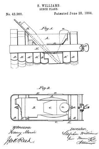
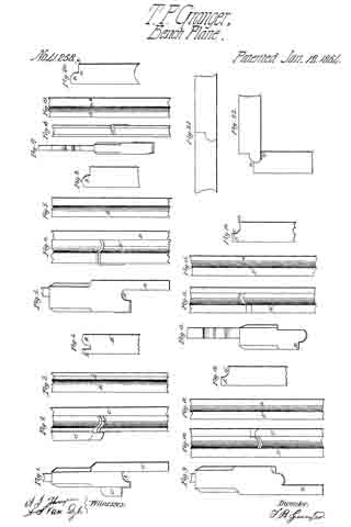
Be it known that I, T. P. GRANGER, of Pecatonica, in the county of Winnebago and State of Illinois, have invented new and useful Improvements in Planes for Jointing Table-Leaves; and I do hereby declare that the following is a full and complete description of the construction and operation of the same, reference being had to the accompanying drawings, making part of this specification, in which —

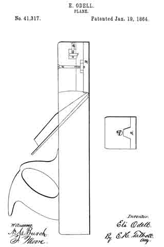
Figure 1 is an end View of the first plane used in forming the bed part of the joint. Fig. 2 is a face view of the same plane. Fig. 3 is an edge view of the bed-leaf after the first plane has been used upon it; and Fig. 4 is an end view of the same. The plane, Figs. 1 and 2, is so formed, as shown at A, as to cut the “round” B on the bed-leaf.

The bed-leaf is first prepared by being jointed on the lower side and edge, the guide C working against the lower side, B’, Fig. 4. A stop, C’, on the opposite side of the plane, by coming in contact with the edge of the leaf B”, determines the depth to which the plane, cuts. Planes, Figs. 5 and 6, show an end and face view of the second plane to be used upon the bed. This is for cutting away B”, Fig. 4, which has been left by the first operation. The guide D works flat against the lower side of the leaf, the groove D’ forming a stop by coming in contact with B, Fig. 3. After the planes, Figs. 5 and 6, have been used the edge of the leaf presents the appearance shown in Figs. 7 and 8. I now use the planes shown in Figs. 17 and 18, for the purpose of cutting the round B to a sharper angle with the square portion of the leaf, as shown at a b in Figs. 19 and 20. This operation finishes the bed-leaf. The fall-leaf is first prepared for making the joint by being jointed upon the under side and upon the joint edge. I then apply the plane shown in Figs. 9 and 10, the guide E working against the under side of the leaf. The face F of the plane coming in contact with the square edge of the leaf F’, determines the depth to which the groove G is cut in the edge of the leaf; but as this plane does not cut the groove G quite deep enough to fit the round B on the bed-leaf. I apply the plane shown in Figs. 13 and 14. The face H coming in contact with the edge F’, determines the depth to which this plane cuts the groove, which is shown complete at c d in Figs.15 and 16. The table-butts are now set in the usual manner, and the leaf presents the structure and adjustment shown in Figs. 21 and 22. A table joint thus constructed presents this peculiar feature, that when the leaf is down, as in Fig. 22, the inner angle of the leaf comes in contact with the under edge of the bed, as at e, and thus raises the fall-leaf higher up on the bed-leaf, as shown at e’, thereby making a better and more durable joint.

What I claim as my improvement, and desire to secure by Letters Patent, is —

The herein-described series of planes for setting table-joints, the same being constructed and used in the manner and for the purpose herein set forth.

T. P. GRANGER.

Witnesses:
A. S. VAN DYKE,
A. J. THOMPSON.

No. 41,317 – Improvement In Planes (Eli Odell) (1864)

[paiddownloads id=”101″]41317


UNITED STATES PATENT OFFICE.

_________________

ELI ODELL, OF WINTERSET, IOWA.

IMPROVEMENT IN PLANES.

_________________

Specification forming part of Letters Patent No. 41,317, dated January 19, 1864.

_________________

To all whom it may concern:

Be it known that I, ELI ODELL, of Winterset, Madison county, and State of Iowa, have invented an Improvement on the Common Plane in two particulars, as hereinafter described, reference being had to the accompanying drawings, and to the letters of reference marked thereon.

The nature of my improvements are in the two following particulars: First, the thread of the plane is to be cut concave, instead of convex, as in the usual term, thus entirely preventing it from choking with shavings, as is customary with the common form; second, improvement is to prevent the enlargement of the throat of plane as the face wears away by use, which is done in the following manner: Cut out to the depth of one inch (more or less) the face of the plane from the throat to the iront end. Then cut a groove in the center of the plane from the front end to the throat on the under side. Then make a separate piece to form that part of the face of the plane cut out, and also to fit the groove accurately. The object of this piece on the face of the plane is to keep the throat of the plane small as the face wears away by use, and is done by cutting the shoulder at the throat of the plane and sliding the face-piece toward the bit, and is represented by the letter B. Thus, the throat may be regulated in size until the plane is worn out. Said face-piece is moved by and held by two screws, the one on the top, letter C, passing through the upper part of the plane and down into letter B into a nut that has play, that it can slide along in a mortise in letter B. The other, in the frontend, (represented by D,) connects with a nut in a mortise in the upper part of the plane, which nut hooks into letter B, which can slide either to open or shut the throat. In order to disconnect letter B (the face-piece) from the plane, unscrew letter C until letter B comes loose.

What I claim as new, and desire to secure by Letters Patent, is —

A plane, with the adjustable face-plate B, in combination with a concave throat, the whole constructed and operated substantially as described.

ELI ODELL.

Witnesses:
JNO. LEONARD,
A. D. NOSLER.

No. 41,983 – Improvement In Plane Stocks (George Franklin Evans) (1864)

[paiddownloads id=”102″]41893


UNITED STATES PATENT OFFICE.

_________________

GEORGE FRANKLIN EVANS, OF NORWAY, MAINE.

IMPROVEMENT IN PLANE-STOCKS.

_________________

Specification forming part of Letters Patent No. 41,983, dated March 22, 1864.

_________________

To all whom it may concern:

Be it known that I, GEORGE FRANKLIN EVANS, of Norway, in the county of Oxford and State of Maine, have made new and important Improvements in the Plane that was patented January 28, 1862; and I do hereby declare the same to be fully described in the following specification, and represented in the accompanying drawings, of which —

Figure 1 is a plan. Fig. 2 is a longitudinal elevation with the face-plate in a straight position. Fig. 3 is a longitudinal vertical section with the face-plate in a convex position. Fig. 4 is a longitudinal elevation with the face-plate in a concave position or reversed from that in Fig. 3. Fig. 5 is a longitudinal elevation of the rabbet and grooving plane with the face-plate in a straight position.

The nature of my improvement consists not only in the manner of making the stock, but in the combination of the arms which connect the ends ofthe spring face-plate to the stock, the same admitting the spring face-plate to be curved either ccnvexly or concavely on its outer surface. These planes are so constructed that they may be more readily adjusted to conform to concave and convex surfaces of diiferent degrees of curvature, whereby such circular parts may be as easily and smoothly planed, grooved, or rabbeted as a plane surface can be by the ordinary straight taced plane.

In the drawings, A is the stock or body of the plane, the same having a throat or shaving passage, B, formed vertically through it, (horizontally in the grooving-plane, Fig. 5.) In the said passage is the plane-iron, which is secured by the leverchip C and the thumb-screw D.

Instead of forming the lower face of the stock A as a straight plane, I cause the same to be curved upward and downward, in the manner as shown in the drawings. To the lower face of the stock I fasten on a flat steel plate by means of ten steel rivets, E E, on the lower part of the throat-passage — five rivets on the forward part and five rivets on the rear part of the throat-passage, as shown in Fig. 1.

Within the two ends of the stock A pass the connecting-rods F F in the form of a segment of a circle. The lower end of each connecting-rod has a hinge-joint, and is received by a socket or hollow pipe with solid ends, which pipe or socket is fastened to the ends of the steel plate G G by means of two steel rivets, I I. In each end of the stock A is a set-screw, H,which holds the connecting-rods F F in position, as shown in Figs. 2 and 4.

A plane constructed on the above-described improved manner can be readily adjusted to plane any circular, concave, or convex piece of wood; also to groove or rabbet the same by simply bending the plate G to the desired position and securing it by means of the connecting-rods F F and the set-screws J J.

From the above and by inspection of the drawings it will be perceived that my improved plane has its stock formed with two curved ends or projections extending from the part B, which hold the plane-iron, and so adapted to receive the curved arms F F as to allow them to play or move in curved paths both toward and away Ironi the said part B. Now, this mode of making the plane-stock not only enables the spring face-plate to be bent either into a convex or concave form, but it renders the curved ends or projections very convenient as handles by which the plane may be held and operated. Furthermore, they not only give to the connections F F a long range of motion, but keep their upper ends always within the stock when the face-plate is convex on its outer surface, there being no projection of the connections F F above the top surface of the plane-stock when the G is bent to its extreme position, as shown in Fig. 3.

What, therefore, I claim as my invention or improvement in the plane made with the spring face-plate is —

The construction of the connecting-rods F F and their receiving parts of the stock, curved substantially in the manner and so as to operate together as specified.

GEORGE FRANKLIN EVANS.

Witnesses:
HENRY UPTON,
C. C. SANDERSON.

No. 42,585 – Improvement In Grooving Or Panel Plows (William S. Loughborough) (1864)

[paiddownloads id=”103″]42585


UNITED STATES PATENT OFFICE.

_________________

WILLIAM S. LOUGHBOROUGH, OF ROCHESTER, NEW YORK.

IMPROVEMENT IN GROOVING OR PANEL PLOWS.

_________________

Specification forming parts of Letters Patent No. 42,585, dated May 3, 1864.

_________________

To all whom it may concern:

Be it known that I, WM. S. LOUGHBOROUGH, of Rochester, in the county of Monroe and State of New York, have invented a new and useful Panel-Plow or Grooving-Plane; and I do hereby declare that the following is a full, clear, and exact description thereof, reference being had to the accompanying drawings, making a part of this specilication, in which —

Figure 1 is an elevation of the left side of the plane. Fig. 2 is an elevation of the right side. Fig. 3 is an end view of the fence B detached, showing the front arm, C.

Similar letters of reference indicate corresponding parts in the several figures.

The nature of my invention consists, mainly, in the peculiar construction of the stock of panel-plows or other grooving-planes ; also, in a novel and efficient means for securing the adjustment of the fence by simply turning one screw, and in an improved manner of securing the bits in this class of planes.

A in the drawings represents the skeleton stock; B, the fence; C and C’, the arms; D, the thumb-screw ibr fastening the bit; E, the screw for fastening the arms of the fence; a, the screw for holding the stop S ; G, the bit ; b and b’, the clamping-bars, and w the wedge, which is operated upon by the screw E, by which it is driven down between the end of the bars b and b’, causing them to clamp firmly against the arms of the fence and to hold it securely in position. The wedge should be made sufficiently obtuse to cause it to recede from between the bars whenever relieved by the screw.

The body or stock A of the plane is made, as seen in the drawings, with an enlargement, d, running diagonally across and projecting equally on each side. Within this enlargement is formed a mortise, through which the bit G is placed. This mortise should be five-eighths to three-fourths of an inch wide, and it is recessed on the front or upper side, as indicated by the dotted lines, which is done by enlarging the core. Said core should also have a projection on the right side, near the lower end, to form the opening under the clasp f for the bar b1’ to pass through. The clasp g is formed by “coping out” in molding, part ofthe stop being removed, as seen in Fig. 1, to show the recess. The oval-shaped recess in which the wedge w is placed is formed in the same manner, and is made deep enough to receive the upper end of the bars b and b’ and the thickness of the flange i. The clasp g is extended over the upper rib of the arm G, and a similar bearing is provided over C’ by the projection a. These bearings prevent the arms from “tilting” when released by the screw E. The projections J should be long enough to prevent any cramping of the arms when the fence is being moved either way, and also to secure its parallel movement, it being cast or otherwise rigidly fixed to the arms.

The stop S is secured between the diagonal ribs r by the screw a, which may have a milled head, if desired. The ribs r are cast with the stock, and they receive all the diagonal strain coming upon the stop, thereby relieving the screw a from all lateral strain. The stock A is thickened by the button u (seen in Fig. 2) to increase the threaded bearing ofthe screw a.

The arch N of the throatway may be formed on either side ofthe stock, but the right hand side is probably preferable.

The bits G are made of uniform thickness from end to end, and are provided, the same as other plow-bits, with a central groove in the back side, which rides the front end of the rear plate, P’, and they are so fitted in the mortise as to have a bearing at t before they strike the rest at v, against which they are forced by the screw D and firmly held. This manner of fitting the bits, always effecting a perfect bearing of the bit at t, whether a wide or narrow one is used, insures the discharge of the shavings.

The plate p projects each side across the stock so as to form the seat for the handle H centrally behind the bit. The handle is held against the side plate, lt, by the screw s, and the rear end is firmly held in position by a screw through the base plate p at y.

The fence B may be removed at any time without deranging the clamping devices, the flange i of the wedge to preventing the end of the bars b and b’ from falling out. There is a shoulder on the back side of b’ at e, Fig. 2, which strikes against the case of the bit-mortise, and thus prevents the bar from dropping away from the flange i, and b is kept in position longitudinally by the point c resting against the stock.

If desired, the arms G and C’ may be made separate from the fence B and attached thereto by screws or otherwise; but I prefer to cast them together, as shown in the drawings.

Among the many advantages afforded by making these tools of metal instead of wood are the following: They are much less cumber-some, are more durable, the parts are much more readily and perfectly adjusted, they work better and easier, because they never choke or clog with the shavings, and they can be sold for less than one-half the cost of wooden planes of the same variety.

The plates P and P’ are cast on the stock A, thereby avoiding the labor and expense of fitting and attaching them by screws or other-wise.

What I claim as my invention, and desire to secure by Letters Patent, is —

1. The above-described panel plow or plane, when constructed, arranged, and combined in the manner and for the purposes specified, as a new article of manufacture.

2. Securing the gage of the fence B at any desired point by operating a single screw, E, substantially in the manner specified.

WM. S. LOUGHBOROUGH.

Witnesses:
A. C. DICKINSON,
A. H. BILLINGS.

No. 43,053 – Improvement In Bench Planes (Richard Washburn) (1864)

[paiddownloads id=”104″]43053


UNITED STATES PATENT OFFICE.

_________________

RICHARD WASHBURN, OF RAMAPO, NEW YORK.

IMPROVEMENT IN BENCH-PLANES.

_________________

Specification forming part of Letters Patent No. 43,053, dated June 7, 1864.

_________________

To all whom it may concern:

Be it known that I, RICHARD WASHBURN, of Ramapo, in the county of Rockland and State of New York, have invented a new and useful lmprovement in Bench-Planes; and I do hereby declare that the following is a full, clear, and exact description of the same, reference being had to the accompanying drawings, forming apart of this specification, in which —

Figure 1 is a longitudinal vertical section of my invention. Fig. 2 is a plan or top view of the same. Fig. 3 is a detached perspective view of the slotted wedge which I use to secure the plane-iron.

Similar letters of reference indicate corresponding parts in the several figures.

This invention consists in the employment or use of a slotted wedge inserted in suitable guide-grooves in the front side of the throat of a plane, and adjustable by means of a set-screw, in combination with the plane-iron in such a manner, that by means of said slotted wedge and set-screw the plane iron can be firmly secured in the desired position, and by the point of the wedge the shavings are thrown oif from the cutting-edge of the iron and caused to pass up through the throat of the plane with ease and facility, and the use of a double iron can be dispensed with.

A represents the body of my plane, which is made of wood or any other suitable material, and provided with a throat, B, through which the plane iron C passes in the usual manner.
The plane-iron is secured in the throat by means of a slotted wedge, D, a detached perspective view of which is shown in Fig. 3. This wedge is guided in grooves a in the front side of the threat, and it is secured in its place by means of a set-screw, b, which passes freely through its top and screws into a nut fastened in the upper surface of the body A of the plane. The lower inclined surface, c, of the slotted wedge fits nicely on the upper surface of plane-iron, as clearly shown in Fig. 1, and its front edge is chamfered off in the opposite direction to that of the plane-iron, so that the shavings are thrown off from said cutting-edge, and that the inclined plate c of the slotted wedge takes the place of the ordinary double iron. By releasing the set-screw b the plane-iron can be easily adjusted up or down without the use of the hammer, and by tightening said set-screws the slotted wedge is firmly pressed down on the plane-iron and the latter is securely held in the required position. The sole of the plane is protected by a plate, E, secured to the front edge of the same by means of set screw d. This screw passes through an oblong hole, e, in the body of the plane, so that the plate E can be easily adjusted backward or forward and that by these means the mouth of the plane can be enlarged or diminished at pleasure. The plate E therefore serves the double purpose of protecting the sole of the plane and of making its mouth adjustable.

The improvements herein described are applicable to planes of every description, and it is obvious that the slotted wedge can be used independent of the adjustable plate E, or in combination with the same, as may be desired.

What I claim as new, and desire to secure by Letters Patent, is —

The slotted wedge D, secured in the throat of a plane, A, by means of a set-screw, b, and operating in combination with the same and with the plane-iron C, substantially in the manner and for the purpose specified.

RICHARD WASHBURN.

Witnesses:
DANIEL COOPER,
JAMES SUFFERN.

No. 43,360 – Improvement In Bench Planes (Stephen Williams) (1864)

[paiddownloads id=”105″]43360


UNITED STATES PATENT OFFICE.

_________________

STEPHEN WILLIAMS, OF PHILADELPHIA, PENNSYLVANIA.

IMPROVEMENT IN BENCH-PLANES.

_________________

Specification forming part of Letters Patent No. 43,360, dated June 28, 1864.

_________________

To all whom it may concern:

Be it known that I, STEPHEN WILLIAMS, of Philadelphia, in the county of Philadelphia and State of Pennsylvania, have invented a new and useful Improvement in Smoothing-Planes; and I do hereby declare that the following is a full, clear, and exact description thereof, which will enable others skilled in the art to make and use the same, reference being had to the accompanying drawings, making a part of this specification, in which —

Figure 1 is a side sectional elevation of my invention. Fig. 2 is a. plan view of the same.

Similar letters of reference indicate like parts.

I denominate my improvement the “universal smoothing-plane,” because it belongs to that variety of planes in which the face is made changeable, so that it may be conveniently adapted to the planing of curved as well as straight surfaces.

By the use of my improvement surfaces that are convex, concave, or straight may be easily worked, the thee of the tool being readily changed from one form to another to suit the surface to which it is to be applied.

A is a hollow box, of the exterior form shown, made, in one or more pieces, of iron or other materials, receiving the usual wedge, B, and plane iron C, which passes obliquely through the box A, a nipple, a, at its front end to receive the blow of the hammer during adjustment. The remaining body of the plane is composed of movable sections or blocks D, filted together, some of them, D’, made to conform at their upper ends to the shape of the box A, against which said ends press, as shown. The blocks or sections D D’ and the box A are bound together by an exterior hoop or band, E, of metal, which incloses them. The end piece, b,.of the band E is made sufficiently thick at its middle to have formed in it a screw-nut, through which a binding-screw, F, passes to press against the outer section or block, D, as shown. By turning the screw F the blocks or sections D D’ and box A will all be firmly bound or pressed together, and, as their lower ends constitute the surface of the plane, it is only necessary, in order to change the form of the face of the plane, to vary the position of the sections and box in respect to each other and then bind them by the screw F. Upon each alternate surface of the sections D D’ and box A there is a tongue and groove, c, d, which prevents lateral displacement of the sections, but allows of vertical adjustment. Upon the exterior of box A there are projecting tongues or ledges e e, between which the band E passes. These ledges prevent the displacement of the band E. The lower extremities of the sections D D’ and box A are made slightly rounded, so as to afford greater facility in moving the plane, prevent the edges of the sections from catching on the surface of the work, &c.

The black lines in Fig. 1 show the plane as adjusted to plane a concave surface. The red lines show the position of the parts when adjusted to plane a flat surface, and the blue lines show the adjustment for a convex surface.

I do not confine myself to the precise form of parts herein shown, as that may be varied according to the skill of the maker; but,

Having thus described my invention, I claim as new and desire to secure by Letters Patent —

1. The construction of the body ofthe plane of movable blocks or sections, substantially in the manner and for the purpose herein shown and described.

2. The combination of the movable sections D D’, independent plane bit-holder A, inclosing-band E, and screw F, all arranged and employed as described.

STEPHEN WILLIAMS.

Witnesses:
HENRY MCNEILL,
HENRY BENJAMIN.