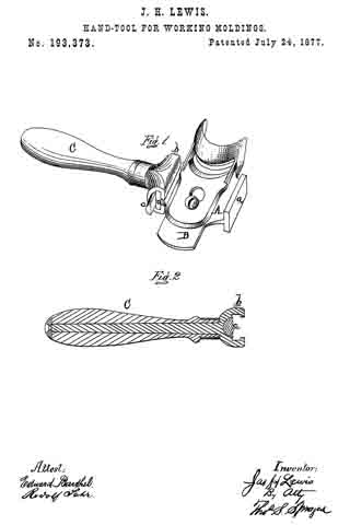
No. 198,180 – Improvement In Bench-Planes (Heinrich Baecker) (1877)

[paiddownloads id=”287″]198180


UNITED STATES PATENT OFFICE.

_________________

HEINRICH BAECKER, OF REMSCHEID, GERMANY.

IMPROVEMENT IN BENCH-PLANES.

_________________

Specification forming part of Letters Patent No. 198,180, dated December 18, 1877.; application filed October 8, 1877.

_________________

To all whom it may concern:

Be it known that I, HEINRICH BAECKER, of Remscheid, Germany, have invented Improvements in the Construction of Planes, of which the following is a specification:

This invention relates to bench-planes, the common form of which consists of a stock in which the plane-iron is fastened by means of wedges. These plane-irons are, in their main part, composed of an iron plate, to the end of which a strip or facing of steel is attached to form the cutting-edge. Such planes are deficient in many respects. They are rendered expensive by the forging operation necessary to unite the main part of the plane-iron and its steel facing, which mode of manufacture often ruins the structure. The mode of their production frequently renders the said irons defective by destroying the high quality required for the steel cutting-edge. Such irons require to be bulky, and therefore more difficult to grind, and on account of the limited extent of their steel portion must soon be destroyed when frequently ground.

My invention relates to that class of planes wherein the iron or bit is composed of a plate having an even thickness, and composed entirely of steel — such an iron or bit as may be sharpened until its length is so diminished that it can no longer be supported in the stock.

My invention consists in the means for securing and adjusting such an iron or bit in the plane-stock, the details of which are too fully hereinafter set forth to need preliminary description.

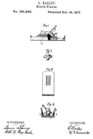
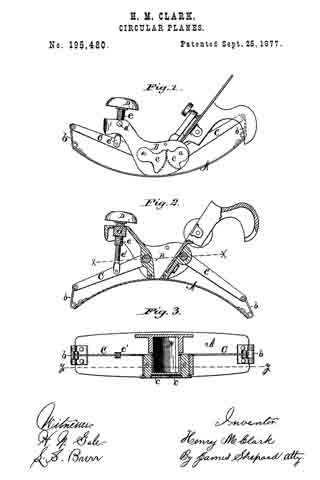
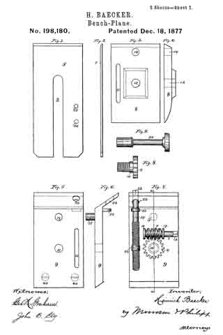
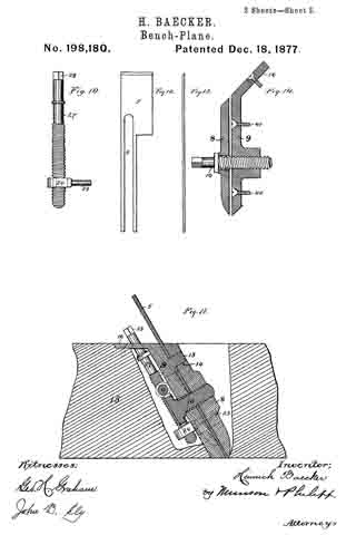
In the accompanying drawings, illustrating my invention, in which like reference-characters indicate the same parts, Figure 1 is a plan view, and Fig. 2 an edge view, of the plane iron or bit; Fig. 3 is a plan view, and Fig. 4 an edge view, of the upper break-iron. Fig. 5 is a plan view, and Fig. 6 an edge view, of the under break-iron, with the adjusting mechanisms attached; Fig. 7, a view of the clamping mechanism. Fig. 8 shows the clamping-screw, and Fig. 9 an operating-key. Fig. 10 shows an adjusting-screw. Fig. 11 is a vertical section of all the parts fitted together in operative position. Fig. 12 is a plan view, and Fig. 13 an edge view, of a rabbet-plane iron, and Fig. 14 is a modification of the mode of fastening the iron or bit in place.

The steel iron or bit 5 is composed of a thin sheet of steel, of even thickness, which is sharpened at its bottom edge, and it is provided with a slot, 2, extending centrally from its top edge to a distance beyond its middle part. It is adjusted in the plane-stock between two break-irons, 8 9, one of which (the lower, 9) is secured to the plane-stock. The iron or bit lies between these break-irons, as in Fig. 11, and the said devices are fastened securely together by means of a clamping-screw, 10, whose stem passes through a hole, 11, in the under break-iron 9, through the slot 2 in the iron or bit, and enters a screw-threaded hole, 12, tapped into the upper break-iron 8. When the iron or bit is properly adjusted between these break-irons, it may be firmly secured by properly tightening said clamping-screw. The upper break-iron 8 and the plane iron or bit are prevented from moving laterally with respect to the under break-iron 9 by means of a pin, 13, projecting from the inner face of the under break-iron 9, passing through the slot 2 of the iron or bit, and entering a hole, 14, in the upper break-iron 8. The parts thus held together are secured in the mortise in the plane-stock 15 by means of an arm, 16, projecting rearward from the under break-iron, and fastened to the stock 15 by means of a screw. The lower end of the under break-iron rests upon one side of the mortise, where it is secured by screws 40, while the front surface of the end of the upper break-iron rests upon the other side of said mortise, the devices being thus held steadily in place.

In order that the iron or bit 5 may be adjusted while its break-irons are hired in the mortise in the plane-stock, the head 6 of the clamping-screw is provided with gear-teeth, fitting a worm, 4, the shank 7 of which turns in arms 17 18 projecting from the rear face of the under break-iron 9. The shank 7 of this worm is provided with a squared head, 19, which fits a similar socket in a turning-key, 20.

By these devices the said clamping-screw 10 may be turned in and out of the screw-threaded hole 12 by inserting the key 20 through a hole (not shown) in the side of the plane-stock, engaging the same with the head 19 and operating said key in the proper direction.

In order to adjust the plane-iron vertically with respect to the break-irons and plane-stock, and thus protrude its cutting-edge the desired distance, each of the break -irons is provided with slots in which a pin connected with said plane-iron may freely play. The slot in the upper break-iron is marked 21, and that in the lower break-iron is marked 22. The pin 23, operating the iron 5, projects from a hub, 24, and enters one of two holes, 25 26, with which said plane-iron is provided. An ad-
justing-screw, 27 , having a screw-threaded shank, which runs in a threaded hole tapped through the hub 24, is supported in a collar, 30, fast to the underbreak-iron, and its squared head (adapted to fit the socket of the turning-key 20) projects above the plane-stock. This construction permits the rotation of said screw 27 to raise or lower the hub 24, and to impart a like movement to the plane-iron without disturbing the break-irons.

It is evident that in order to adjust the plane-iron in either direction the clamping-screw 10 must be first loosened, whereupon the adjusting movement may be imparted by means of the adjusting-screw 27. This done, the iron may be again secured by operating the clamping-screw 10.

Furthermore, if it is desired to remove the plane-iron it may be done when the break-irons are adjusted so as not to clamp and hold the said iron.

In the modification , Figs. 12, 13, 14, which represent the irons of a rabbet-plane, the devices are constructed substantially as before described, except that the adjusting-screw 27 is omitted, and the clamping-screw is adapted by means of a squared head to be operated by means of the turning-key, which operation may be the more readily effected by having the head of said screw project from the front side of the upper break-iron, the under break-iron, in this instance, being provided with the screw-threaded hole 12.

What is claimed is —

1. The combination of the plane iron or bit 5, upper and under break-irons 8 9, and clamping-screw 10, substantially as described.

2. The combination of the plane iron or bit 5, upper break-iron 8, having hole 14, under break-iron 9, having projecting pin 13, and clamping-screw 10, substantially as described.

3. The combination of the plane iron or bit 5, break-irons 8 9, clamping-screw 10, worm 4, and geared head 6, substantially as described.

4. The combination of the break-irons 8 9, having slots 21 22, with the plane iron or bit 5, having a slot, 2, pin 23, and adjusting-screw 27, substantially as described.

5. An improved plane, consisting of a bit having an equal thickness throughout its length, and a slot, 2, break-irons 8 9, clamping-screw 10, and an adjusting mechanism, as screw 27 and pin 23, substantially as described.

In testimony whereof I have signed my name to this specification in the presence of two subscribing witnesses.

HEINRICH BAECKER.

Witnesses:
BERNH. SCHENK,
FRANZ MAYENBARN.

No. 196,450 – Improvement In Bench-Planes (Charles H. Hawley) (1877)

[paiddownloads id=”286″]196450


UNITED STATES PATENT OFFICE.

_________________

CHARLES H. HAWLEY, OF HARTFORD, CONN., ASSIGNOR TO LEONARD BAILEY, OF SAME PLACE.

IMPROVEMENT IN BENCH-PLANES.

_________________

Specification forming part of Letters Patent No. 196,450, dated October 23, 1877; application filed October 1, 1875.

_________________

To all whom it may concern:

Be it known that I, CHARLES H. HAWLEY, of Hartford, in the county of Hartford and State of Connecticut, have invented an Improvement in Bench-Planes, of which the following is a specification, reference being had to the accompanying drawings, where —

Figure 1 is a side view with a part of the side of the plane broken away. Fig. 2 is a top view, with the plane-iron and cap-plate removed. Fig. 3 is a view of the parts shown in Fig. 2 in transverse vertical section, on plane x x, looking in the direction indicated by the arrow. Fig. 4 is a top view of the cap-plate. Fig. 5 is a bottom view of the iron.

The plane is a metallic one — body, &c., of cast-iron, by preference.

The letter a denotes the floor of the plane, and b b the sides, cast in one piece with the floor; c, a transverse upright, cast in the same piece to which is secured the bed d by screws e e. On this bed lies the plane-iron f, its front end running down to the throat. Underneath the bed is hung, on pin g, the scroll-disk h, which rotates on the pin. A grooved scroll is cut into the upper face of disk h. (Partly seen in Fig. 2.) In the bed d is hung the reciprocating follower i, through which runs the pin j, fast in the follower, its lower end projecting into the scroll-groove, and its upper end projecting, when the plane-iron is in its place, into one of the transverse grooves f’, made in the under side of the plane-iron, so that the iron must then reciprocate longitudinally with the follower i. These reciprocations are given by the rotation of the scroll-disk, and the purpose thereof is to allow the fine longitudinal adjustment of the plane iron or bit.

The location of the scroll-disk just underneath the plane-iron bed is important, as it enables me to make direct connection between the scroll-disk and the iron or bit without the intervention of levers and the like, and it brings this disk into position for manipulation by the workman.

I am aware of the patent of J. A. Traut, January 16, 1877, No. 186,281, wherein the scroll-disk is applied directly to the chisel or plane-iron; but this construction is objectionable, in that the rotation of the disk moves the chisel sidewise, and makes it bind; and it also disturbs the true adjustment of the cutting-edge.

I am also aware of the patent of J. F. Baldwin, November 25, 1873, No. 144,823, which shows a slide or other device intermediate between the plane-iron or chisel and an adjusting-screw; but this construction is likewise objectionable and defective, and neither attains the same ends as a scroll for operating a plane-iron, between which is interposed a follower independent of both, but co-operating therewith.

This last-named construction is peculiar to my plane, and has marked advantages over the other, and especially in that by it I am enabled to adjust the chisel accurately and easily.

The essential feature of my invention is , thus, the independent intermediate follower, constructed and arranged as above specified.

The cap-plate is serves to secure the iron or bit in its place when adjusted. It is provided on the sides with wings k’, which slide into slots or mortises l, cut obliquely in the inner faces of the two sides of the plane-body, entering at the rear ends of these slots.

The cap-plate, when in place, acts as a lever, of which the wings k’ are the fulcra, and by turning down the screw m, the iron or bit is pinched by the front end of the cap-plate and by the screw.

This method of giving fulera has important advantages. The whole space between the sides of the body is left open and unobstructed, so that the chisel can be laid flatly down to its place without having to shove it under a cross-bar, or under lugs projecting from the sides, as has been the practice heretofore.

In these planes, which have no regular handle, it is necessary to have something to serve in the place thereof for the palm of the hand to rest upon. I attain this end by putting a semi-sphere or convex plate, a, upon the head of the screw m, which is thereby made to serve the purpose of a handle, and of a head for the screw.

I claiam as my invention —

The independent follower i, arranged between the scroll-disk and the chisel, and having pin j projecting from both sides, so as to enter the serrations f’ in the plane iron or bit f on one side, end the groove or channel in the scroll-disk h, on the other side, substantially as and for the purpose described.

CHARLES H. HAWLEY.

Witnesses:
JAMES HOLLEY,
ROALD ARENTZ.

No. 196,444 – Improvement In Bench-Planes (Wilhelm Grüssler) (1877)

No. 196,444 – Improvement In Bench-Planes (Wilhelm Grüssler) (1877)

[paiddownloads id=”285″]196444


UNITED STATES PATENT OFFICE.

_________________

WILHELM GRÜSSLER, OF RUISSEINA, NEAR NOSSEN, SAXONY, ASSIGNOR TO CARL PIEPER, OF DRESDEN, GERMANY.

IMPROVEMENT IN BENCH-PLANES.
_________________

Specification forming part of Letters Patent No. 196,444, dated October 23, 1877; application filed October 15, 1877.

_________________

To all whom it may concern:

Be it known that I, WILHELM GRÜSSLER, of Ruisseina, near Nossen, in the Kingdom of Saxony, have invented a new Cornice-Plane, of which the following is a specification:

This invention consists in constructing the irons of molding, cornice, and similar planes, as well as the cutters of wood-planing machines, in such a manner that they may be sharpened upon common grinding-surfaces, whereby filing or otherwise trimming the molded surface at the cutting-edge is avoided.

A molding-plane provided with my improved iron is illustrated in the drawings, Figure 1 illustrating a side elevation of the same; Fig. 2, a part right-hand end view; Fig. 3, a part longitudinal section, and Fig. 4 a cross-section on line Y Z of Fig. 3. Figs. 5 and 6 illustrate modified forms of the invention; and Fig. 7 represents cutters constructed according to this improvement, and applied to the tool-holder of a wood-planing machine.

The plane-iron a may be curved, as shown in Figs. 1 and 3, or straight, as represented in Figs. 5 and 6. It is molded throughout the length of its back surface, as is shown in the sectional view, Fig. 4; but, if preferred, this molding may extend along a part only of the back surface.

The body or stock is, by preference, to be made of metal, although wood or other suitable material may be used, and the iron fastened to the part b of the stock by a screw-bolt, d, passing through a slot in said part b, and provided with a fastening-nut, having a milled edge or in any other suitable manner.

The part b must correspond along its face or outer side with the molded surface of the iron, and a strip of cloth or other suitable material, c, should be placed under the iron, for the purpose of increasing the friction of the same, and to prevent the iron from shifting. This strip of cloth may be glued to the part b.

The iron must be molded on its back surface in such a shape that, after being ground at the end to the proper bevel and fixed in position, its cutting-edge will correspond to the molded face e of the plane.

The curved form affords great facilities in manufacturing the irons, since they may be turned in a lathe in a large ring, which is subsequently cut into pieces; but, if preferred, these irons may be made straight, as in Figs. 5 and 6.

In the modihcation, Fig. 5, the screw d is fixed in the body of the plane, and the iron has a slit in it to provide for its adjustment.

In the modification, Fig. 6, a straight iron has its flat upper surface fixed to the under side of a plate, o, projecting from a side wall of the plane-stock, whereby contact of the molded back surface of the iron with its support is avoided.

The beveled end surface V W, Figs. 3, 5, and 6, which is, by preference, flat, so that it may be ground on any common grindstone, is turned or faced upward and toward the front or leading end of the plane, while heretofore it has commonly been turned or faced the other way. This beveled surface should be inclined to the face of the plane at the same angle at which the body of the irons in common planes is inclined, while the angle of inclination of the molded back surface at the cutting-edge has in general to agree with that of the bevel of the common irons.

The handles f and g of the plane represented in Fig. 1 may be modified in various ways; but considering the number and variety of molding-planes required in a joiner’s shop, I regard it advantageous to make the bottom part, which has the molded face e, in one piece with the part b, and to have a separate piece provided with the handles f and g, adapted to fit all the main pieces in such a manner that it may be readily fixed to any one of them.

For the purpose of enabling the user to plane a number of moldings to exactly the same depth, an adjustable stop, k, Figs. 2 and 5, may be screwed laterally to the stock of the plane, thereby forming a gage, limiting the depth of the cut.

These improved plane-irons may be applied to molding-planes of all descriptions — such as grooving, tonguing, rabbeting, and similar planes, as well as to ordinary planes with flat faces. They may also be used for machine-planing, as shown in Fig. 7, which illustrates the section of a rotating tool-holder of a wood-planing machine fitted with the improved cutters a a. These are molded on the beck surface or outside in the some manner as stated ebove. For fixing them to the holder b’, a washer, h, molded to correspond to the cutter, is placed under the nut of the fastening-screw.

What is claimed is —

1. A plane iron or cutter molded on the back part or surface to the desired pattern throughout the whole or at part of its length, and being flat on its upper surface, in combination with a plane-stock or tool-holder shaped to fit the molded side of the iron, all substantially as and for the purpose set forth.

2. The combination of a plane iron or cutter, a plane-stock or tool-holder, and an interposed strip of fabric, substantially as and for the purpose set forth.

In testimony whereof I have signed my name to this specification in the presence of two subscribing witnesses.

WILHELM GRÜSSLER.

Witnesses:
ERASMUS PAUL,
MAXIMILIAN SGHÜNE.

No. 196,068 – Improvement In Bench-Planes (Leonard Bailey) (1877)

[paiddownloads id=”284″]196068


UNITED STATES PATENT OFFICE.

_________________

LEONARD BAILEY, OF HARTFORD, CONNECTICUT.

IMPROVEMENT IN BENCH-PLANES.

_________________

Specification forming part of Letters Patent No. 196,068, dated October 16, 1877; application filed June 29, 1877.

_________________

To all whom it may concern:

Be it known that I, LEONARD BAILEY, of Hartford, in the county of Hartford and State of Connecticut, have invented certain new and useful Improvements pertaining to a Metallic Plane, of which the following is a specification, reference being had to the accompanying drawings, where —

Figure 1 is a side view with a portion broken away to show operating parts. Fig. 2 shows a form of the nut. Fig. 3 is a view of the back of the iron. Fig. 4 is a sectional view of Fig. 1, on plane x x, and looking toward the working parts, the iron being removed.

This invention relates to the construction and adjustment of iron-bodied planes, designed for a class of work exemplified by stake-pointing and whip-stock manufacture.

The letter a denotes the cast-metal body, having the sides and ends concaved or hollowed, as seen in the sectional part of Fig. 1, for the purpose of giving the user a firm grasp of the tool.

On the inner faces of the two sides are cast lugs b b, afterward sawed or cut through where they join the throat-bed c, so that the iron may be confined between these lugs and the throat bed.

From the base-plate of the plane-body rises a boss or stud, d, and from this a screw-threaded stud, e, projects toward, at right angles to the surface of, the iron. On this threaded stud e is hung the nut f, provided with projecting radial arms, whereby it may be rotated readily.

This nut may be shaped as shown in Fig. 2, and in that case bears directly against the iron when screwed up.

It will be observed that the iron has three points of bearing — viz., the throat-bed, the lugs b b, and the nut just described, needing no cap-plate, and forming the simplest possible means of fastening an iron into a metal plane.

I claim as my invention —

1. A metallic plane-body having the sides curved or hollowed, as described, and for the purpose set forth.

2. In combination, the screw e, nut f, and pin-disk j, borne upon the screw, and the grooved plane-bit, all substantially as described.

LEONARD BAILEY.

Witnesses:
W. E. SIMONDS,
ROBT. F. GAYLORD.

No. 195,481 – Improvement In Bench-Planes (Henry M. Clark) (1877)

[paiddownloads id=”283″]195481


UNITED STATES PATENT OFFICE.

_________________

HENRY M. CLARK, OF NEW BRITAIN, CONNECTICUT.

IMPROVEMENT IN BENCH-PLANES.

_________________

Specification forming part of Letters Patent No. 195,481, dated September 25, 1877; application filed August 6, 1877.

_________________

To all whom it may concern:

Be it known that I, HENRY M. CLARK, of New Britain, in the county of Hartford and State of Connecticut, have invented certain new and useful Improvements in Devices for Adjusting Plane-Irons, of which the following is a specification:

My invention consists in the employment of a transverse slide. provided with an inclined slot and operating screw, and also in the peculiar construction of the parts, as hereinafter described.

In the accompanying drawings, Figure 1 is a side elevation of a device for adjusting plane-irons which embodies my invention. Fig. 2 is a sectional view of the same on line x x of Fig. 1, with cap and plane-iron removed, the same being viewed from a point at right angles to the face of the frog; and Fig. 3 is a transverse section of the same on line y y of Fig. 2.

The stock A may be any of the ordinary kinds, and the frog B can be secured thereto in any proper manner. Transversely to the frog B is a recess or depression, a, which is made shallow on the right-hand side of the frog and deep on the left-hand side of the frog. The body of a screw, b, passes through the solid metal of the frog just under the shallow portion of the depression a, and the screw proper extends into the deeper portion of said depression.

The outer end of the screw b is provided with a suitable head or handle, c, for operating said screw, and it is prevented from longitudinal movement by shoulders at each end of its bearing in the frog.

Fitted to move in the depression a is a slide, C, having an inclined slot, d, and threaded lug e, through which lug the screw b passes. By turning the screw the slide may be moved endwise either to the right or left, as may be desired.

Another slide, D, is fitted to slide longitudinally in a recess in the frog B, and the upper end of this longitudinal slide is provided on its under side with a projecting pin or stud, f Fig. 3, also indicated by broken lines in Fig. 2, which pin or stud engages the side walls of the inclined slot in the slide C. In the lower end of the longitudinal slide is an orifice to receive the head of the ordinary cap-screw, which orifice, g, Fig. 2, may be elongated somewhat from right to left, so that the plane-irons F may be moved sidewise a little to bring the end of the cutting-bit square with the face of the stock.

When the transverse slide is moved endwise, by means of the operating screw, the side walls of the inclined slot d engage the pin or stud f and move the longitudinal slide and plane-irons.

If the slide C is moved to the right, the Iongitudinal slide D is forced downward, carrying the plane-irons with it, and, if moved to the left, the plane-irons are drawn upward into the stock with said slide.

If desired, instead of connecting the longitudinal slide to the plane-irons through means of the ordinary cap-screw, a stud may be attached directly to the cutting-iron, and received in the orifice at the lower end of the longitudinal slide.

My adjustment is very cheaply constructed, and adjusts the plane-iron with ease and smoothness.

I claim as my invention —

1. In a device for adjusting plane-irons, the transverse slide, provided with inclined slot and operating mechanism for moving said slide transversely to the plane-iron, substantially as described, and for the purpose specified.

2. In a device for adjusting plane-irons, the screw b, set transversely to the frog, and secured from longitudinal movement, in combination with the incline slotted slide, provided with threaded lug e, which receives the adjusting-screw, substantially as described, and for the purpose specified.

HENRY M. CLARK.

Witnesses:
T. A. CONKLIN,
JAMES SHEPARD.

No. 195,480 – Improvement In Circular Planes (Henry M. Clark) (1877)

[paiddownloads id=”282″]195480


UNITED STATES PATENT OFFICE.

_________________

HENRY M. CLARK, OF NEW BRITAIN, CONNECTICUT, ASSIGNOR TO THE STANLEY RULE AND LEVEL COMPANY, OF SAME PLACE.

IMPROVEMENT IN CIRCULAR PLANES.

_________________

Specification forming part of Letters Patent No. 195,480, dated September 25, 1877 application filed August 6, 1877.

_________________

To all whom it may concern:

Be it known that I, HENRY M. CLARK, of New Britain, in the county of Hartford and State of Connecticut, have invented certain new and useful Improvements in Circular Planes, of which the following is a specification:

My invention consists of a connecting mechanism for the two ends of the flexible bottom of a circular plane, so that they necessarily move together, in combining therewith a single operating device, in the peculiar construction of parts, and in their combination, as hereinafter described.

In the accompanying drawings, Figure 1 is a side elevation of a circular plane, which embodies my invention. Fig. 2 is a vertical section of the same on line y y of Fig. 3, and Fig. 3 is a horizontal section of the same on line x x of Fig. 2.

In Fig. 1 the flexible bottom A is set in a convex position for dressing a concave surface, and in Figs. 2 and 3 it is set in a concave position for dressing a convex surface.

Circular planes having a flexible bottom and mechanism for holding the same when set in various circles are old; but, so far as I know, the two ends of the flexible bottom have never before been so connected as to necessitate their simultaneous movement. These prior planes had no mechanism for moving the ends of the flexible bottom, but only mechanism for holding the ends in place when moved by hand; and these holding mechanisms were entirely independent of each other, so that unless great care was taken in setting the bottom, one end would be bent to conform to one sized circle and the other end to conform to a circle of a different size.

The object of my invention is to adjust the flexible bottom more conveniently than heretofore, and to always adjust both ends to the same circle.

The flexible bottom A is secured to the stock B by screws taking into the stock at each side of the throat, in the usual manner of securing the same in circular planes.

At one side of the stock B short shafts a a are secured in proper bearings, so as to partially rotate therein. On the inner ends of said shafts a a, and in the middle of the stock B, rocking levers C C are rigidly secured, so as to rotate with said shafts. The outer ends of the rocking levers C C are connected to the ends of the flexible bottom A by means of the links b b.

On the outer ends of the shafts a a, rigidly secured, are segment-gears c c, which mesh into each other and necessitate the movement of one shaft with its fellow.

Inasmuch as the rear end of the flexible bottom is longer than its front end, and describes a larger circle in bending, the segment-gear on the front or short end is made larger than the segment-gear on the long end, in order to cause the latter to move enough faster than the former to compensate for the difference in the size of the circle described by the two ends of the flexible bottom.

In the front end of the stock B there is a rocking block or nut, d, which receives the adjusting-screw e, surmounted by a suitable knob or handle, D. The screw e is also provided with an internal thread, running in the opposite direction from that of its external thread, which internal thread receives the adjusting-screw e’, the lower end of which is connected by a pin or other jointed connection to one of the levers.

By turning the adjusting-screw e e’, the lever C, to which it is connected, is either depressed or lowered, according to which way the screw is turned, thereby partially rotating the shaft a. The segment-gear on the outer end of the shaft, meshing into a like gear on its fellow shaft, carries the opposite lever with the one connected to the screw, and the ends of the flexible bottom being connected by the links to said levers, as shown, must necessarily move together; and if the size of the segment-gears is properly arranged in relation to the circles described by both ends of the flexible bottom, said ends will both of them always be bent to conform to the same circle under all the various adjustments which they undergo.

The double screw e e’ is merely for the purpose of increasing the motion of the lever, and may, if desired, be omitted, and a single screw substituted therefor.

Other means might be employed for moving the levers or securing them in place without changing the portion of the invention which relates to moving both ends of the flexible bottom together.

If desired, the segment-gears might be separated a little and a worm placed between them, so as to engage the teeth thereof, whereby turning the worm will simultaneously move both segment-gears, levers, &c., in either of which modifications a single handle only has to be manipulated to operate both ends of the flexible bottom.

I claim —

1. In a circular plane, the combination of the flexible bottom A and mechanism, substantially as described, connecting its two ends, for necessitating their simultaneous movement, substantially as described.

2. In a circular plane, the combination of the flexible bottom A, mechanism, substantially as described, connecting its two ends and necessitating their simultaneous movement, and a single adjusting or operating handle, substantially as described, and for the purpose specfiied.

3. In a circular plane, the combination of the stock B, flexible bottom A, link b, rocking lever C, and adjusting-screw e, substantially as described, and for the purpose specified.

4. In a circular plane, the combination of the flexible bottom A, links b b, levers C C, shafts a a, and sement-gears c c, substantiallly as described, and for the purpose specified.

HENRY M. CLARK.

Witnesses:
T. A. CONKLIN,
JAMES SHEPARD.

No. 193,373 – Improvement In Hand-Tools For Working Moldings (James H. Lewis) (1877)

[paiddownloads id=”281″]193373


UNITED STATES PATENT OFFICE.

_________________

JAMES H. LEWIS, OF DETROIT, MICHIGAN.

IMPROVEMENT IN HAND-TOOLS FOR WORKING MOLDINGS.

_________________

Specification forming part of Letters Patent No. 193,373, dated July 24, 1877; application filed January 4, 1877.

_________________

To all whom it may concern:

Be it known that I, JAMES H. LEWIS, of Detroit, in the county of Wayne and State of Michigan, have invented an Improvement in Hand-Tools for Working Moldings, of which the following is a specification:

The nature of my invention relates to an improvement in hand-tools for working moldings, of which there is a great variety of shapes and sizes in a set; and has for its object to so construct the same that one pair of removable handles will fit and can be secured to any of the heads of the various tools.

The invention consists in the peculiar construction of the tool-heads and the handles, as more fully hereinafter set forth.

Figure 1 is a perspective view of one of my improved tools, with one handle detached. Fig. 2 is a longitudinal section through one handle.

In the drawing, A represents a metal stock or head, adapted to receive and have secured to it a bit, B, of the form to produce a given cross-section of molding. The head is cast at each side with a double-flanged rib, a, over which slides a T-slotted head, b, on the inner end of a wooden handle, C, which is secured thereon by driving in a taper key, c.

As hereinbefore stated, a full set comprises a great variety of forms and sizes of molding-tools, the heads alone of which take up but very little space in a joiner’s chest. In the present case one pair of handles will answer for the entire set, which costs less and takes up less space than a set with handles permanently attached.

What I claim as my invention is —

The head A of a hand molding-tool, cast with the flanged ribs a a and the handles C C, provided with the slotted heads b, adapted to be secured to said ribs by a taper key, c, driven in each, substantially as described.

JAMES H. LEWIS.

Witnesses:
H. F. EBERTS,
H. S. SPRAGUE.

No. 192,402 – Improvement In Bench-Planes (Clinton L. Adancourt) (1877)

[paiddownloads id=”280″]192402


UNITED STATES PATENT OFFICE.

_________________

CLINTON L. ADANCOURT, OF LANSINGBURG, NEW YORK.

IMPROVEMENT IN BENCH-PLANES.

_________________

Specification forming part of Letters Patent No. 192,402, dated June 26, 1877; application filed December 15, 1876.

_________________

To all whom it may concern:

Be it known that I, CLINTON L. ADANCOURT, of the town of Lansingburg, Rensselaer county and State of New York, have invented an Improvement in Bench-Planes, of which the following is a specification:

The nature of my invention consists in forming a wood-plane in adjustable sections, which may be attached to its ends, so as to increase the length of its bearing-surface when required, to vary the uses to be performed by it, and thus make one plane answer a double use by lengthening the same.

It also consists in the manner of attaching and operating the cutting bit or knife to the plane, so that the same may be used to cnt a shaving of greater or less thickness.

My invention consists of these separate features as arranged and constructed, as well as the same combined.

In the accompanying drawings, Figure 1 shows a vertical sectional view of a central section of a plane without the extension sections. Fig. 2 illustrates the same section in a top view looking down upon the plane, with the handle removed. Fig. 3 represents a vertical sectional view with the extension-sections added; and Fig. 4, a top view of the plane with extension-sections added.

Like letters designate like parts in all the figures.

The detachable handles of the plane are designated H’ H”, the cutting bit or knife B, and a hinged bank C, upon which the latter rests, and to which it is attached. The trunnions upon which the bank C is hinged to the side walls of the plane are shown at T; the cutting-edge of the bit at O; the shaving-discharge opening of the plane at S.

The cutting bit or knife is illustrated as attached to the hinged bank by means of a slotted opening in the knife, and a set-screw, as seen at I. Upon the under side of the hinged bank, and against it, so as to more it and the attached bit or knife upon the hinged apex of the former, there is shown an eccentric, e, with a handle, E. This latter is attached to the base of the plane by a screw, K. The extension-sections E’ E” are attached to the central section F by means of lapping and tenoned joints, and are secured and held in place by the set-screws S” S”, passing through the lapping and tenoned points of union, and attaching the handles of the plane.

The manner of operating the device thus formed is as follows: The cutting knife or bit B, as attached to the bank C hinged at T, is shown as in contact, upon its inner edge, with the eccentric e and its handle E, and when this handle is moved in the direction of the arrows, shown upon the eccentric at a”, the motion communicated to the bank in contact is such as to raise or depress the lower end of the bank and knife by moving the same in the direction of the arrows seen at a’ and a”. The shaving-cut will be in proportion to the dip of the bit, and this is arranged by the adjustable eccentric and handle, as it is moved around the fixed pin, the eccentric raising or depressing the cutting end of the knife.

The knife or bit, which is sharpened at both ends, may, if desired, have one end rounded, like the edge of a jack-plane knife, for coarse work, and the other with a straight cutting-edge, like a smoothing-plane, so that the knife may be reversed and used tor either kind of work, and, by the addition of the extension-section, what would serve for a jack-plane body may be changed into that of a jointer, and thus one tool maybe made to answer the purpose of several.

The body of the planes and the extension-sections may be made of either wood, iron, or other suitable material.

Having thus described my invention, what I claim, and desire to secure by Letters Patent, is —

1. In combination, the center knife or bit section F of a plane, and the extension-section E’ E”, to increase the length and base bearing-lines of the plane, as shown and described.

2. In a bench-plane, the hinged bank C, reversible cutting bit or knife B, actuating-eccentric e, and handle E, arranged to operate as described and shown.

3. In a bench-plane, the extension-sections E’ and E”, the center or bit section F, the hinged bank C, cutting bit or knife B, the adjusting-eccentric e, and handle E, arranged to operate as herein described and shown.

Signed at Troy, New York, this 12th day of December, 1876.

C. L. ADANCOURT.

Witnesses:
CHAS. M. DAVIS,
THOS. F. MURNANK.

No. 192,132 – Improvement In Bench-Planes (Samuel D. Sargent) (1877)

[paiddownloads id=”279″]192132


UNITED STATES PATENT OFFICE.

_________________

SAMUEL D. SARGENT, OF NEW BRITAIN, CONNECTICUT, ASSIGNOR TO THE STANLEY RULE AND LEVEL COMPANY, OF SAME PLACE.

IMPROVEMENT IN BENCH-PLANES.

_________________

Specification forming part of Letters Patent No. 192,132, dated June 19, 1877; application filed November 4, 1876.

_________________

To all whom it may concern:

Be it known that I, SAMUEL D. SARGENT, of New Britain, in the county of Hartford and State of Connecticut, have invented certain new and useful Improvements in Bench-Planes, of which the following is a specification:

My invention consists, in a device for adjusting plane-bits, of a link constructed to operate in the manner hereinafter shown and described.

In the accompanying drawing, Figure 1 is a longitudinal section of a bench-plane which embodies my invention. Fig. 2 is a plan view of the same with the cap and plane-irons removed. Figs. 3 and 4 are side elevations, showing diifcrent modifications of the adjusting mechanism for said plane; and Fig. 5 is a diagram to aid in the explanation of my invention.

A designates the stock, and B the handle, both of which may be of any ordinary form and of any suitable material.

The object of my invention is to provide cheap, simple, and eflicient means for adjusting the cutting-bit in its proper position within the stock.
C designates the bit, which may be either a single or double iron, as may be desired. Upon the under side of said bit a series of alternate ribs and channels are formed, as shown in Fig. 1. Upon the under side of the frog a, which frog is the bed upon which the plane iron or bit rests, there is a screw, b, which, in Fig. 1, is a fixed stud threaded externally, and upon it is a larger screw, c, threaded internally to fit the screw b, and externally to fit the nut d, which it carries, the external. thread of the screw c being one banded, and its internal thread and thread of the screw b being threaded in the reverse direction. The larger screw c is also provided with a suitable head, D, or operating-handle.

To the nut d of the screw c one end of a link, e, is secured, and its opposite end lies loosely in a longitudinal slot formed in the frog a, as shown in Fig. 2. This lower end of the link e has a thin projection, which projects a little above the face of the frog, and engages in one of the grooves or channels formed in the under side of the bit, and it is necessary that the link at this end shall rest on ways or other support, so that said end cannot disengage from the plane-bit. The link between its two ends must be clear of all bearings, so as to allow of its free movement. The ordinary holding-cap E, or other proper means, holds the bit in place.

By turning the screw c in one direction the nut d is forced toward the frog a, carrying with it that end of the link e, and, as said link cannot change its length, it follows that the lower end, which is engaged with the cutting-bit, must move downward in the slot in the frog a, and, being so engaged. it must also force the cutting-bit downward with it. By turning the screw in the opposite direction the bit is drawn upward.

The link, for convenience’ sake, is made crooked; but its operation is the same, so long as it is sufficiently rigid, as if it was formed on a straight line between its ends — that is, from the point at which it is secured to the nut to its projecting point at the time of the frog. The operation of this link is, perhaps, more clearly illustrated by reference to the diagram, Fig. 5. The screw, the frog, and the link together form a triangle. In Fig. 5 the side J K is the base of the triangle, and represents the axial line of the screw; the side J 1 the perpendicular, and represents the face line of
the frog, and the side K 1 the hypotenuse, and represents the axial line of the link.

ln the adjustment of the plane iron with this triangular mechanism the link or hypotenuse of the triangle is made to change its position; but it is so confined that its two ends will always be one on the base-line, and the other on the perpendicular-Iine, of a triangle. Three different positions of the link are represented in Fig. 5 — the first by the solid line K 1, the second by the broken line L 2, and the third by the dotted line M 3 — by which it will be seen that, as one end of the hypotenuse is changed in such direction as to shorten the base, the vertex of the vertical angle is carried away from the base. In the diagram the vertex of the vertical angle is changed about one-eighth of an inch for every change there represented. A link engaging with a plane-bit, and changing its position in like manner, would move said bit one-eighth of an inch for every such change.

In Fig. 1 there is a compound screw, hereinbefore described. Its object is to get all the advantage of a fine-threaded screw and the speed of a coarse-threaded one. Such compound screw moves the nut fd just twice as far as it would be moved by it single screw having the same number of threads to an inch, whereby a less number of revolutions of the screw are required in order to effect the desired adjustment than with a single screw.

In Fig. 3 a single screw, F, is shown; but the link and nut are the same as those shown in Fig. 1. The screw is also set at an oblique angle to the face of the frog, in which position the movement of the nut endwise on the screw gives a greater range of motion to the lower end of the link than it would otherwise have.

In Fig. 4 two links, f g, are employed, and jointed together at their meeting ends. The link g is confined to the frog at one end to prevent longitudinal movement. An arm or extension at one end of the link f rests in at grooved nut, h, working on the screw G, and the opposite end of said link f plays loosely in a slot in the frog, as before described for the link e, the object of the additional link g in said rnodification being merely to give a little more throw to the adjustment.

In all of the modifications and mechanisms herein described the link e is employed and arranged to operate substantially the same.

I claim as my invention —

In a device for adjusting plane-bits, the link e, constructed to operate substantially as shown and described, for the purpose set forth.

SAMUEL D. SARGENT.

Witnesses:
FRED. N. STANLEY,
T. A. CONKLIN.

No. 191,393 – Improvement In Bench-Planes (Watson Wood) (1877)

[paiddownloads id=”278″]191393


UNITED STATES PATENT OFFICE.

_________________

WATSON WOOD, OF CHELSEA, MASSACHUSETTS.

IMPROVEMENT IN BENCH-PLANES.

_________________

Specification forming part of Letters Patent No. 191,393, dated May 29, 1877; application filed February 26, 1877.

_________________

To all whom it may concern:

Be it known that 1, WATSON WOOD, of Chelsea, in the county of Suffolk and State of Massachusetts, have invented an Improvement in Bench-Planes, of which the following is a specification:

In the accompanying drawing, Figure 1 represents a side view of a plane, partly in section, to show my improved oiling attachment; and Fig. 2 is a top view of the same.

Similar letters of reference indicate corresponding parts.

The invention has reference to an oiling attachment to iron or iron-faced planes, by which the objectionable sticking or friction of the same on wood is obviated; and the invention consists of an iron or iron-faced plane, having an oil-receptacle and feed device in front of the cutting-iron.

In the drawing, A represents a plane of any approved construction, being either entirely of iron or of wood with an iron face. A small hole, a, is drilled through the face of the plane in front of the cutting-iron and in the center of the face. This hole is connected, either by a small tube or directly, with an oil-receptacle, B, that may be either cast on the plane inside of the knob which is generally used as a handle, or otherwise attached to the same. The oil-receptacle B is closed by a knob, G, that is secured or otherwise applied in air-tight manner thereto. A wick or piece of soft leather is arranged at the inside of the receptacle and in the feed-hole et, so as to prevent the oil from being fed too fast on the face of the plane. The wick or other device admits only the escape of a quantity of oil sufficient to allow the iron-faced plane to run smoothly and easily over the wood, giving the iron face sufficient lubrication to destroy the friction or sticking of the same on the wood without greasing the work or the hands of the person using the plane.

When the plane is not in use no oil will escape, and, as no air can get in, it will last for a long time, and not gum at all. The face of the plane, being always oily, will not rust, nor will the iron rust, as the shavings that are cut by it supply a small quantity of grease to it, which leaves the iron in a good condition for any length of time, the oil-trap forming thus a useful attachment to the plane that facilitates the working with iron-faced planes.

I am aware that it is not new to set a soap-stone in front of a plane-iron; but

What I claim is —

The combination of plane A, having hole a, and the oil-reservoir B, the two connected directly or by tube with each other, substantially as and for the purpose specified.

WATSON WOOD.

Witnesses:
FRANK T. WARE,
EBEN HUTCHINSON.

No. 189,453 – Improvement In Bench-Planes (George Gocher) (1877)

[paiddownloads id=”277″]189453


UNITED STATES PATENT OFFICE.

_________________

GEORGE GOCHER, OF JOHNSTOWN, PENNSYLVANIA.

IMPROVEMENT IN BENCH-PLANES.

_________________

Specification forming part of Letters Patent No. 189,453, dated April 10, 1877; application filed January 24, 1877.

_________________

To all whom it may concern:

Be it known that I, GEORGE GOCHER, of Johnstown, in the county of Cambria, and State of Pennsylvania, have invented certain new and useful Improvements in Bead-Planes; and Ido hereby declare the following to be a full, clear, and exact description of the invention, such as will enable others skilled in the art to which it pertains to make and use it, reference being had to the accompanying drawings, which form part of this specification.

My invention relates to an improvement in bead-planes; and it consists in a bit which has a bead running its entire length, and the devices by which the bit is secured to the stock, all of which will be more fully described hereinafter.

The accompanying drawings represent my invention. a represents the stock, which may be of the form here shown, or any other that may be preferred, and which has its lower edge so formed as to cut beads, or any other form of surface that may be preferred. Just in the rear of the opening through the lower edge of the stock, through which the end of the bit passes, is formed the inclined plane c, the top edge of which is shaped so as to fit the under side of the bit which rests upon it. Pivoted to the side of the stock is a clamp, d, which is pressed down upon the top of the bit by means of a set-screw, e. thereby serving to hold the bit in any position in which it may be clamped.

The bit i is made of a thin sheet of steel of even temper throughout, rolled or otherwise formed so as to correspond to the bead or other form of work required. As the groove is made in the under side of the bit its entire length, as soon as it becomes dull it is only necessary to remove it and sharpen it as they would any other tool, without the trouble of drawing its temper or having to form the groove, whereby a great deal of time and trouble is saved. By thus forming the bit, not only for this but other kinds of work, they can be made much more cheaply and can be used their entire length.

I am aware that a cutter-head for planing-machines, having circular beveled cutting edge, is not new, and this I disclaim. My invention is confined to bits for planes alone. and whereby the bit can he readily and easily sharpened and used its entire length as it wears away.

Having thus described my invention, I claim —

The combination of a bit, i, made from a single sheet of metal, and having a bead rolled its entire length, with the stock a, having the inclines c and clamp d, and a set-screw, e, substantially as specified.

In testimony that I claim the foregoing I have hereunto set my hand this 17th day of January, 1877.

GEORGE GOCHER.

Witnesses:
T. F. LEIGH,
THOMAS PENDRY.

No. 189,415 – Improvement In Bench-Planes (Leonard Bailey) (1877)

[paiddownloads id=”276″]189415


UNITED STATES PATENT OFFICE.

_________________

LEONARD BAILEY, OF HARTFORD, CONNECTICUT.

IMPROVEMENT IN BENCH-PLANES.

_________________

Specification forming part of Letters Patent No. 189,415, dated April 10, 1877; application filed February 16, 1877.

_________________

To all whom it may concern:

Be it known that I, LEONARD BAILEY, of Hartford, in the county of Hartford and State of Connecticut, have invented certain new and useful Improvements in Bench-Planes; and I do hereby declare that the following is a full, clear, and exact description thereof, whereby a person skilled in the art can make and use the same, reference being had to the accompanying drawing, and to the letters of reference marked thereon.

Like letters in the figures indicate the same parts.

My improvement relates to such bench-planes as are provided with an adjustment for regulating the depth of cut while the bit remains set in the stock.

My invention has for its object a better means of accomplishing the adjustment of the cutting-edge of the bit or iron in the throat of the stock, so as to produce the desired result; and it consists in the mechanical combination and arrangement of the several parts, as will be hereinafter described, and as an improvement upon Letters Patent granted to me December 12, 1876, No. 185,280.

In the accompanying drawing, Figure 1 is a side view of my improved plane. Fig. 2 is a top view with the cap and bit removed, so as to show the top of the adjusting mechanism. Fig. 3 is a top view of the bit or iron removed from the stock. Fig. 4 is a view of the back or under side of the adjusting mechanism removed from the stock.

A is the stock. B is the bit or iron. C is a cap, corresponding to the wedge, for holding the bit in place. It is provided with ears which enter into slots in the stock, and its lower edge rests upon the bit. It is provided with the set-screw D, operated by the handle E, for clamping the bit firmly down upon its bed.

F is a milled head for operating the adjusting mechanism. It has the pinon G, which turns with it and gears into the wheel H. Both of these wheels turn upon axes fixed in the plate I.

The wheel H is provided with the cam-slot J, in which runs the stud K, which also passes through the plate I, which is furnished with a straight slot, and is attached to the link L. This link moves longitudinally in a groove in the upper side of the plate I, and lies immediately under and next to the bit B when it is in place. The stud M upon the lower end of the link enters into one of the holes N in the bit, and communicates motion to it from the cam-slot in the wheel H when the milled-headed wheel F is turned.

By means of my invention a regular and slow motion can be given to the bit to advance or withdraw it through the throat of the stock.

It will also be observed that on account of the multiplying wheels G and H, the cam can be made short, not to exceed a complete turn, so that it can be constructed with a variable inclination, and be of such a form that at any point an equal amount of turn in the head F will advance the bit an equal amount. This gives the user of the tool a better control over the movement of the cutting-edge, and enables him to set it exactly without waste of time.

What I claim as my invention is —

The combination of the longitudinally-slot ted bed-plate I, the link L, provided with the studs M K, the pinion G, and the gear-wheel H, having the cam-slot J, constructed to operate as shown and described, and for the purpose specified.

LEONARD BAILEY.

Witnesses:
THEO. G. ELLIS,
WILMOT HORTON.

No. 186,998 – Improvement In Bench-Planes (Henry A. Foss) (1877)

[paiddownloads id=”275″]186998


UNITED STATES PATENT OFFICE.

_________________

HENRY A. FOSS, OF NEW BRITAIN, CONNECTICUT.

IMPROVEMENT IN BENCH-PLANES.

_________________

Specification forming part of Letters Patent No. 186,998, dated February 6, 1877; application filed January 9, 1877.

_________________

To all whom it may concern:

Be it known that I, HENRY A. FOSS, of New Britain, in the county of Hartford and State of Connecticut, have invented a new Improvement in Bench-Planes; and I do hereby declare the following, when taken in connection with the accompanying drawings and the letters of reference marked thereon, to be a full, clear, and exact description of the same, and which said drawings constitute part of this specification, and represent, in —

Figure 1, a side view, and in Fig. 2 a longitudinal central section; and Fig. 3, a modiication.

This invention relates to an improvement in the method of adjusting the bit or iron of bench-planes. It consists in the arrangement of a differential screw, one portion of which is connected with the bit, the other with the stationary nut, and so that, by turning the screw, the iron will be moved only the difference between the thread of the two parts, as more fully hereinafter set forth.

A is the body of the plane; B, the handle; C, the bit or plane-iron, held in place by the clamp D, all in substantially the usual manner. Referring to Fig. 2, the screw is shown as made in two parts. In rear of the bit C, and in a line substantially parallel thereto, one part, E, of the screw is arranged, its lower end supported in a suitable socket, F, and with an arm, G, extending toward the bit, and connected therewith through the cap-screw H or otherwise, so that the movement of the screw will move the bit accordingly. Onto the part E of the screw the second tubular part L of the screw is set, threaded both inside and out, the inside thread corresponding to the thread of the part E, and either coarser or finer than the thread on the outside of the part L — that is, so that there be a substantial diierence in the two threads. The part L is placed in a stationary nut, N, and is provided with a suitable head, P, by which it may be turned. The screw-threads are both the same — that is, both right or left hand threads, as may be desirable — therefore, by turning the part L so as to run it downward, the part E will correspondingly run up into the part L, and the downward movement of the part L will be only the diderence between the two threads; as, for instance, suppose the external thread ofthe part L to be twenty, and that of the part E thirty, then a full revolution of the part L would run that screw down one-twentieth of an inch, and draw the part E up one-thirtieth of an inch; hence the downward movement of the part L would be one-sixtieth of an inch, and the bit would be moved accordingly. This enables a very iine and delicate adjustment of the bit, but yet positive and firm in its operation.

Instead of making the differential screw in two parts, as in Fig. 2, it may be a single piece, as in Fig. 3, the upper part L engaging in the nut in the same manner as the first illustration, the lower part E working in a connection which extends to the bit; making therefore the same difference between the two parts E and L, the same result will be attained.

I am aware that various devices have been used in bench-planes for the mechanical adjustment of the bit, and that among these a single screw has been used; I therefore do not wish to be understood as broadly claiming such a mechanical device; but

What I do claim as my invention, and desire to secure by Letters Patent, is —

ln combination with the body and bit of a bench-plane, a differential screw, one part working in connection with the bit, the other in a stationary nut, substantially as and for the purpose described.

HENRY A. FOSS.

Witnesses:
AUSTIN HART,
MICHAEL T. TOOMEY.

No. 186,281 – Improvement In Devices For Adjusting Plane-Irons (Justus A. Traut) (1877)

[paiddownloads id=”274″]186281


UNITED STATES PATENT OFFICE.

_________________

JUSTUS A. TRAUT, OF NEW BRITAIN, CONNECTICUT.

IMPROVEMENT IN DEVICES FOR ADJUSTING PLANE-IIRONS.

_________________

Specification forming part of Letters Patent No. 186,281, dated January 16, 1877; application filed January 24, 1876.

_________________

To all whom it may concern:

Be it known that I, JUSTUS A. TRAUT, of New Britain, in the county of Hartford and State of Connecticut, have invented certain new and useful Improvements in Devices for Adjusting Plane Irons, of which the following is a specification:

My invention consists in the employment, in a plane-stock, of a revolving handle provided with a scroll-thread upon its face, all as hereinafter described:

In the accompanying drawing, Figure 1 is a central longitudinal section of a plane, showing an adjusting device which embodies my invention. Fig. 2 is a plan view of detached parts thereof, showing the frog and scroll-thread.

The stock A and handle B may be of any ordinary construction, and either of wood or iron. The cap-plate C and plane-iron D, together with the fastening device E, may also be of any construction now known. Upon an arm, a, or other support secured. to the body of the stock A, I place a revolving handle, b, the edge of which is made ina convenient form to be rotated by hand, and the upper face of which is provided with a scroll-thread, c. This revolving handle and scroll is so secured to the stock; that its face will be nearly in line with the face of the frog d, which supports the plane-iron. I form a lug, g, on the cap-plate C, which projects downward, and through the slot in the plane-iron D. The plane-iron and its cap-plate are secured together by the screw it in the ordinary manner, so that both move together. The lug g is so placed in the cap-plate that when in position for use, as shown in Fig. 1, it engages with the scroll-thread c.

By rotating the handle b in one direction the lug g will be thrown toward the outer end of the scroll, and it will carry the cap-plate and plane-iron with it, and draw them into the stock A. By reversing the movement of the scroll-thread the lug and plane-iron are carried in the opposite direction, whereby any desired adjustment of the plane-iron may be effected.

I have herein described the lug g as set in the cap-plate C; but it is evident that the result would be the same in case the lug g were set in the plane-iron D, and that more than one lug might be employed, if desired.

What I claim as my invention, and desire to secure by Letters Patent, is —

ln a plane-stock, the revolving handle b, provided with a scroll-thread, c, upon its face, constructed and operating substantially as described, and for the purposes set forth.

JUSTUS A. TRAUT.

Witnesses:
T. A. CONKLIN,
JAMES SHEPARD.