No. 898,556 – Mortising-Plane (Maurice A. Clark) (1908)

[paiddownloads id=”657″]898556


UNITED STATES PATENT OFFICE.

_________________

MAURICE A. CLARKE, OF EDMONTON, ALBERTA, CANADA.

MORTISING-PLANE.

_________________

898,556. Specification of Letters Patent. Patented Sept. 15, 1908.
Application filed February 15, 1908. Serial No. 416,095.

_________________

To all whom it may concern:

Be it known that I, MAURICE A. CLARK, a subject of Great Britain, residing at Edmonton, in the Province of Alberta, Dominion of Canada, have invented certain new and useful Improvements in Mortising-Planes; and I do hereby declare the following to be a full, clear, and exact description of the invention, such as will enable others skilled in the art to which it appertains to make and use the same, reference being had to the accompanying drawings, and to the letters and figures of reference marked thereon, which form a part of this specification.

This invention relates to new and useful improvements in planes and the object in view is to produce a simple and efficient device of this nature designed especially for cutting mortises for the reception of stairs and consists essentially in the provision of two cutting blades beveled upon their inner edges and placed side by side in advance of an obliquely positioned plane or blade, the parts of the apparatus being so adjusted that a groove of varying depth may be cut.

The invention comprises various details of construction and combinations and arrangements of parts which will be hereinafter fully described and then specifically defined in the appended claims.

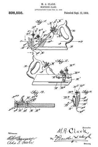
I illustrate my invention in the accompanying drawings, in which:–

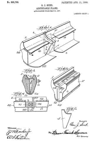
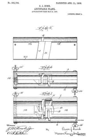
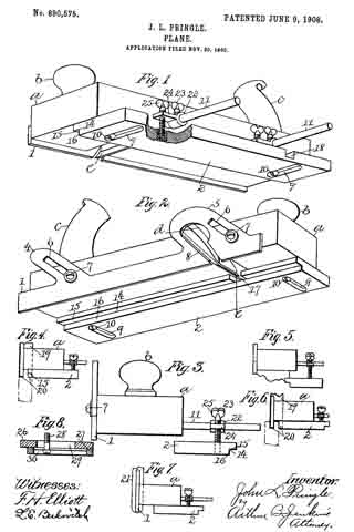
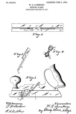
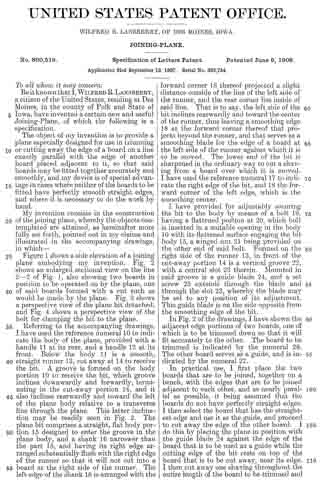
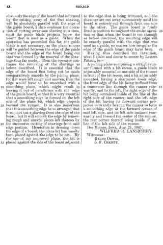
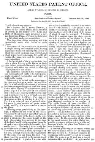
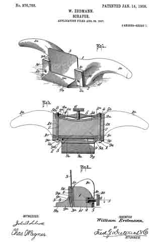
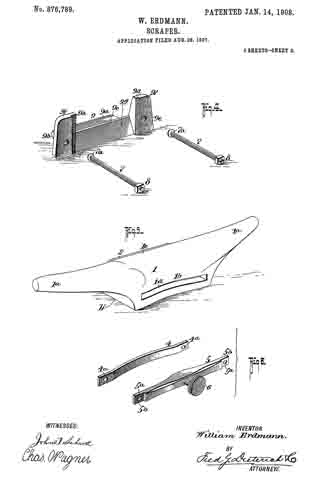
Figure 1 is a side elevation of the plane, parts being shown in section. Fig. 2 is a side elevation, Fig. 3 is a cross sectional view and Fig. 4 is a sectional view taken on line 4–4 of Fig. 1.

Reference now being had to the details of the drawings by letter, A designates a stock of the plane, made preferably of metal, and has an integral handle B at one end thereof. Said stock has a vertically formed slot D’ therein for the reception of the cutting blades F, details in edge view of which are shown in Fig. 4 of the drawings. It will be noted upon reference to said blades F, that each of said blades is beveled and is designed to cut two slots spaced apart and parallel to each other. Said blades are mounted upon a screw D3 which passes through the arms of the bracket extension D4, as shown in Fig. 4 of the drawings, and D5 is a wheel with a milled edge and having a threaded aperture to engage the ends of said screws D3 whereby as the screw is raised and lowered, the depth at which it may be desired to have the blades cut, may be regulated. In order to hold the blades securely, a tapering pin F2 is provided passing through a similar shaped transverse aperture, as shown in Fig. 3 of the drawings the marginal edge of said pin being adapted to be drawn against the edges of the two blades F by means of a thumb nut F3 upon a tmeaded end of said pin.

H designates a wedged block which is mounted in a vertical slot in the stock and H’ designates a pin which is fastened to said wedged block and extends through the bracket arms H2 similar in construction to the bracket arms shown in Fig. 4 of the drawings and H3 is a wheel having a threaded opening for engagement with the screw H’, whereby said block may be raised or lowered.

It will be noted that the block H cooperates with the tapering pin F2 for the purpose of frictionally holding the blades in adjusted positions.

K designates a knife which is mounted in a diagonally disposed slot D2 formed in the stock and E designates a pin which is tapered, provided with a threaded end E2 upon which a thumb nut E3 is mounted, said pin E passing through a tapering aperture in the stock plane.

H4 designates a set screw mounted in a threaded aperture in the stock and adapted to bear against the pin E to hold the same in an adjusted position. A suitable screw N2 is fixed to the knife K, said screw not passing through the bracket arms N3 of the stock and N is a wheel having a threaded aperture to iit the screw end N’ and provided with a milled circumference.

R designates a gage having an integral rod R’ projecting therefrom and extending through an aperture in a projecting portion R2 of the stock, which projecting portion carries a set screw R3 for engagement with the rod R’ to hold the same m an adjusted position. The upper end of said rod R’ is threaded to receive an adjusting wheel R4 with a milled edge, and R5 designates a projection upon said wheel R4 which is swiveled in a recess in said projection R2.

In operation, the cutting blades F being adjusted with their cutting ends projecting below the bottom of the plane, the apparatus is positioned over the surface to be cut, the two blades F cutting the marginal edges of the groove while the planer or plowing blade K follows on and mortises out the parts intermediate the side walls of the groove. Owing to the adjustment of the gage R upon the stock, it will be noted that the depth at which it may be desired to mortise may be readily adjusted by simply loosening the set screws and raising or lowering the gage R after which the screws may be tightened and the apparatus held in its adjusted position.

by the provision of a mortising plane as shown and described, it will be observed that means is afforded whereby a groove or channel may be readily formed without inconvenience, even though the rnortising to be done may be in positions ordinarily inaccessible by means of the usual planes provided for the purpose and so arranged that the blades may be readily adjusted for mortising at different depths.

What I claim is :–

1. A mortising plane comprising a stock having a vertical slot in the forward end thereof, an inclined planer blade, blades mounted in said slot with their inner faces in contact with each other, a pin passing through a ertures in said blade, a screw to which said pin is secured, a bracket arm rising from the stock and having laterally extending fingers which are spaced apart and provided with apertures, a wheel mounted between said fingers and provided with a central threaded aperture through which said screw passes, a wedge block mounted in said slot and bearing against corresponding edges of said blades, means for moving said block, a screw having an unthreaded tapering portion passing through the stock and adapted to bear against the edges of said blades opposite said wedge block, and a nut upon said blade engaging stock, as set forth.

2. A mortising plane comprising a stock having a vertical slot in the forward end thereof, an inclined planer blade, blades mounted in said slot with their inner faces in contact with each other, a pin passing through apertures in said blade, a screw to which said pin is secured, a bracket arm rising from the stock and having laterally extending fingers which are spaced apart and provided with apertures, a wheel mounted etween said fingers and provided with a central threaded aperture through which said screw passes, a wedge block mounted in said slot and bearing against corresponding edges of said blades, a second bracket arm rising from the stock and having laterally projecting fingers which are spaced apart, a screw fastened to the block and passing through the apertures in the adjacent fingers, means for raising and lowering the stock connected to the block, and a screw passing through a transverse aperture in the stock and provided with an unthreaded tapering portion bearing against the edges of said blades, as set forth.

In testimony whereof I hereunto affix my signature in the presence of two witnesses.

MAURICE A. CLARK.

Witnesses:
HENRY GILBERT,
WILLIAM CHARLES CUNNINGHAM.

No. 895,796 – Adjustable Plane (Owen J. Sund) (1908)

[paiddownloads id=”656″]895796


UNITED STATES PATENT OFFICE.

_________________

OWEN J. SUND, OF TACOMA, WASHINGTON.

ADJUSTABLE PLANE.

_________________

895,796. Specification of Letters Patent. Patented Aug. 11, 1908.
Application filed May 16, 1907. Serial No. 373,931.

_________________

To all whom it may concern:

Be it known that I, OWEN J. SUND, a citizen of the United States, residing at Tacoma, in the county of Pierce and State of Washington, have invented certain new and useful Improvements in Adjustable Planes; and I do hereby declare the following to be a full, clear, and exact description of the invention, such as will enable others skilled in the art to which it appertains to make and use the same.

This invention relates to improvements in planes and particularly to adjustable planes of the type known as “carpenter’s nosing planes.”

The invention comprises the production of a cutter-holder and means for varying the width at which the same is designed to operate.

The invention further comprises the production of a plurality of cutter-holders that are designed to register with each other for providing means for varying the width of cut of the cutters.

The invention still further comprises the production of a plurality of cutter-holders designed to be adjustably secured together, and means for varying the adjustment, for regulating the width of cut desired.

The object in view is the production of a plane for forming rounded edges that may be adjusted to any desired width and without changing the cutting tools used.

A still further object of the invention is the production of a nosing plane formed in a plurality of parts, and means for adjustably securing same together, and cutters that are designed to extend past each other, in order to form a cutting surface of varying width.

With these and other objects in view, the invention comprises certain other novel constructions, combinations and arrangements of parts as will be hereinafter more fully described and claimed.

In the accompanying drawing:–Flgure 1 is a perspective view of one of the cutter-holders and surrounding parts. Fig. 2 is a side elevation of a cutter forming part of the present invention. Fig. 3 is a cross-section through a plane constructed according to the present invention the section being taken on the line 3–3 of Fig. 1. Fig. 4 is a detail fragmentary bottom plan view of a plane formed according to the present invention, an adjusting device being seen in connection therewith. Fig. 5 is a side elevation of one of the cutter-holding members. Fig. 6 is a bottom plan view of a plane formed according to the present invention the cutters being removed. Fig. 7 is a bottom plan view of a plane the cutters being removed, said plane being adjusted to its extreme position, certain parts being broken away to better disclose the invention. Fig. 3 is a detail fragmentary perspective view of a slightly modified form of the present invention.

In constructing a plane according to the present invention, I provide a pair of cutter-holding members 1 and 2. Member 1 has formed integral therewith an extension 3, as clearly seen in Fig. 1, for accommodating a slot 4, which is designed to extend from the outer edge of member 3 to the outer edge of member 1. Slot 4 is designed to be of such a shape and depth as to accommodate cutter 5. An adjusting screw or clamping member 6 is screw-threaded into member 3 and is designed to extend entirely through one of the walls of the same and engage cutter 5 for holding the same in position for having its cutting edge 7 project a short distance above the surface of the members 1 and 2. Member 2 is made similar to member 1 and has provided an extension 3 similar to extension 3 which is designed to accommodate a slot 9 similar to slot 4 in which a knife, as 5, is designed to be inserted and held in place by a suitable clamping member 10. Member 8 is designed to fit into a hollowed-out portion 11 in member 1 and member 3 is designed to iit into a hollowed-out portion 12 of member 2, when members 1 and 2 are in their closed position, as seen in Fig. 1, or when in a partially closed position. When in a closed position a semi-circular portion 13 is formed between members 1 and 2, as clearly seen in Fig. 3 for forming a rounded edge upon any board or other device that is designed to have the edges rounded. As seen in Fig. 3 the curved portion 13 is semi-circular in cross-section and the plane will cut or round the edge of any board or material to which the same is applied. If the material requires it the curved part 13 members 1 and 2 may be moved apart by unscrewing thumb screws 14 and 15. When thumb screws 14 and 15 are screwed outward, springs 16 will force outward member 22 to any desired distance, as, for instance, seen in Fig. 7. Though the members 1 and 2 are thus forced apart, a cutting surface is provided for the space between the same, as cutting members 5, located in slots 4 and 9, pass each other, as clearly seen in Fig. 7, for providing a continuous cutting edge regardless of the distance apart of members 1 and 2. By this construction one set of knives, as 5, will cut or round the edges of boards, planks, and the like, of various widths or thicknesses, without changing the cutting knife. In order to form a bottom or surface for taking place of the surface 13, when members 1 and 2 are moved apart, I provide sliding members 18 and 19, which are accommodated in slots 20 and 21.

Positioned on the opposite side or bottom to the cut out portion or depression 13 are members 22 and 23, which are designed to overlap and form a support for the hands of the operator, when using the plane, so that the operator will not be under any danger of accidentally placing his hand between members 1 and 2 during the operation of the device. Members 22 and 23 also form a smooth, even surface, against which the hands of the operator may press when using the plane.

When moving members 1 and 2 from the position shown in Fig. 6, thumb screws 14 and 15 are unscrewed or moved outward, and springs 16 normally force outward the members against which the same are designed to press, but in order to form a more positive operation of forcing apart and holding in the extended position, I provide adjusting member 24. Adjusting member 24 is preferably placed upon the top of the plane and is composed of reciprocating members 25 and 26 that are secured to members 1 and 2, respectively. Members 25 and 26 are provided on one edge with a rack bar for engaging a gear wheel 27, which is designed to be revolved by a suitable hand wheel 28. When springs 16 fail to work and when it is desired to positively hold in an extended position members 1 and 2, hand wheel 28 is revolved, and in turn forces outward members 25 and 26, which are secured respectively to members 1 and 2.

In constructing a device according to the present invention, slots 4 and 9 may be made at any desired angle for accomplishing the desired result, and members 1 and 2 may be made of any desired material, but are preflerably made from a good quality of steel.

Referring more particularly to Fig. 8, it will be observed that I form the same in a slightly modified way the way I form members 1 and 2 of the preferred construction. Members 1′ and 2′ are formed with projections 29 and 30 on the inner surface, which are designed to fit into slots or depressions 31 and 32. This is designed to take the place of members 18 and 19 and for guiding members 1′ and 2′ in their movement and to form a sort of false bottom. Suitable overlapping members 22′ and 23′ are used on the back of the plane, similar to the members 22 and 23.

What I claim is:

1. In a plane, a plurality of cutting-holders overlapping, cutters adjustably secured therein, their cutting edges adjoining each other and arranged in parallel lanes and means for varying the position of the cutter holders.

2. A plane, comprising a plurality of cutter-holders overlapping, cutters positioned therein their cutting edges adjoining each other and arranged in parallel planes, means for varying the position of said cutter-holders, and means for guiding said cutter-holders in their various positions.

3. A plane, com rising a plurality of cutter-holders, formed with a cut out portion and a projection, the projection of one cutter-holder being adapted to register with the cut out portion of the corresponding cutter-holder, overlapping cutters positioned therein, their cutting edges adjoining each other and arranged in parallel planes and means for holding said cutter-hollders in operative position.

4. A plane, comprising a plurality of cutter-holders, said cutter-holders being formed with a cut out portion and a projecting portion, the projecting portion of one cutter-holder being adapted to register with the cut out portion of the other cutter-holder, said cutter-holders being formed with slots that extend into said projections, overlapping cutters positioned therein, their cutting edges adjoining each other and arranged in parallel planes, and means for adjusting the cutter-holders to various positions for varying the cut of said cutters.

5. A plane comprising a plurality of transverse cutter holders formed with overlapping portions, overlapping cutters positioned therein, the edges of said cutters being arc-shaped, and means for forcing apart said cutter holders in planes parallel with each other for varying the widlfh of the cut, the shape of the cutters permitting the separation of the same without changing the shape of the cut.

6. A plane, comprising a plurality of cutter-holders, overlapping cutters positioned therein, their cutting edges adjoining each other and arranged in parallel planes, and means for forcing apart said cutters, said means comprising a plurality of rack bars, a gear wheel for operating said rack bars, a hand wheel for operating said gear wheel, and means for holding said gear wheel in contact with said rack bars.

7. A plane, comprising a plurality of cutter-holders, overlapping cutters mounted therein, their cutting edges adjoining each other and arranged in parallel planes, a set screw for holding the same in any desired position, and means for regulating the distance between said cutter-holding members.

8. A plane, comprising a plurality of cutter-holders, overlapping cutters positioned in said holders the edges of said cutters being segment shaped, means for varying the distance between said cutter-holding members, and longitudinal overlapping strips secured to said cutter-holding members on the edges opposite the cutting edges.

In testimony whereof I affix iny signature in presence of two witnesses.

OWEN J. SUND.

R. D. SHUTT,
W. G. HEINLY.

No. 890,575 – Plane (John L. Pringle) (1908)

[paiddownloads id=”655″]890575


UNITED STATES PATENT OFFICE.

_________________

JOHN L. PRINGLE, OF NEW BRITAIN, CONNECTICUT.

PLANE.

_________________

890,575. Specification of Letters Patent. Patented Jun. 9, 1908.
Application filed November 20, 1905. Serial No. 288,128.

_________________

To all whom it may concern:

Be it known that I, JOHN L. PRINGLE, a subject of the King of Great Britain, and residing at New Britain, in the county of Hartford and State of Connecticut, have invented a new and Improved Plane, of which the following is a specification.

My improvement relates to the class of hand tools used for working upon the surface of boards and the like for smoothing or for grooving, or for similar purposes, and the object of my invention is to provide a plane which shall be simple and cheap in construction, few as to the number of parts, and one which may be put to all of the varied uses to which this class of devices are subjected.

One form of device in the use of which the desired object may be attained is illustrated in the accompanying drawings, in which —

Figure 1 is a perspective view illustrating the bottom and one side of a plane embodying my invention. Fig. 2 is a like view looking from the opposite side of the plane. Fig. 3 is an end view showing the bottom gage-sole used as a side gage. Fig. 4 is what may be termed an illustrative view showing the application of my improvement in cutting a tongue on the edge of a board. Fig. 5 is a like view showing the improvement adapted to the formation of a molding. Fig. 6 is a like view showing the improved tool adapted to cut a groove in the edge of a board. Fig. 7 is a like view showing the improved tool as applied to cutting a concaved surface. Fig. 8 is a view illustrating a modified form of the adjustable gage-sole.

In the accompanying drawings the letter a denotes the body or stock of tlie plane, b a knob or handheld at the forward end, and c a handle located at or near the rear end and on the upper surface of the body part in the usual manner. The body part may be constructed of wood or of any other desired material common to tools of this class. The body part is also provided with a depthwise opening d in which the blade or bit e is located. All of these parts may be of any ordinary and well-known construction.

In carrying out my invention I provide a vertically adjustable secondary sole 1 secured preferably to the side part of the body of the plane, and a laterally adjustable gage-sole 2 which is located underneath the body. The sole 1 includes a plate extendin lengthwise of the body part of the plane, this plate being of proper width and thickness for the purposes in hand, and as shown herein, and as ears 4–5 projecting from the upper edge thereof. These ears are provided with slots 6 through which adjusting studs or screws 7 extend for the purpose of holding the plate in any position of vertical adjustment. An opening 8 is also formed through the ear 5 through which cutting tools or blades of various form may project.

The gage-sole 2 has slots 9 extending laterally thereof formed therein, and studs or screws 10 projecting through these slots into the body of the plane serve as a means of securing the shoe in any position of lateral adjustment. The heads of the screws 10 are located well within the slots, the latter being shouldered to receive the head of the screw. These slots 9 are located at equal distances from the ends of the sole so that the latter may be reversed end for end for certain purposes to be hereinafter described.

It will be seen from the above description and the accompanying illustration that by removing the soles 1 and 2 the plane may be used for all the purposes of a smoothing plane or other surfaces. By placing the secondary sole 1 in position and providing the proper cutting blade the plane may serve the purpose of a plow. By placing the gage-sole 2 and adjusting it in proper position laterally on the bottom of the body part with a proper shaped blade in position, the plane may be used to out moldings of different form. By properly adjusting the soles 1 and 2 with respect to each other and using a blade of proper form articles may be formed of curved shape or round.

The gage-sole 2 is provided on one edge with a recess 14 the walls of which are located preferably at right-angles to each other. When this groove is employed what may be termed the horizontally arranged wall 15 will serve as the bottom proper or sole of the plane, in connection, of course, with the secondary sole 1, and the side or vertically arranged wall 16 will form a gage.

The gage-sole 2 is provided with blade recesses 17 and 18. These recesses are formed to receive one side of the blade of a bit when the tool is used for certain purposes. As shown in Fig. 2, the recess 17 covers one side of the cutting edge of a comparatively wide bit, so that the pidane with such bit may be used as a fillister plane.

By adjusting the gage-sole 2 vertically and laterally, as shown in Fig. 5 of the drawings, and also by adjusting the second ary sole 1 it will be seen that the plane is readily adapted for cutting various forms of moldings, the blade 18 being, of course, properly adjusted.

By adjusting the parts as shown in Fig. 4 the device is adapted for cutting a tongue on the edge of a board, the bit 19 having one of the prongs lying within the opening 8 in the vertical guide, and the other prong extending through the shoulder 15, the edges of these being shown projecting as at 20 in Fig. 4. By reversing the gage-sole 2 and moving it to the position shown in Fig. 6 the device may be used for cutting a groove on the edge of a board, the same knife as shown in Fig. 4 being employed, and that point located within the opening in the secondary sole 1 cutting the groove and the other point being located within the recess 18 in the sole 2, as shown in dotted outline in Fig. 6.

If a circular or curved recess is to be reduced then a blade 21, as shown in Fig. 7 of the drawings, may be used, having its cutting edge of proper form, the extreme curved edge of the blade being located just in advance of the sole 1, and the sole 2 being emlployed as a guide.

In order to adapt the sole 2 for vertical adjustment adjusting supports are mounted on the arms 11, these consisting of a sleeve 22 having set screws 23 with wings 24 bearing adjusting screws 25 which engage threaded sockets in the surface of the gage-sole 2. When the gage-sole 2 is used with the recess 14 facing the secondary sole 1, as shown in Figs. 1, 2, 4, and 5 of the drawings, the screws 10 may be turned out of the stock a or may be removed entirely. It is also obvious that when the gage-sole 2 is used as shown in Figs. 1 and 2, the adjusting screws 25 are not absolutely essential, a though they form a means of support for the projecting edge of the sole.

While the secondary sole 1 has been shown herein as adjustable it is obvious that advantageous results would follow its use in a plane in which it was rigidly secured to the stock without any means of adjustment, but by providing the adjustment I secure all of the advantages present in the late as used in either of the ways mentioned.

In the form of adjustable sole shown in Figs. 1 and 2 the gage-sole is reversed end for end when it is desired to employ the sole as a gage. In Fig. 8 I have adapted this form of the invention so that the sole need not be so reversed when it is to be employed as a gage. In this form of the invention I construct the gage-sole in two parts, a main section 26 and an adjustable section 27. The main section is rovided with a groove 29, and the adjustable section with a shouldered groove 30, a screw 28 to take the place of the screws 10 hereinbefore described for holding the parts in engagement and for holding the sole as a whole in place on the sole or bottom of the plane. It will be seen from this construction that with the parts adjusted as shown in Fig. 8 the device is applicable for the same use as shown in Figs. 1 and 2. By loosening the screw and moving the adjustable section 27 so that the edges are flush, then the sole is adapted for a gage, as illustrated in Fig. 3. It will be noted that the parts 1 and 2 act as soles for the plane, that is, they support the plane in a direction depthwise thereof, the secondary sole 1 supporting the plane when grooves, tongues and the like are being cut, and the gage-sole in connection with the secondary sole supporting the plane as when moldings, and rabbets are cut. It will be noted that when either of the soles 1 and 2 are employed the sole proper of the plane is not in use, the latter mainly being employed when the plane is used as an ordinary surface plane.

I claim:

1. A stock having a bit opening and adapted for use as a surface plane, a secondary sole secured to the side surface of said stock and adjustable depthwise to project below the main sole thereof, and a gage-sole underlying said main sole and adjustable laterally thereof, both of said secondary and gage-soles having openings for the bit and adapted to cooperate therewith in the cutting operation.

2. A stock having a bit opening and adapted for use as a surface plane, a secondary sole secured to the side surface of said stock and adjustable depthwise to project below the sole thereof, a age-sole underlying the main sole and lateragy adjustable thereof, and means for securing the latter sole directly to the under surface of the stock, both of said secondary and gage-soles having openings for a bit to cooperate therewith in the cutting operation.

3. A stock having a bit opening adapted for use as a surface plane, a secondar sole secured to the side surface of the stock and adjustable depthwise to project below the main sole thereof, a reversible gage-sole underlying the said main sole, means for securing said sole in position, both of said secondary and gage-soles having bit openings to cooperate with the bit in the cutting operation.

4. A stock having a bit opening and adapted for use as a surface plane, a secondary sole secured to the side surface of the stock and adjustable depthwise to project below the main sole thereof, a reversible gage-sole underderlying said main sole and adjustable laterally thereof, means for securing said gage-sole directly to the bottom of the stock, both of said secondary and gage-soles having openings for a bit to cooperate therewith in the cutting operation.

5. A stock having a bit opening and adapted for use as a surface plane, a secondary sole secured to the side surface of the stock and adjustable depthwise thereof to project below its main sole, a gage-sole underlying the stock and adjustable vertically and laterally thereof, and means for adjustably securing said gage-sole directly to the under surface of the stock, both of said secondary and main soles having bit openings to cooperate therewith in the cutting operation.

6. A stock having a bit opening, and adapted for use as a surface plane, a secondary sole secured to the side surface thereof and adjustable depthwise to project below its main sole, a gage-sole underlying the stock and vertically and laterally adjustable thereof, means for adjustably securing said sole directly to the under surface of the stock and including slots for the reception of screws and recesses for the reception of the heads thereof, screws for securing said soles, each of said secondary and main soles having openings for a bit to cooperate therewith in the cutting operation.

7. A stock having a bit opening and adapted for use as a surface plane, a secondary sole secured directly to the side surface and adjustable deipthvvise to project below the main sole thereo, a reversible gage-sole underlying the stock and adjustable vertically and laterally thereof, and means for securing said sole directly to the main sole of the stock, both of said secondary and main soles having openings for the bit to cooperate therewith in the cutting operation.

8. A stock having a bit opening and adapted for use as a surface plane, a secondary sole secured to the side surface of the stock and adjustable depthwise to project below the main sole thereof, a gage-sole underlying the stock and reversible thereon and vertically and laterally adjustable thereof , slots in said sole for the reception of screws and recesses for the heads thereof, and screws for securing said sole directly to said main sole, both of said secondary and main soles having openings for a bit to cooperate therewith in the cutting operation.

JOHN L. PRINGLE.

Witnesses:
ARTHUR B. JENKINS,
LENA E. BERKOVITCH.

No. 890,519 – Joining-Plane (Wilfred R. Lansberry) (1908)

[paiddownloads id=”654″]890519


UNITED STATES PATENT OFFICE.

_________________

WILFRED R. LANSBERRY, OF DES MOINES, IOWA.

JOINING-PLANE.

_________________

890,519. Specification of Letters Patent. Patented June 9, 1908.
Application filed September 19, 1907. Serial No. 393,734.

_________________

To all whom it may concern:

Be it known that I, WILFRED R. LANSBERRY, a citizen of the United States, residing at Des Moines, in the county of Polk and State of lowa, have invented a certain new and useful Joining-Plane, of which the following is a specification.

The object of my invention is to provide a plane especially designed for use in trimming or cutting away the edge of a board on a line exactly parallel with the edge of another board placed adjacent to it, so that said boards may be fitted together accurately and smoothly, and my device is of special advantage in cases where neither of the boards to be fitted have perfectly smooth straight edges, and where it is necessary to do the work by hand.

My invention consists in the construction of the joining plane, whereby the objects contemplated are attained, as hereinafter more fully set forth, pointed out in my claims and illustrated in the accompanying drawings, in which —

Figure 1 shows a side elevation of a joining plane embodying my invention. Fig. 2 shows an enlarged sectional view on the line 2–2 of Fig. 1, also showing two boards in position to be operated on by the plane, one of said boards formed with a cut such as would be made by the plane. Fig. 3 shows a perspective view of the plane bit detached, and Fig. 4 shows a perspective view of the bolt for clamping the bit to the plane.

Referring to the accompanying drawings, I have used the reference numeral 10 to indicate the body of the plane, provided with a handle 11 at its rear, and a handle 12 at its front. Below the body 11 is a smooth, straight runner 13, cut away at 14 to receive the bit. A groove is formed on the body portion 10 to receive the bit, which groove inclines downwardly and forwardly, terminating in the cut-away portion 14, and it also inclines rearwardly and toward the left of the plane body relative to a transverse line through the plane. This latter inclination may be readily seen in Fig. 2. The plane bit comprises a straight, flat body portion 15 designed to enter the groove in the plane body, and a shank 16 narrower than the part 15, and having its right edge arranged substantially flush with the right edge of the runner so that it will not cut into a board at the right side of the runner. The left edge ofthe shank 16 is arranged with the forward corner 18 thereof projected a slight distance outside of the line of the left side of the runner, and the rear corner lies inside of said line. That is to say, the left side of the bit inclines rearwardly and toward the center of the runner, thus leaving a smoothing edge 18 at the forward corner thereof that projects beyond the runner, and that serves as a smoothing blade for the edge of a board at the left side of the runner against which it is to be moved. The lower end of the bit is sharpened in the ordinary way to cut a shaving from a board over which it is moved. I have used the reference numeral 17 to indicate the right edge of the bit, and 18 the forward corner of the left edge, which is the smoothing center.

I have provided for adjustably securing the bit to the body by means of a bolt 19, having a flattened portion at 20, which bolt is inserted in a suitable opening in the body 10 with its flattened surface engaging the bit body 15, a winged nut 21 being provided on the other end of said bolt. Formed on the right side of the runner 13, in front of the cut-away portion 14 is a vertical groove 22, with a central slot 23 therein. Mounted in said groove is a guide blade 24, and a set screw 25 extends through the blade and through the slot 23, whereby the blade may be set to any position of its adjustment. This guide blade is on the side opposite from the smoothing edge of the bit.

In Fig. 2 of the drawings, I h ave shown the adjacent edge portions of two boards, one of which is to be trimmed down so that it will fit accurately to the other. The board to be trimmed is indicated by the numeral 26. The other board serves as a guide, and is indicated by the numeral 27.

In practical use, I first place the two boards that are to be joined, together on a bench, with the edges that are to be joined adjacent to each other, and as nearly parallel as possible, it being assumed that the boards do not have perfectly straight edges. I then select the board that has the straightest edge and use it as the guide, and proceed to cut away the edge of the other board. I do this by placing the plane in position with the guide blade 24 against the edge of the board that is to be used as a guide while the cutting edge of the bit rests on top of the board that is to be cut away, near its edge. I then cut away one shaving throughout the entire length of the board to be trimmed and obviously the edge of the board that is formed by the cutting away of the first shaving, will be absolutely parallel with the edge of the guide board, I then continue the operation of cutting away one shaving at a time, until the guide blade projects below the board that is used as a guide. When the operation has proceeded. this far, the guide blade is not necessary, as the plane runner will be guided between the edge of the guide board and the edge of the board being cut that was formed by the removal of the shavings thus far made. Then the operator continues the removing of the shavings as before described. It is essential that the edge of the board first being cut be made comparatively smooth by the joining plane, for if it were left rough and uneven, then the edge would have to be smoothed with a smoothing plane, which might result in leaving it out of parallelism with the edge of the guide board, so that it is very essential that a smoothing edge be formed on the left side of the plane bit, which edge projects beyond the runner. It is also important that this smoothing edge be so arranged that it will not cut a shaving from the edge of the board, but it will smooth the edge by removing rough and uneven pieces left thereon by the successive cutting of shavings from said edge portion. Heretofore in dressing down the edge of a board, the plane bit has usually been placed against the edge to be cut. By the use of my improved plane, the bit is placed against the side of the board adjacent to the edge that is being trimmed, and the shavings are cut away successively until the board is entirely cut through from one side to the other. The guide board is firmly fixed in position throughout the entire operation so that when the board is cut through as before described, the resulting edge will be exactly parallel with the edge that was used as a guide, no matter how irregular the edge of the guide board may have been.

Having thus described my invention, what I claim and desire to secure by Letters Patent, is —

A joining plane comprising a straight runner formed with a bit recess, a guide blade adjustably mounted on one side of the runner in front of the bit recess, and abit adjustably mounted, having a sharpened lower edge, the front edge of the bit being inclined from a transverse line through the runner rearwardly, and to the left, the right edge of the bit being contained inside of the line of the right side of the runner, and the left edge of the bit having its forward corner projected outwardly beyond the runner to form a smoothing edge at the forward corner of said left side, and its left side inclined rearwardly and toward the center of the runner, the rear corner thereof being inside of the line of the left side of the runner.

Des Moines, Iowa, Aug. 21, 1907.

WILFRED R. LANSBERRY.

Witnesses:
RALPH ORWIG,
S. F. CHRISTY.

No. 879,793 – Plane (Andro Nyland) (1908)

[paiddownloads id=”653″]879793


UNITED STATES PATENT OFFICE.

_________________

ANDRO NYLUND, OF DULUTH, MINNESOTA.

PLANE.

_________________

879,793. Specification of Letters Patent. Patented Feb. 18, 1908.
Application filed May 28, 1907. Serial No. 376,047.

_________________

To all whom it may concern:

Be it known that I, ANDRO NYLUND, a citizen of the United States, and a resident of Duluth, in the county of St. Louis and State of Minnesota, have invented a new and Improved Plane, of which the following is a full, clear, and exact description.

This invention relates to planes, and it is particularly useful with rabbet or dado planes.

The object of the invention is to provide a simple, strong and efficient plane, having adjustable means for limiting the depth to which the cut of the plane may proceed, and which is provided with means for easily adjusting the plane iron and for locking the same in position.

A further object of the invention is to provide a plane having guide blades at both sides thereof, which can be easily and quickly adjusted, and which has means for limiting the projection of the blades.

The invention consists in the construction and combination of parts to be more particularly described hereinafter and fully set forth in the claims.

Reference is to be had to the accompanying drawings forming a part of this specification, in which similar characters of reference indicate corresponding parts in all the views, and in which Figure 1 is a side elevation of the plane; Fig. 2 is an elevation of the opposite side of the plane, showing parts broken away and in section 5 Fig. 3 is a vertical cross-section on the line 3–3 of Fig. 1; Fig. 4 is a vertical cross-section on the line 4–4 of Fig. 1; Fig. 5 is an enlarged view of a detail showing parts in cross section and parts broken away; and Fig. 6 is a plan view of a part of the plane.

Referring more particularly to the drawings, 1 represents the body of the plane, which may be of wood or any other suitable material. Secured to the body 1 is the sole-plate 2 extending the entire length of the tool. Side-plates 3 are secured to the sides of the body, and like the sole-plate 2 may be of steel or any other suitable material, preferably metal. The body 1 is cut away between the sides to form a plane iron recess 4. The recess 4 presents a flared opening 4a at the side, through which the shaving formed by the plane iron can leave the tool. The plane iron 5 is mounted in the recess 4 and presents a rack 6. A pinion 7 in mesh with the rack 6 is rotatably mounted in an extension 8 of the recess 4. The pinion 7 has a shank 9 extending through the side of the plate and provided with a wing 10, by means of which it may be operated. A locking-block 12 is secured upon the plane iron on the side opposite to the pinion 7. A set-screw 13 is mounted in a suitably threaded opening of the body and abuts against the block 12. The set-screw 13 is provided with a- wing 14 by means of which it may be operated to jam the plane iron in position through the block 12, which is carried in the recess 4 upon transverse pins 15 arranged in openings 16 of the block.

A recess 17 is formed in the body between the side plates 3, and connects with lateral guide grooves 18 formed at the sides of the body by the side-plates 3 which are cut away for this purpose. A threaded member 19 is arranged slidably in the recess 17 and is engaged by a screw pin 20. The screw pin 20 has a collar 21 seating against the upper part of the body, and a nut 22 in engagement with the inner wall of the recess to prevent the displacement of the screw pin, which has at its outer extremity a wing 23 by means of which it may be manually operated to adjust the member 19 within the recess. It will be understood that as the screw pin 20 is turned the member will move up or down within the recess. Guide blades 24 are slidably mounted in the guide grooves 18 and have slots 25. The guide blades 24 are adjustably secured to the member 19 by means of screws 26 arranged in the slots 25 and secured in suitable threaded openings in the member 19. The guide blades 24 have shoulders 27 adapted to engage with shoulders 28 formed at an edge of each slot, to limit the projection of the cutting point 29 of the blade from the groove. The guide blades are adapted to be projected a distance beyond the sole of the plane, equal at least to the projection of the plane eyes. In the operation of the plane in the usual manner, the guide blades form parallel grooves or guides exactly within and between which the plane iron follows and cuts the shaving.

A vertical guide-way 30 is formed within the body and has a lateral slot 31 extending through the side 3. A slidable member 32 comprising substantially a rod, is arranged within the guide-way 30 and has a lateral extension 33 in the slot 31. A gage member is secured to the extension 33 by means of a screw 35. The gage member 34 has a supplemental sole 36. The gage member may be adjusted at the side of the body by moving the member 32 up or down within the guide-way. A transverse pin 37 is arranged adjacent to the member 32 and has a wing 33 at the side, by means of which it may be operated. An eccentric cam groove 39 is formed in the pin 37. When the member 32 engages the cam groove at the greatest depth of the same the member is free to slide within the guide-way. When the pin 37 is rotated from this position the member 32 is jammed within the guide-way by the cam-like action of the groove. The pin 37 is provided with a second annular groove 40 with which a pin 41 carried by the body engages to prevent the lateral displacement of the adjusting pin 37. Aleaf spring 47 is arranged in the guide-way 30 and engages the member 32 to hold the same resiliently within the guide-way and to prevent lateral movement of the same. The gage 34 serves to determine and measure the depth oi the rabbet formed by the plane. A guide-plate 42 having slots 43 is adjustably mounted at the side of the plane opposite to the gage 34, by means of set-screws 44 arranged in the slots 43 and in suitable openings of the body. The guide-plate 42 extends the entire length of the plane and is adapted to be projected below the sole of the same to guide the tool at the edge of the work when a rabbet is being cut. A handle 45 is mounted by means of screws 46 at one side of the plane and serves for holding the tool when it is in operation.

Having thus described my invention I claim as new, and desire to secure by Letters Patent:

1. In a plane, a plane iron having a rack, and a pinion adapted to be manually controlled and operatively engaging with said rack, a block tapered toward the cutting edge of said iron and loosely mounted to engage the same, and a set screw adjustably engaging said block to lock said iron in position.

2. In a plane, a body having a guide-groove, a guide-blade mounted to slide in said groove, a movable member arranged to slide in the longitudinal direction of said groove and having an adjustable connection with said blade, and means for adjusting said member.

3. In a plane, a body having a recess, and a guide-groove communicating with said recess, a movable member in said recess, a guide-blade in said groove and having an adjustable connection with said member, and a screw-pin engaging with said member and controlling the same.

4. In a plane, a body having a recess, and a guide-groove communicating with said recess and presenting a shoulder, a movable member in said recess, a guide-blade in said groove and having an adjustable connection with said member, said guide-blade presenting a shoulder adapted to engage said shoulder of said guide-groove to limit the projection of said blade from said groove, and a screw-pin engaging with said member and controlling the same.

5. In a plane, a body having a recess and guide-grooves at opposite sides of said body and communicating with said recess, a movable member in said recess, guide-blades in said grooves and presenting slots, adjustable screws carried by said member and engaging said slots to secure said blades to said member, and a screw-pin operatively engaging said member and having collars engaging said body to prevent the longitudinal movement of said pin.

In testimony whereof I have signed my name to this specification in the presence of two subscribing witnesses.

ANDRO NYLUND.

Witnesses:
S. C. MILLER,
W. A. ANDERSON.

No. 876,789 – Scraper (William Erdmann) (1908)

[paiddownloads id=”652″]876789


UNITED STATES PATENT OFFICE.

_________________

WILLIAM ERDMANN, OF MADISON, WISCONSIN.

SCRAPER.

_________________

876,789. Specification of Letters Patent. Patented Jan. 14, 1908.
Application filed August 28, 1907. Serial No. 390,520.

_________________

To all whom it may concern:

Be it known that I, WILLIAM ERDMANN, residing at Madison, in the county of Dane and State of Wisconsin, have invented a new and Improved Scraper, of which the following is a specification.

My invention relates to certain new and useful improvernents in scrapers for dressing floors and the like, and the invention primarily has for its object to provide a scraper of an improved construction which can be easily and cheaply manufactured and which will readily and effectively serve its intended purposes. In my invention means are provided for holding and clamping the scraping blade, which means can be easily and quickly adjusted to permit insertion or withdrawal of the blade, as the case may be.

Another object of my invention is to provide a scraper having a yielding pad against which the blade rests to absorb or prevent vibration when the implement is in use.

The invention also embodies certain novel construction, combination and arrangement of parts, all of which will be first described in detail and then be specifically pointed out in the appended claims, reference being had to the accompanying drawings, in which, —

Figure 1, is a perspective view of my invention. Fig. 2, is a central, vertical section thereof. Fig. 3, is a horizontal section on the line 3–3 of Fig. 2. Fig. 4, is a perspective view of the metallic gage and blade holding clamp member. Fig. 5, is a similar view of the stock and handle member. Fig. 6, is a perspective view of the bridge members.

Referring now to the accompanying drawings in which like letters and numerals of reference indicate like parts in all of the figures, 1 designates the stock with which the handles 1a merge, and the stock 1 has its under face plane, while its front face 1c is in a plane held at an obtuse angle to the plane containing the horizontal surfaces 1b of the stock.

Cemented or otherwise held in contact with the front face 1c of the stock 1, is a pad 2, of leather or other similar yielding material of substantially even thickness throughout, and against which the scraping blade 3 is held.

The blade 3 may be of the ordinary type and have the usual cutting edge 3a, as shown.

On the rear the stock 1 is formed with an elongated countersunk portion 1d to receive the bow shaped bridge member 4 and the set screw carrying bridge bar 5, the bar 5 having a threaded aperture to receive the set screw 6 and having its ends cut away as at 5b to form nut holding sockets.

The ends of the bars 4 and 5 have alining apertures 4a and 5a which register with the bolt holes 1x in the stock 1, to permit passage of the clamping bolts 7 which cooperate with the nuts 8, as shown.

9 designates the combined gage and blade holding clamp member which has the usual body 9a whose under face 9b lies in the same plane with that containing the face 1b of the stock 1. The body 9a has an upwardly projecting rear face 9c held at an acute angle to the face 9b and it also has upwardly projecting arms 9c having depressed blade receiving portions 9d and bolt apertures 9e together with a clearance space 9f to permit passage for the shavings.

In practice, the parts are arranged as shown in Figs. 1, 2 and 3. To loosen the member 9 and release the blade, it is only necessary to turn the set screw to ease up on the tension exerted on the bolt, when the blade may be easily withdrawn for sharpening or otherwise. When it is desired to reinsert the blade it is only necessary to replace the same in the position shown in Fig. 1, within the recesses 9d and tighten up on the set screw, thus exerting a tension on the bolts and drawing the member 9 against the blade, and tightly clamping the blade against the yieldable cushion or pad.

By constructing a scraper as shown and described, the same can be easily and cheaply manufactured at a minimum expense and the blade can be readily adjusted to its proper position as well as easily and quickly removed for sharpening, the provision of the yieldable pads serving to take up any vibrations which may occur during the operation of the implement and prevent chattering of the blade.

It will be noticed that the cut away ends of the set screw carrying bridge member 5 together with the countersunk portion of the stock 1 in which the bridge members are held, serve as a nut lock and prevent the nuts becoming loose, it being understood that the heads 7a of the bolts have their faces held at a slight angle to the longitudinal axis of the bolts, thus preventing turning of the bolt when the set screw is tightened up.

From the foregoing description, taken in connection with the accompanying drawings, it is thought the complete construction, opoperation and numerous advantages of my invention will be readily understood by those skilled in the art to which the invention appertains.

What I claim is, —

1. The combination with the stock, the blade holding clamp member, and means for mounting the blade holding clamp member on the stock, of means carried by the stock and cooperatively connected with the aforesaid mounting means for causing the blade carrying clamp member to clamp the blade against the stock substantially as shown and described.

2. The combination with the stock, the blade holding clamp member having blade receiving recesses and the blade therein, of securing means passed through the clamping member and the stock for holding the clamping member to the stock, and means for tightening up or loosening said securing means to clamp or release the blade, substantially as shown and described.

3. The combination with the stock, the blade holding clamp member having blade receiving recesses and the blade therein, of securing means passed through the clamping member and the stock for holding the clamping member to the stock, means for tightening up or loosening said securing means to clamp or release the blade, said last named means comprising a pair of bridge members carried by the stock and cooperatively connected with the securing means, and means carried by one of said bridge members for exerting a tension on said securing means to draw the blade holding clamp member tightly against the blade, substantially as shown and described.

4. The combination with the stock, the blade holding clamp member having blade receiving recesses and the blade therein, of securing means passed through the clamping member and the stock for holding the clamping member to the stock, means for tightening up or loosening said securing means to clamp or release the blade, said last named means comprising a pair of bridge members carried by the stock and cooperatively connected with the securing means, means carried by one of said bridge members for exerting a tension on said securing means to draw the blade holding clamp member tightly against the blade, and a yieldable pad interposed between the blade and the blade holding clamp member and the stock, substantially as shown and described.

5. The combination with the stock, the blade holding clamp member and the blade, and bolts for securing the blade holding member to the stock, of tension devices for said bolts to cooperate with the blade holding clamp members, substantially as shown and described.

6. The combination with the stock, the blade holding clamp member and the blade, and bolts for securing the blade holding member to the stock, of tension devices for said bolts to cooperate with the blade holding clamp members, said tension devices comprising a bridge member connected with said bolts, and means cooperating with the bridge member for exerting a tension on said bolts.

7. The combination with the stock, the blade holding clamp member and the blade, and bolts for securing the blade holding member to the stock, of tension devices for said bolts to cooperate with the blade holding clamp members, said tension devices comprising a bridge member connected with said bolts, means cooperating with the bridge member for exerting a tension on said bolts, said last named means comprising a set screw passing through said bridge member, substantially as shown and described.

8. The combination with the stock, the blade holding clamp member and the blade, and bolts for securing the blade holding member to the stock, of tension devices for said bolts to cooperate with the blade holding members, said tension devices comprising a bridge member connected with said bolts, means cooperating with the bridge member for exerting a tension on said bolts, said last named means comprising a set screw passing through said bridge member, and a supplemental bridge member held within said stock and adapted to be cooperatively engaged by said set screw, substantially as shown and described.

WILLIAM ERDMANN.

Witnesses:
ERNST SAABER,
REINHOLD MATHWIG.