No. 936,085 – Woodworker’s Plane (James Horace Brown) (1909)

[paiddownloads id=”665″]936085


UNITED STATES PATENT OFFICE.

_________________

JAMES HORACE BROWN, OF BOSTON, MASSACHUSETTS.

WOODWORKER’S PLANE.

_________________

936,085. Specification of Letters Patent. Patented Oct. 5, 1909.
Application filed November 17, 1908. Serial No. 462,996.

_________________

To all whom it may concern:

Be it known that I, JAMES HORACE BROWN, a citizen of the United States, and a resident of Mattapan, Boston, in the county of Suffolk and State of Massachusetts, have invented a new and Improved Woodworker’s Plane, of which the following is a full, clear, and exact description.

The purpose of this invention is to provide novel details of construction for a plane, that facilitates the exact adjustment of the cutter bit laterally and longitudinally in the throat of the plane stock, enable the quick and exact graduation for size of the throat opening in said stock, provide novel means for clamping the cutter bit when adjusted in the throat opening.

The invention consists in the novel construction and combination of parts, as is hereinafter described and defined in the subjoined claims.

Reference is to be had to the accompanying drawings forming a part of this specification, in which similar characters of reference indicate corresponding parts in all the views.

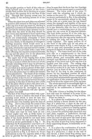
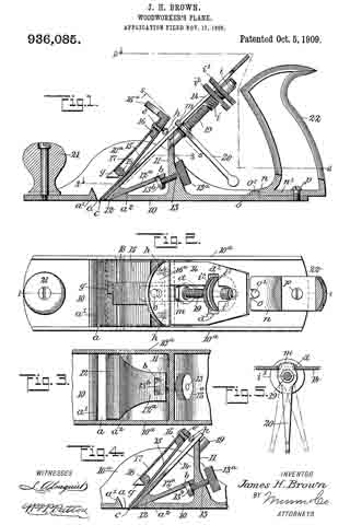
Figure 1 is a partly sectional side view of the improved plane, substantially on the line 1–1 in Fig. 2; Fig. 2 is a partly sectional plan view, substantially on the line 2–2 in Fig. 1; Fig. 3 is a fragmentary plan view, partly in section on the line 3–3 in Fig. 1; Fig. 11 is a sectional side view of details shown in Fig. 1, but showing a changed adjustment thereof and Fig. 5 is a partly sectional view of parts, taken substantially on the line 5–5 in Fig. 1.

The stock for the plane is cast into form from metal, and essentially consists of a flat base plate 10 having vertical walls 10a formed along its side edges, and said side walls having their greater height near their longitudinal centers are curved on their upper edges, as shown for one side wall in Figs. 1 and 4. At a suitable distance from the front end of the stock 10, a transverse throat opening a is formed in the base portion thereof, and at the front and rear edges of said throat, oppositely inclined defining walls a1, a2 are formed on said base portion, as is clearly shown in Fig. 1. Rearward of the throat opening a and parallel therewith, a post 11 is erected on the base 10, said post extending from one side wall 10a to the opposite one, as shown in Figs. 1 and 3, and being located near the longitudinal center of the plane stock.

Novel means is employed for graduating the width of the slot opening a, consisting in the provision of a wedge-shaped tongue piece 12, seated upon the inclined rear defining wall a2 of the slot a, said tongue piece extending across the stock into loose engagement with the inner surfaces of the side walls 10a. The tongue piece 12 is provided with a rearward extension 12a in the form of a flat plate, having at its end a fork 12 projecting from its lower face and adjacent to said fork a cross slot b. The post 11 is thickened near its junction with the base 10, and in said thickened portion a threaded perforation is formed, in which the threaded body of an adjusting said screw screw 13 is screwed, said screw having a roughened head 13a formed or secured on the rear end thereof. The screw 13 extends between the members of the fork 12b and is provided at its end with a collar 13b which projects into the slot b, so that by manipulating the screw the tongue piece 12 can be adjusted to increase or decrease the width of the slot a. The connection between the tongue and screw, permits the tongue to be readily detached from the screw and removed when desired.

The cutter bit 14 of the plane, is in the form of a flat metal plate, preferably formed of steel and having one end beveled to produce a transverse cutting edge c thereon. At the transverse center, a longitudinal slot d is formed in the cutter bit 14 extending of a suitable length between the ends thereof. The cutter bit 14 is seated upon the tongue piece 12 and the upper end of the post 11, said end being sloped forward and downward, as shown in Fig. 1, to adapt it for a proper support of the bit. The bit 14 is held seated upon the tongue piece 12 and post 11 by a novel clamping device that also serves the purpose of a cap plate for the cutter bit, said device comprising the following details: A resilient thin metal plate 15 having a proper length, and a width that is equal with that of the cutter bit, is secured by one end that is uppermost in service upon a spacing block 16 whereon a resilient hook plate 17 is also secured. The spacing block 16 is a flat rectangularly-edged slab of metal from the rear end of which projects a flange 16a at a right angle, said block having parallel sides. The hook is of an equal width with the resilient cap plate 15, and these plates at their upper ends are oppositely lapped upon the upper and lower surfaces of the spacing block 16, whereon they are secured by a rivet or screw, as shown at e. Upon the lower or forward end of the plate 17, a transverse hook g is formed, that is adapted for a hooked engagement with a keeper bar 18 that extends across the stock of the plane above and in contact with the cap plate 15, and is secured by its ends in the side walls 10a of said stock. It will be seen that the hooked engagement of the plate 17 with the keeper bar 18, will hold the cap plate 15 imposed upon the cutter bit 14; and to enforce said engagement set screws h are inserted in the cap plate and spacing block 16, that will graduate the pressure of the cap plate in accord with the degree of projection given the set screws, that bear on said cutter bit near each side edge thereof, as shown in Figs 1, 2 and 4.

In the post 11, near its upper edge, a screw 19 is secured by one end thereof, and thence extends rearward and upward. Upon the threaded body of the screw 19, a sleeve nut i1 is loosely mounted, said nut having a radial flange i formed thereon, and upon a portion of the cylindrical body of said nut, a thread is cut. Upon the threaded body of the nut i1, a nut i2 having a body similar to the flange i is adjustably mounted and adapted for rotatable movement toward or from the flange i. Near the upper end of the cutter bit 14, a transverse slot d1 is formed that crosses the longitudinal slot d. Below the slot d, the adjusting screw 19 is positioned and in such close relation to the cutter bit 14 that the radial flange i1 and the nut i2 will project into the transverse slot a1 and by lateral adjustment may be caused to have lateral contact with the side edges of said slot.

It will be seen that by a screwed adjustment of the nuts i, i2, on the body of the adjusting screw 19, there may be an exact longitudinal adjustment given to the cutter bit let for its projection or retraction in the transverse throat slot a; further, by screwing the flange i1 and nut i2 into an engagement with the defining sides of the cross slot d1, the cutter bit 14 will be firmly held at a desired point of longitudinal adjustment thereof.

Upon the adjusting screw 19, near the post 11, a lever 20 is mounted and secured near one end thereof, a toe m extending from the upper end of said lever through the slot d, having a loose engagement with the defining side edges thereof, the main portion of said lever projecting down near to the base 10, and it will be noted that a side movement of the lever will slightly rock the cutter bit 14 accordingly and thus depress a respective corner of the cutting edge of the bit, enabling an exact adjustment of said edge to adapt it to have a true bearing on the material over which the plane is moved in planing it.

At the front end, a knob 21 is secured that projects vertically from the plane stock, this being a common provision to enable hand pressure to be applied upon the front end of the plane.

The handle 22 of the plane, is provided with a forwardly-projecting flange n at the lower end thereof, said flange having a notch o in the front edge, which receives a stud o1 formed on the rear portion of the base of the stock at its transverse center. The body of the handle 22, is preferably given skeleton form, that affords a flat bottom wall n1 thereon, which is centrally perforated and registers with a threaded perforation formed at the transverse center of the base portion 10; and it will be seen that if the stud o1 is placed in the notch o and a screw p is inserted through the perforation in the handle down into the threaded perforation in the base 10, the handle 22 will be firmly but detachably secured upon the plane stock.

It will be apparent from the foregoing description, that the cutter bit 14 may be given different degrees of inclination on the stock by an adjustment of the tongue piece 12 toward or from the throat slot a; the cap plate 15 may be adjusted for graduating its pressure on the cutter bit and is not connected therewith other than by frictional contact. The provision of the adjusting screw 19 and flanged nuts i and i2 thereon that are adjustable in the cross slot d1, greatly facilitates the exact adjustment of the bit 14 so as to cut a thick or thin shaving from the material operated upon, and this in conjunction with the lever 20 enables a close accurate adjustment to be given to the edge of the cutter bit.

Having thus described my invention, I claim as new and desire to secure by Letters Patent:

1. In a plane, the combination with a stock having a base portion and side walls thereon, said base having a transverse throat opening therein, a post erected on the base a distance rearward from the throat opening, and a cutter bit seated upon the tongue piece and upon the post, of a clamping device comprising a resilient cap plate, a hook plate, a spacing block whereon the end portions of the cap plate and hook plate are secured, a hook formed transversely on the free end of the hook plate, a keeper bar secured at its ends in the side walls of the stock and whereon the hook plate is hooked, and means for enforcing spring pressure of the clamping device upon the cutter bit.

2. In a plane of the character described, the clamping device for the cutter bit, comprising the resilient cap plate, the hook plate having a hook on one end thereof, the spacing block secured between the adjacent ends of the cap plate and hook plate, and adjusting screws carried by the spacing block.

3. In a plane, the combination with a stock having a transverse member, and a cutter bit, of a resilient cap plate engaging the bit, a member carried by the cap plate and engaging the transverse member of the stock, and means for increasing the pressure of the cap plate upon the bit.

4. In a plane, the combination with a stock having a transverse member above the base thereof, and a cutter bit, of a resilient cap plate engaging the bit, a member secured at its upper end to the cap plate and having a hook at its lower end engaging the transverse ineniber of the stock, and screws arranged between the cap plate and bit for increasing the pressure of said cap plate.

5. In a plane, the combination with a stock having side walls and provided with a bar extending between the side walls of the stock, and a cutter bit, of an angular block, two resilient plates secured upon opposite sides of one member of the said block, one plate resting upon the cutter bit and the other provided with a hook at its free end engaging the said bar, and screws projecting from the inner face of the said block and engaging the cutter bit.

In testimony whereof I have signed my name to this specification in the presence of two subscribing witnesses.

JAMES HORACE BROWN.

Witnesses:
MICHAEL F. HART,
F. HOWARD HALLETT.

No. 946,178 – Combination Woodworking-Plane (Mardonious L. Carter) (1909)

[paiddownloads id=”667″]946178


UNITED STATES PATENT OFFICE.

_________________

MARDONIOUS L. CARTER, OF GLASSPORT, PENNSYLVANIA.

COMBINATION WOODWORKING-PLANE.

_________________

946,178. Specification of Letters Patent. Patented Dec. 14, 1909.
Application filed February 13, 1909. Serial No. 477,535.

_________________

To all whom it may concern:

Be it known that I, MARDONIOUS L. CARTER, a citizen of the United States, residing at Glassport, in the county of Allegheny and State of Pennsylvania, have invented certain new and useful Improvements in Combination Woodworking-Planes; and I do declare the following to be a full, clear, and exact description of the invention, such as will enable others skilled in the art to which it appertains to make and use the same, reference being had to the accompanying drawings, and to the letters and figures of reference marked thereon, which form a part of this specification.

This invention relates to an improved combination wood-working plane for carpenters’ use, and it comprises a plane proper carrying the bits which in itself forms what is known in the art as a “smoothing plane” a detachable rear extension and means for securing the same which when in position converts said smoothing plane into a “jack plane” or one of greater length and by a further addition of a forward extension in addition to that of the rear the plane answers the purpose of a “fore plane”, and the invention further consists in the certain details of construction of parts as will be fully described hereinafter.

In the accompanying drawings:– Figure 1, is a central side sectional elevation of my improved combination plane showing the same converted into a fore-plane, the same being constructed and arranged in accordance with my invention. Fig. 2 is a similar view partly in elevation, showing the implement converted into at smoothing plane, the rear and forward extensions being adjusted and secured above the level of the base of same. Fig. 3 is a plan view of the converted fore plane, as shown at Fig. 1. Fig. 4; is an end elevation of the same. Fig. 5 is a cross section, taken on the line x x of Fig. 1.

To put my invention into practice and thereby construct a convertible hand plane for carpenters’ and joiners’ use and provide a combination of these planes in one, I form from cast metal a middle section which comprises a flat base 1, upwardly projecting sides 3, extending the entire length of said base, a cross portion 4 located above the throat 5 and an inclined integral rest 6 upon which the bits 7 are held by means of a plate 3 and screw 9 and rigidly secured by a thumb screw 10 operating in connection with a pivoted dog 11.

The above described construction differs but slightly from an ordinary smoothing plane such as are now in common use.

The base 1 of the middle section is rabbeted or reduced to one-half its thickness both at its forward and rear ends 2, and two threaded openings 17′–29′ formed through the base, and suitably located openings in the two side flanges 3 for the reception thumb screws 20 and 32 for the purpose securing the front and rear extensions, as will be fully described hereinafter.

The rear extension of the plane consists of a flat base 27 having side flanges 31, a rabbeted or reduced forward end 28 to register with and engage with the reduced rear end of the plane proper. Formed with this base 27 are parallel arranged dovetailed slides 36, which extend in the direction of its length and are adapted to contain a sliding dovetailed strip 35, in such manner that said strip may move freely therein. This strip 35 is secured rigidly in a certain position by means of thumb screws 29–30, engaging with the threaded opening 29′ in the base 1 of the plane proper and with a similar opening 30′ formed in the base of the extension, as will be best seen by reference to Fig. 1 of the drawings. This rearward extension is further secured and made more rigid with the plane proper by means of thumb screws 32 passing through the side flanges 3 and engaging with threaded openings formed in the flanges 31 of said extension (see Figs. 3 and 5) this making a permanent and rigid connection between the parts. The movable dovetailed member 35 carries an ordinary handle 33, such as are used on all wood planes said handle being attached by a screw 34 at the forward end and by another passing down through the same.

At the rear end of the base 27 of the rear extension is a threaded opening 30, and like openings 35′ are formed in the side flanges of the same, by means of which together with the thumb screws 32, this said extension may be adjusted to the position shown at Fig. 2 of the drawings, having first released the screws 29–30, moved the sliding member 35 back until the thumb screw 29 may engage with the forward threaded opening of the base 27 at which time the side screws 32 are adjusted to make a rigid connection of the parts. This backward movement of the sliding member 35 will bring the handle 33 and adjust the other parts to form the smoothing plane, the whole having been moved forward and on the top of the base 1 of the plane proper, and when in this position the forward extremity of the guides 36 will project beneath an offset 26 formed beneath the inclined bit rest 6′ and prevent any lateral or vertical movement of the extension.

The forward end of the plane proper is also fitted with an adjustable extension, the same consisting of a base 12, rabbeted to register with the front rabbet of the base 1, side flanges 14, parallel dovetailed guides 24 in which a corresponding movable member 23 operates in the direction of its length. This forward extension is secured in line with the plane proper by means of two thumb screws 17 and 18, together with side screws 20 in the same manner as that of the previously described rear extension. The sliding member 23 carries a knob or hand hold 16, common to planes of this class and when the said extension is in position to form a fore plane (as at Fig. 1) said sliding member is projected into a slot 25 formed at the base of the partition 41, and the extension held rigid with the plane proper by thumb screws 17 and 18, engaging the base of said extension and with the base of the plane proper. In addition to these two securing screws 17–18, side screws 20 are used which pass through the fianges of the two members, as will be seen by reference to Figs. 1 and 4.

To adjust the forward extension when the implement is to be used as a smoothing or jack plane the two screws 17–18 are released, the sliding member 23 moved back and the one screw 18 engaged with the threaded opening 19 and the extension more to a position on the top of the base 1 of the plane proper, the rear end of the sliding member 23 entering a pocket 22 formed in the partition at and the rear end of the base resting upon strips 25′ (see Fig. 2). The extension is now secured in this position by the side clamping screws 20.

By placing the front and rear extensions in position as at Fig. 1, a fore plane is formed, the handle 33 being first adjusted to the proper position.

To form a jack plane it is only necessary to adjust the forward extension to the position shown at Fig. 2, leaving the rear extension adjusted as shown at Fig. 1, and in order to convert the implement into a smoothing plane the front and rear extensions occupy a position as shown at Fig. 2.

The advantages of a convertible plane construction, as described are many, as is obvious among which are cheapness, as it takes the place of the three ordinary smoothing planes required for all ordinary carpenters’
practice, and it may be adjusted to occupy the minimum of space in a carpenter’s tool chest.

Various slight modifications and changes may be made in the details of construction without departing from the spirit of the invention. Therefore, I do not wish to confine myself to the construction, shown and described, but wish to claim all such modified forms as would come properly within the general scope of the invention.

Having thus described my invention, what I claim and desire to secure by Letters Patent, is:–

1. A bench plane, comprising a. plane proper, an extension therefor, means for attaching the extension with its sole in line with the plane sole, or with the sole in contact with the inner sides of the main sole plate, and a handle adjustable along the extension.

2. A bench plane, comprising a plane proper, a rearward extension therefor, means for attaching the extension with its sole in line with the plane sole, or with its sole in contact with the inner side of the main sole plate, and a handle adjustable along the extension, in combination with a forward extension, an adjustable knob carried by said extension, and means for locking said adjustable knob and extension to the plane proper.

In testiniony whereof, I affix my signature, in presence of two witnesses.

MARDONIOUS L. CARTER.

Witnesses:
W. G. WALTER,
ARTHUR V. McKEE.

No. 940,324 – Oil-Cup For Planes (David James) (1909)

[paiddownloads id=”666″]940324


UNITED STATES PATENT OFFICE.

_________________

DAVID JAMES, OF COFFEYVILLE, KANSAS.

OIL-CUP FOR PLANES.

_________________

940,324. Specification of Letters Patent. Patented Nov. 16, 1909.
Application filed June 22, 1907. Serial No. 580,239.

_________________

To all whom it may concern:

Be it known that I, DAVID JAMES, citizen of the United States, residing at Coffeyville, in the county of Montgomery and State of Kansas, have invented new and useful Improvements in Oil-Cups for Planes, of which the following is a specification.

My invention relates to improvements in oilers for planes.

The object of my invention is to provide a device of the character described, in which the lower face of the plane can be supplied with the proper amount of oil, and by which the oil supply opening can not be filled with dirt and prevent the proper operation of the oiler. Neither will the oil run from the oil cup when the plane is inverted.

Another object of my invention is to provide a more simple, cheap and effective oiler of this character to accomplish the result desired.

ln the accompanying drawings: Figure 1 is a longitudinal vertical sectional view of a plane, showing my improved oiler applied thereto; Fig. 2 is a top plan view of the plane partly broken away; and Fig. 3 is an enlarged detached view of the valve showing the several parts removed or separated from each other.

Referring now to the drawings, 1 represents a plane which is of the ordinary structure and having the usual boss 2 adjacent its forward end to which is attached an ordinary knob 3 for operating the same. In my improved oiler, this knob forms the oil cup, and, as shown, is of a spherical shape and hollow so as to receive and hold the oil. As shown, the boss 2 is externally screw-threaded and the oil cup provided with an internally screw-threaded opening 4, which is screwed upon the boss. The said boss is provided with a central opening 5 which extends through the lower face of the plane 6 and through which the oil passes to the lower face of the plane. The oil cap has an inwardly extending flange 7 which extends over the upper end of the boss and is provided with an opening 8 corresponding with the opening 5 in the boss. The said opening, at its upper end, is provided with an annular flange 9, the lower face of which forms the seat for the valve, as will be hereinafter more fully described.

The upper end of the oil cup is provided with an enlarged opening 10 through which the oil is placed in the cup and in which the operating button is placed. Within the oil cup is a vertically disposed valve stem 11 which extends downwardly through the opening within the flange 9 and below the same has rigidly secured thereto a valve 12, which, as shown, is of a circular form and fits firmly against the lower face of the flange 9 and forms a tight joint to prevent the escape of oil from the cup. The stem 11, adjacent its upper end, is screw-threaded and screwed thereon is a nut 13. Coiled upon the stem, below the nut, is a coil-spring 14 which has its lower end bearing upon the flange 9 and normally forces the valve stem upwardly and holds the valve firmly to its seat.

Screwed upon the extreme upper screw-threaded end of the valve stem is a head 15 which is of a size approximating that of the opening 10 and is provided with a reduced externally threaded sleeve 16 extending within the oil cup. Carried by this sleeve is a washer 17, preferably of leather, which engages the walls of the opening 10 and prevents the oil from leaking therefrom. Below the washer and carried by the sleeve is a nut 18 which is adapted to expand the washer and insure a perfect fit with the walls of the openings.

In order to prevent the screw-head from turning and accidental displacement from the valve stem, I provide the upper face of the oil cup, adjacent the opening 10, with an annular recess 19, having a screw-threaded opening into which is screwed a flat-headed screw 20, and the screw-head 15 is provided with a recess 21 into which the flat-headed screw 20 extends and prevents the head from turning. The head of the screw has a curved cut-away portion 22 which, when turned in its proper position, allows the head to be turned.

The valve stem 11 has its lower end screw-threaded at 23 and screwed thereon is a sleeve nut 24, the head portion of which fills the opening 5 in the boss and prevents the dirt, etc., from filling this opening 5. By turning this nut, it will be seen that the same can be adjusted so that it will hit a slight distance above the lower face 6 of the plane.

By pushing upon the screw-head, it will be seen that the valve stem is forced downwardly against the tension of the spring and the valve is unseated. The sleeve nut is likewise carried downwardly clearing the opening 5 of all the dirt and allows the oil to freely flow downwardly to the lower face of the plane. When the screw-head is released, it resumes its normal position and should the plane be inverted no oil will leak therefrom.

Having thus fully described my invention, what I claim as new and desire to secure by Letters Patent, is:

1. The combination with a plane, of an oil cup attached to the upper face of the plane and in communication with the lower face of the plane, a valve controlling the flow of oil from the cup, and a plug carried by the valve for preventing the communication from being filled with dirt.

2. The combination with a plane, of an oil cup attached to the upper face of the plane and in communication with the lower face of the plane, the cup having a filling opening therein, a valve controlling the upper end of the lower communication, a plug carried by the valve for closing the lower end of said opening, a valve stem carried by the valve and extending within the filling opening, and a head within the filling opening for closing the same and adapted to operate the valve stem.

3. The combination with a plane, of an oil cup attached to the upper face of the plane and in communication with an opening through the plane, the oil cup having a filling opening, a head closing said opening and having a screw-threaded sleeve extending within the oil-cup, an elastic washer carried by the sleeve and engaging the walls of the filling opening, a nut on said sleeve for expanding the washers, a valve stem screwed within the sleeve, a valve carried by the stem and controlling the opening through the plane, and means carried by the stem for preventing the last named opening from being filled with dirt.

4. The combination with a plane, of an oil cup attached to the upper face of the plane and in communication with an opening through the plane, the oil-cup having a filling opening, a head closing said opening and having a recess in its upper face, a screw carried by the oil-cup and having its head extending within the recess, the said head having a cut-away portion to correspond with the curvature of the screw-head, a sleeve carried by the head and extending within the oil cup, an elastic washer carried by the sleeve and engaging the walls of the filling opening, a nut on said sleeve for expanding the washer, a valve stem screwed within the sleeve, a flange surrounding the opening through the plane and forming a valve seat on its lower face, a valve carried by the stem, a spring surrounding the stem between the sleeve and the flange and normally holding the valve stem upward with the valve seated, and a screw sleeve screwed upon the lower end of the valve stem and normally filling the lower end of the opening extending through the plane for preventing the same from being filled with dirt.

5. The combination with a plane, of an oil cup attached to the upper face of the plane and in communication with the lower face thereof, a vertically disposed valve stem within the oil cup and having a valve carried thereby and working in combination with a valve seat within the cup, and a plug carried by the lower end of the valve stem and closing the communication between the oil cup and the lower face of the plane.

6. The combination with a plane, of an oil cup attached to the upper face of the plane and in communication with the lower face thereof, a vertically disposed valve stem within the oil cup and having a valve carried thereby and working in combination with a valve seat within the cup, a valve stem carried by the valve and extending into the filling opening, a head closing the filling opening and adapted to operate the valve stem, a plug carried by the lower end of the valve stem within the communication between t.he oil cup and the lower face of the plane, and means connected to the valve stem for normally holding it in an upward position with the plug flush with the lower face of the plane.

In testimony whereof I have affixed my signature, in presence of two subscribing witnesses.

DAVID JAMES.

Wittnesses:
J. B. ELLIS,
N. M. JANSSEN.

No. 930,307 – Plane (Charles E. Mitchell And Edmund A. Schade) (1909)

[paiddownloads id=”664″]930307


UNITED STATES PATENT OFFICE.

_________________

CHARLES E. MITCHELL, OF NEW YORK, N. Y., AND EDMUND A. SCHADE, OF NEW BRITAIN, CONNECTICUT, ASSIGNORS TO THE STANLEY RULE & LEVEL COMPANY, OF NEW BRITAIN, CONNECTICUT, A CORPORATION OF CONNECTICUT.

PLANE.

_________________

930,307. Specification of Letters Patent. Patented Aug. 3, 1909.
Application filed May 6, 1902. Serial No. 106,200.

_________________

To all whom it may concern:

Be it known that we, CHARLES E. MICHELL and EDMUND A. SCHADE, citizens of the United States, residing at New York, N. Y., and New Britain, Connecticut, respectively, have invented certain new and useful Improvements in Planes, of which the following is a full, clear, and exact description.

Our invention relates to improvements in the construction of planes, and particularly to the parts which are adapted to carry and provide adjustment for plane irons in that class known as bench planes.

The part of the plane which immediately supports the cutting tool or plane iron is commonly termed a frog. This part is so constructed as to bear upon and be supported by the stock portion of the plane and to itself carry and provide means for adjusting the position of the iron. This frog is commonly constructed of cast iron and separate from the base or stock portion of the plane. Frogs constructed in this manner of cast metal are heavy, and having the usual characteristics of such metal, are easily broken and but poorly adapted to withstand the strains to which such a structure is subjected. The great weight is also a material element in considering the usefulness and general utility of a plane. For this reason, it is desirable that the parts shall he made as light as possible and consistent with a requisite strength. In casting such a body as this, it is not feasible to make it of such a finish as to be immediately useful in the final construction which is desired. For this reason it is necessary that it should be put through several finishing operations under machine tools in which the surfaces are given the proper angles relatively to one another and finished to present satisfactory bearing surfaces and appearance. Being of irregular and peculiar shape, there are moreover set up in a frog strains due to the unequal cooling of the metal in different parts of the frog consequent upon the casting operation. These strains are likely to and often do cause checks and irregularities in the structure to such a degree that the parts are the more easily subject to fracture when used in the ordinary course of business. Even if actual defects do not appear on the surface of the metal, there sometimes are such initial strains in the interior as to seriously impair the strength of the parts. For these reasons and in order to make the structure in a more simple and economical manner we have constructed the parts of sheet metal which may he for instance cold rolled steel. ln this way a very light, reliable and economical structure is effected which in its use is most satisfactory and durable.

ln the drawings: Figure 1 is a side elevation partly in section of a plane embodying the improvements of our invention. 2 is a perspective view from the rear of the parts which immediately support a plane iron. Fig. 3 is a rear elevation of the same with what may be termed yoke portion of Fig. 4. Fig. 4 is a perspective view from the front of this so-called yoke portion. Fig. 5 is a view partly in section of the Y-adjustment lever which is used with the part of Fig. 2. Fig. 6 is a side elevation and section of the plane iron supporting member and adjusting devices.

In Fig. I the stock or base portion of the plane is represented as shown at 1 which may have as usual a rear handle and a forward knob for convenience in handling the same. In the base of the stock portion is provided the usual throat or opening 10, and to the rear a chair or seat 13. Above the chair is supported the part 2 which may he herein termed the frog and which provides the immiediate support or bearing for a plane iron. Beneath this frog is what may be conveniently termed a yoke portion 3 which may he attached to the frog as hereinafter set forth. The plane iron 4 which rests upon the face of the frog is in the form shown provided with a plate 5 at its upper surface. These are in turn held in place by a cap iron 6 and are provided with the Y-adjustment lever 7 coacting with an adjusting nut 8. A laterally adjusting lever 9 is secured at the top of the frog.

The yoke portion 3 which is formed at the lease in a manner suitable to cooperate with the chair portion 13 of the stock 1, is provided with slots or holes 30. Through these holes pass the screws 31 which secure the yoke portion to the base and thus provide a forward and backward adjustment for the position of the frog. The front end 32 of the base portion of the yoke may be bent downward at an angle to correspond with the under surface of the face of the frog to which it may be secured, as for example by rivets. The upright portion or back of the yoke extends upward and is secured at the downwardly bent portion 36 to the frog at a point just above the opening 20 in the face of the frog. Through this opening access may be had readily to the securing screws 31 in the base.

When the plane iron and plate are adjusted in position and secured to the frog by means of the cap iron 6 and cap screw 61, the frog is subjected to stresses of considerable amounts. To provide for meeting these stresses it is desirable that the sides of the frog should be bent down and depressed to form reinforcing flanges. It will be noted that these flanges as shown are substantially triangular in form and correspond in depth from the face of the frog very closely to the diagram of changes in bending moments which would occur in a beam loaded in the center and supported at the ends, which is the case that we have herein. The cap iron 6 is provided with a cam lever 65 for effecting the requisite pressure between the cap and the plane iron or the plane iron plate for holding the parts in place.

The upper end of the bearing face of the frog is depressed in a truss-like form at 29 to provide a recess in which the lower end of the aterally adjusting lever 9 may be pivoted at 92 and operate. The end of this lever 9 may be provided as is usual in planes of this character with a disk 94 which cooperates with a slot 40 in the plane iron 4 to effect the desired lateral adjustment. The depth of the cutting edge of the instrument may be adjusted by means of what is known as a Y-adjustment 7 in which the nose 75 projects forward through an opening in the face of the frog into a hole 50 in the plate which is above the plane iron. The plane-iron and plate being secured together by the screw 45, movement up and down of the Y-adjustment will also operate the plane iron itself.

The face of the frog is provided with a perforation or recess to receive the head of the securing screw which is thus let into the platform and allows the plane iron to have a smooth and even bearing upon the face of the frog. Above this recess the metal of the frog may be cut out and bent back in the form of ears 27 which will provide bearings for the pivot of the Y-adjustment. In order that these ears may be bent back at convenient angles and with as little injury to the metal as possible, it is desirable that the sides of the recess should be cut back both above and below the ears and at the base thereof as shown particularly in Fig. 3. ln order that the Y adjustment 7 may have a secure and even bearing and also to increase the economy and efficiency of the device, we have made the Y-adjusting lever 7 of sheet metal as shown in Fig. 5, in which 70, 70 are perforations in the two opposite sides of the lever to provide for the pivot pin. It will thus be seen that the lever has two bearings and that they are spaced apart a considerable distance. The lower ends of the arms 78 coact with the adjusting nut 8 which operates on the screw 81. in this construction as shown particularly in Fig. 6 the adjusting screw 81 is conveniently seated in the back of the yoke at a point near the top thereof where the strength and rigidity of the same would be sufficient to give it a secure bearing. lt is also desirable that the face of the frog should have a reinforcing piece at the point where the cap screw 61 is attached thereto. The bent down portion 36 of the yoke provides this in a most satisfactory manner. By this structure also the cap screw tends to aid in holding the yoke and the frog more securely together. The upper portion 33 of the back of the yoke may be out away as appears most clearly in Fig. 3, and thus provide an easy and convenient access for the purpose if desired of riveting the plate 36 to the frog 2. The lower front end of the yoke acts also as a reinforcement to the lower front edge or toe of the frog in the structure herein shown, and materially adds to the strength and efficiency of the parts since the pressure of the lower end of the cap iron 6 is applied near this point. The cutting edge of the plane iron may be projected through the throat or slot 10 in the base of the stock portion just in front of the toe of the frog. The face of the frog is also reinforced as shown by the depressed portion 29 which in stamping the article forms a corrugation at that point substantially opposite the point of application of the pressure applied by the cam lever 65 at the upper end of the cap iron.

The whole structure is exceedingly light in weight and although very simple and economical in its construction is durable and efficient.

The yoke 3 forms a backing for the plane-iron and may be referred to in some of the claims by the term backing or frog backing.

What we claim is:

1. In a plane the combination of a stock-portion having a throat therein for the passage of a plane-iron, a chair at the rear of said throat, a sheet metal frog adapted to sit upon said chair, a plane-iron bearing against the face of said frog, a plate for said plane-iron, a screw for securing said plane-iron and said plate together, a perforation through the face of said frog forming a cavity to receive the head of said screw the head of said screw being accessible from the rear of said frog, the sides of said frog being depressed to form supporting flanges, substantially as described.

2. In a plane the combination of a stock-portion having a throat therein for the passage of a plane-iron, a chair at the rear of said throat, a sheet metal frog sitting upon said chair, a plane-iron bearing against the face of said frog, a plate reinforcing said plane-iron, a screw for securing said plane-iron and said plate together, a recess in the face of said frog forming a cavity to receive the head of said screw, pivot ears formed from the metal of the face of said frog and bent above said recess forming bearings for the pivot of an adjustment lever.

3. In a plane the combination of a stock-portion having a throat therein for the passage of a plane-iron, a chair at the rear of said throat, a sheet metal frog sitting upon said chair, a plane-iron bearing against the face of said frog, a plate for said plane-iron, a screw for securing said plane-iron and said plate together, a perforation through the face of said frog forniing a cavity to receive the head of said screw, pivot ears formed frori the metal of said frog and above said cavity forming bearings for the pivot of an adjustment lever, said adjustinent lever being formed of sheet metal and having bearings in the opposite sides thereof, substantially as described.

4. In a plane the combination of a stock-portion having a throat therein for the passage of a plane-iron, a raised chair at the rear of said throat, a sheet metal frog for said chair, a plane-iron bearing against the face of said frog, a plate over said plane-iron, a screw for securing said plane-iron and said plate together, a perforation through the face of said frog forming a cavity to receive the head of said screw the head of said screw being accessible from the rear of said frog, the sides of said frog being depressed and forrning triangular shaped supporting flanges for said frog resting on said chair, the forward edge of said frog projecting downward beyond the chair and resting on the sole back of the throat and forward of the chair.

5. In a plane, a stock-portion having a chair seat therein, a frog adapted to support a plane-iron and adjacent parts, the sides of said frog being depressed to form supporting and reinforcing flanges and a sheet metal yoke portion secured to said frog, and means for securing said yoke portion to said frog portion, substantially as described.

6. In a plane, the combination of a stock-portion, a frog for supporting a plane-iron, the said frog being formed of sheet metal having the opposite sides depressed to forrn supporting and reinforcing flanges, a yoke secured to said frog forming a seat for said frog, and a screw secured in said yoke portion and adapted to carry a means for adjusting the cutting depth of a plane-iron.

7. In a plane, a stock-portion having a chair therein, a sheet metal frog adapted to support a plane-iron, screws for securing said frog to said stock-portion, a perforation through the face of said frog to permit of access to the said screws, a plane-iron having a plate at the top thereof, a screw for securing said plate and said iron together, a perforation in the face of said frog to receive the head of said screw, a lever for laterally adjusting the position of said plane-iron, a depressed portion from the face of said frog to form a recess to receive said laterally adjusting lever, pivot ears struck from the metal of said frog and bent down to form bearings for an adjustment lever, the metal of the face of said frog being cut away above and below at the sides of said ears, substantially as described.

8. ln a plane, a stock-portion having a chair therein, a sheet metal frog adapted to support a plane-iron, screws for securing said frog to said stock-portion, a perforation through the face of said frog to permit of access to said screws, a plane-iron having a plate at the top thereof, a screw for securing said plate and said iron together, a perforation in the face of said frog to receive the head of said screw, a lever for laterally adjusting the position of said plane-iron, a depressed portion from the face of said frog to form a recess to receive said laterally adjusting lever, pivot ears struck from the metal of said frog and bent down to forrn bearings for an adiustrnent lever, the metal of the face of said frog being out away at the sides of said ears, and a yoke portion secured to said frog forming a reinforce therefor, and providing a bearing for a cap screw and also a bearing for an adjusting screw.

9. ln a plane, a sheet metal frog forrned with depressed side flanges, a sheet metal yoke having slots in the base thereof for adjusting-screws, said yoke being bent down at the upper portion and secured to the underside of the face of said frog, substantially as described.

10. ln a plane, a sheet metal frog formed with depressed side flanges, a sheet metal yoke having slots in the base thereof for adjusting-screws, said yoke being bent down at the upper-portion and secured to said frog, and a cut out portion in the face of said frog below the point of attachrnent of the upper end of said yoke, whereby access may be had to the slots in the base of said yoke, as and for the purpose specified.

11. In a plane, a frog formed of sheet metal having the sides depressed to form supporting flanges , a yoke formed of sheet metal and separately therefrom but united to the underside of the face thereof at the lower end and also at the upper end by a bent down portion, substantially as described.

12. ln a plane, a stock-portion, a frog for and forming a bearing for a plane-iron, means for securing said frog to said stock-portion, a plane-iron secured to the face of said frog, a plate secured to said plane-iron, a screw for fastening said plate to said iron, a recess in the face of said frog forming a cavity to receive the head of said screw, bearings formed integral with said frog and above said recess, an adjustment lever formed of sheet metal and having its nose projecting upward into a hole in said plate and having bearings in the two opposite sides thereof for a pivot therefor, and means for operating said adjusting lever, substantially as described.

13. In a plane, a stock-portion, a frog for and forming a bearing for a plane-iron, means for securing said frog to said stock-portion, a plane-iron secured to the face of said frog, a plate secured to said plane-iron, a screw for fastening said plate to said iron, a recess in the face of said frog forming a cavity to receive the head of said screw, pivot bearing ears formed integral with said frog, the face of said frog being out away at the sides near the upper and lower edges of each pivot bearing ears for the purpose specified.

14. In a plane, a stock-portion, a frog for supporting a plane-iron, a yoke portion formed of sheet metal and secured to said frog portion and having slots in the base thereof for receiving securing screws and a support in the rear thereof for carrying a Y-adjustment screw.

15. In a plane, a frog formed of sheet metal having a perforation near the top thereof to receive a screw-head, a yoke portion formed of sheet metal and at its lower forward edge parallel to the face of said frog portion, the base of said yoke portion being bent back from the face of said frog to form a bearing surface and slotted to receive securing screws, the back of said yoke portion being adapted to form a bearing for an adjustment lever screw, and means for securing the upper end of said yoke to said frog.

16. In a plane, a frog formed of sheet metal having a recess near the top thereof to receive a screw-head, a yoke portion formed of sheet metal and secured at its lower forward edge to said frog portion, the base of said yoke portion being bent back from said frog and having holes to receive securing screws, the back of said yoke portion being adapted to form a bearing for an adjustment screw, the upper end of said yoke being bent downward and forward and parallel to the face of said frog, and means for securing said bent down portion to said frog.

17. In a plane, a frog formed of sheet metal adapted to support a plane iron, a yoke portion formed of sheet metal and at its lower forward edge secured to said frog portion, the base of said yoke portion having holes to receive securing screws, the back of said yoke portion being adapted to form a bearing for an adjustment screw, the upper end of said yoke forming a supporting means for a cap screw.

18. In a plane, a frog formed of sheet metal adapted to form a bearing for a plane iron, a yoke-portion formed of sheet metal and secured at its lower edge to said frog portion, the base of said yoke portion having holes to receive securing screws, the back of said yoke portion being adapted to form a bearing for an adjustment screw, and means for securing the upper end of said yoke to said frog, the sides of said frog being depressed to form reinforcing flanges about said yoke portion.

19. In a plane, a plane stock, a chair portion therein, a frog adapted to carry a plane-iron, a sheet metal yoke secured to said frog having a base portion and being secured at its upper portion to the said frog and having a back portion extending from said upper portion to said base, said back portion being narrowed at the top adjacent said top portion to facilitate attaching the said top portion to the said frog.

20. A frog for a plane said frog being formed of wrought metal, the opposite edges being turned downwardly, a sheet metal frog-backing to the rear and underneath said frog, permanently secured to the frog, and means for removably securing the backing to the plane stock.

21. In a plane, the combination of a stock portion, a frog formed of sheet metal and adapted to support a plane iron said frog having downwardly extending flanges formed integrally with its face, a rearwardly extending sheet metal member carried by said frog and substantially parallel to the upper surface of the sole of said stock portion an upward extension therefrom secured to the back of the frog and means for securing said frog to said stock portion whereby it may be adjusted backward and forward on its seat.

22. In a plane, a plane stock, a frog formed of sheet metal and having reinforcing side flanges, a sheet metal frog-backing formed separately from said stock and said frog, means for securing said backing to said frog and means for adjustably securing said backing to said stock to permit said frog to be adjusted to and fro and a passage through the frog to afford access to the last mentioned means.

23. A frog for a plane, said frog being formed of sheet metal, downwardly extending integral side flanges and a separately formed sheet metal downwardly extending and reinforcing backing secured to the frog.

24. A frog for planes, said frog being formed of sheet metal, a separate backing attached thereto and extending downwardly and to the rear thereof, screws for securing said frog to the plane, a passage through the face of the frog to afford access to the screws, an opening in the upper part of the frog and integral lugs adjacent to said opening and a lever pivot-ed between said lugs.

25. In a plane, a stock portion, a frog therefor formed of sheet metal and having at downwardly extending backing securely fixed at the rear thereof end resting on the stock, and means for removably securing the same thereto.

26. In a plane, the combination of a stock portion, a sheet metal frog adapted to support a plane iron and a reinforcing sheet metal yoke portion secured to said frog, said yoke portion having a downwardly extending member, a forwardly extending member and a further downwardly and forwardly extending member, the letter being secured to said frog adjacent its foward lower end.

27. In plane, a stock portion, a frog carried thereby, a plane iron and cap carried by said frog, a lever for adjusting said plane iron formed of sheet metal and having side arms connected by an integral bend forming a double nose for engagement with the plane iron, and an adjusting member cooperating with said side arms for moving said lever.

Signed at New Britain, Conn., this 2d day of May 1902.

CHARLES E. MITCHELL.
EDMUND A. SCHADE.

Witnesses:
H. S. WALTER,
W. J. WORAM.

No. 930,243 – Handle Construction For Planes And Other Tools (Charles B. Stanley) (1909)

No. 930,243 – Handle Construction For Planes And Other Tools (Charles B. Stanley) (1909)

[paiddownloads id=”663″]930243


UNITED STATES PATENT OFFICE.

_________________

CHARLES B. STANLEY, OF NEW BRITAIN, CONNECTICUT, ASSIGN OR TO THE STANLEY RULE
& LEVEL COMPANY, OF NEW BRITAIN, CONNECTICUT, A CORPORATION OF CONNECTICUT.

HANDLE CONSTRUCTION FOR PLANES AND OTHER TOOLS.

_________________

930,243. Specification of Letters Patent. Patented Aug. 3, 1909.
Application filed May 8, 1909. Serial No. 494,909.

_________________

To all whom it may concern:

Be it known that I, CHARLES B. STANLEY, a citizen of the United States, residing at New Britain, county of Hartford, State of Comecticut, have invented certain new and useful Improvements in Handle Construction for Planes and other Tools, of which the following is a full, clear, and exact description.

My invention relates to a new and improved tool handle particularly adapted to planes.

The object of the invention is to provide a superior construction by which a strong and durable handle may be formed from composition which would otherwise lack sufficient strength in itself to resist hard usage. Ordinarily this material is molded from some suitalble composition, and it has been found that by reason of the fragile character of most compositions there is great loss due to breakage, not only occurring when the handles are applied to the planes, but also in after use. By my invention the strain of the holding devices is effectively resisted, the molded or pressed composition of the handle being relieved of the same.

In the accompanying drawings Figure 1 is a vertical section of a plane handle constructed to embody my invention, a portion of the same being shown in side elevation. Fig. 2 is an edge view of reinforcing means detached from the handle. Fig. 3 illustrates the same part and the reverse side from that shown in Fig. 1. Fig. 4 is a section on line x–x of Fig. 3, looking down. Fig. 5 is a view of the under side of the same part.

In the drawings, 1 represents the grip portion of the handle, which may be of conventional form, said grip portion being made of a suitable composition material molded or pressed to the desired configuration. Arranged within the handle is a reinforcement of iron, or other suitable material, capable of withstanding severe strains and hard usage. This reinforcement is preferably of skeleton form and is so arranged as to furnish a backbone for the handle at all vulnerable points, and at the same time is available to receive the screw fastenings (not shown), by which said handles are secured to the plane bodies. This reinforcement comprises the base plate 2, preferably provided with the feet 3–3a, the ends of which feet are coincident with the bottom surface of the finished handle so as to act as a support. The plate 2 has an upwardly extending fin 4, which extends through the grip portion 1 of the handle and well toward the upper end thereof, as best seen in Fig. 1.

5 is an upper bearing for one of the fastening screws (not shown). 6 is a lower bearing for the same screw. The upper bearing 5 is coincident with the upper end of the grip portion of the handle, so that the strain of the screw head when in place will be taken directly by the bearing 5, then by the web 4, then by plate 2, and finally by the bearing 6 and foot 3. 7 is another bearing for another fastening screw, the upper end of this bearing being exposed at the upper surface of a forwardly extending portion 1b at the base of the grip 1. This bearing 7 likewise takes the strain of the head of the second screw, which passes therethrough when the handle is applied.

The web 4, in order to insure lightness may be out away, as at 8–8a, the cut-away portion so being between the bearings 5–6. The two sides of the web adjacent the cut-away portion 8a may have offset connections 9–9 to properly tie together the two parts of the web, said connections being offset to afford clearance passage for the screw. These openings 8–8a permit the composition material to become more rigidly anchored to the reinforcement.

From the foregoing it will be seen that a handle thus constructed possesses very great strength and durability, and the danger of breakage is reduced to a minimum. It will be also seen that the strain of the holding screws is taken wholly by such parts and material as are best capable of withstanding the same. It will also be seen that the composition covering or envelop may be made from a material that would otherwise be unavailable because of too little initial strength, such, for example, as cork. These and other advantages will be apparent to the experienced mechanic.

What I claim is:

1. In a tool handle, a grip of composition material, an interior reinforcement having a screw passage therethrough from end to end of the grip portion of said handle, said reinforcement carrying a bearing at the upper and lower end to receive a fastening screw.

2. In a tool handle, a grip of composition material, an interior reinforcement having a screw passage therethrough from end to end of the grip portion of said handle, said reinforcement having a bearing at each end to receive a fastening screw, and having a second screw passage, and a bearing for a second fastening screw, both of said bearings relieving the composition covering of said reinforcernent from the strain of fastening screws.

3. A tool handle formed of composition material and having an inclosed metallic reinforcement, said reinforcernent having two screw passages therein and having bearings at the base of the reinforcement adjacent to said screw passages, and other bearings at the upper end of both screw passages arranged to directly receive the strain of fastening screws.

CHARLES B. STANLEY.

Witnesses:
ROBERT N. PECK,
W. J. WORAM.

No. 928,227 – Tool-Handle (Charles B. Stanley) (1909)

[paiddownloads id=”662″]928227


UNITED STATES PATENT OFFICE.

_________________

CHARLES B. STANLEY, OF NEW BRITAIN, CONNECTICUT, ASSIGNOR TO THE STANLEY RULE
& LEVEL COMPANY, OF MERIDEN, CONNECTICUT, A CORPORATION OF CONNECTICUT.

TOOL-HANDLE.

_________________

928,227. Specification of Letters Patent. Patented July 13, 1909.
Application filed February 20, 1909. Serial No. 479,081.

_________________

To all whom it may concern:

Be it known that I, CHARLES B. STANLEY, a citizen of the United States, residing at New Britain, county of Hartford, State of Connecticut, have invented certain new and useful Improvements in Tool-Handles, of which the following is a full, clear, and exact description.

My invention relates to new improvements in tool handles and is particularly useful for plane handles.

The object of the invention is to provide an improved combination of parts whereby composition and similar handles may be constructed in such a way as to effectively withstand the strain which comes upon the fastening screw at the forward portion of the handle, thereby removing the danger of breakage, which has been found to be in this class of handles, very great.

In the manufacture of what are known as imitation rubber handles, the composition material employed is of a fibrous or brittle nature, and it frequently happens, owing to the shape of the handle, that the material through which the forward screw passes is unequal to the strain and that portion of the handle becomes broken.

With my invention I propose to overcome this defect and to provide the handle at its most vulnerable point with an effective reinforcing device which can be very economically produced, and in combination with the remainder of the handle, be used to great advantage.

In the accompanying drawings, — Figure 1 is a vertical section of a handle for a plane, the reinforcement therefor being shown in side elevation. Fig. 2 is a section on the line X–X Fig. 1. Fig. 3 is a side elevation of the reinforcement, detached. Fig. 4 is a plan view thereof. Fig. 5 is a view of the under side thereof.

1 represents the body or grip portion of the composition plane handle, usually made from fibrous material of considerable brittleness, molded to the desired shape. The handle is usually screwed to the upper side of the sole of the plane (not shown) by means of suitable fastening devices passing through the apertures 2 and 3. Inasmuch as the aperture 3 is located in a comparatively thin part of the extended base 1a of the handle, the pressure employed in screwing the handle in place is frequently such as to break the handle. Then, too, the strain which comes upon the forward end of the handle, when held by the operator, is very great, owing to the weight of the plane, which is largely borne by that end. Also, the inclination of the large screw which enters the aperture 2 is such as to cause the handle to be forced backward in attaching it to the plane, thereby creating what is known as the drag of the screw. This drag of the screw causes the handle to move backward relatively to the plane sole, to which it is attached, and when the material is fibrous or brittle, causes the material to be broken adjacent to the forward screw. To overcome this defect I provide metallic means for reinforcing the lower part of the handle, taking the strain of the screws and relieving the handle from all tendency to breakage, the reinforcing means in the particular form shown herein comprising the plate 4, having the feet 5–6.

7 is a hub extending upward from the plate 4 and directly over the circular part of the foot 6. The screw hole, or passage 3, extends through the hub 7 and the foot 6. The screw passage 2, extends through the rear end of the plate 4, preferably closely adjacent to the foot 5, which, in this particular instance, is located just forward of said screw passage.

8 is a reinforcing web formed on the upper side of plate A to prevent the buckling or breaking of the base plate and to establish in general a secure and operative connection between the base plate and the remainder of the handle.

It should be understood that although the feet 5 and 6 perform a useful function, their use is preferable rather than essential, as the base plate 4 would in large measure discharge the duties required of it if the feet were removed and it rested directly upon the upper side of the sole of the plane.

It should be understood also that the shape of the reinforcing web where it extends up into the gripping portion of the handle, is not material. The height to which it extends, and the shape which it takes in the portion of the handle which is grasped by the hand, is a matter which may be greatly varied without departing from the spirit or true character of my invention.

In operation it will be seen that the strain which in use is occasioned by the screw passing through the passage 2, is taken by the portion of the metallic plate surrounding the screw, so that all danger of breaking off the handle at its base is avoided. Likewise, the strain, which, but for the metallic reinforcement, would come upon the extended front end of the handle when in use, is prevented from breaking the handle or doing damage in any way.

It will be understood that the head of the screw which extends through the passage 3, sets down upon the metallic hub 7 and that the pressure of the screw is transinitted directly downward to the base of the plane, the connection between the underside of the screw head and the sole of the plane being metallic all the way.

The strain occasioned by the drag upon the screw, inserted through the passage is taken by the metal surrounding the passage, thereby reducing all danger of breakage to a minimum.

The material of the handle being usually molded into shape permits the plate 4 and the parts connected therewith to be located within and hidden by the material of the handle, the only exposed parts being in the preferred form — the feet 5 and 6 and the upper end of the hub 7, which latter, when the screw is in place in the passage 3, is covered by the head thereof. By this means the strain of the holding screws is wholly taken up by the metallic portion of the plane handle, and the plane handle as a whole becomes as effectively provided with means for resisting tendencies to breakage as if it were not composed of a composition or other brittle material.

It should be stated that this invention is not confined to imitation rubber handles but extends to other handles produced by shaping in a mold and reinforced in the manner herein described.

It should also be understood that it is immaterial whether the reinforcing plate and its subordinate parts are composed of a single piece of cast metal or are made in separate parts and united together in any well understood mechanical manner.

What I claim is:

1. In a composition handle of the character described, a grip portion and a base portion, a plate reinforcement for said base embedded therein, said base having a screw passage extending through said plate, said reinforcement being arranged to take the strain of the screw and distribute the same along the base to relieve the material of the handle from said strain.

2. In a tool handle, a composition body molded to the form of the handle and comprising a grip portion and a base portion, a plate reinforcement for said base, said plate being embedded therein and having a foot projecting downwardly and terminating coincident with the lower bearing surface of the base portion, a screw passage adjacent to said foot, said reinforcement being arranged to take the strain of the screw to relieve the material of the handle from said strain.

3. In a composition tool handle of the character described, a base, a plate-like reinforcement embedded therein, a web reinforcement for said plate, said web being formed integrally therewith.

4. In a composition handle of the character described, a grip portion and a base portion, a metallic plate reinforcement for said base, two screw passages through said handle and plate, portions of said plate being arranged coincident with the lower surface of the base of the handle.

5. In a tool handle of the character described, a grip portion, a base extending forwardly from the lower end of said grip portion, a plate reinforcement for said base and having two screw passages, one coincident with the grip portion, and the other coincident with the forwardly extending base portion, a part of said plate being coincident with the lower surface of the base.

6. In a tool handle of the character described a grip portion, a base extending forwardly from the lower end of said grip portion, a plate reinforcement for said base and having two screw passages, one coincident with the grip portion, and the other coincident with the forwardly extending base portion, a part of said plate being coincident with the lower surface of the base, a hub on the plate surrounding the screw passage coincident with the forward rear extension of the base and arranged to directly receive the strain of the screw.

CHARLES B. STANLEY.

Witnesses:
W. J. WORAM,
H. S. WALTER.

No. 917,915 – Bench-Plane (Willem H. J. Vander Toorn) (1909)

[paiddownloads id=”661″]917915


UNITED STATES PATENT OFFICE.

_________________

WILLEM H. J. VANDER TOORN, OF FLUSHING, NETHERLANDS.

BENCH-PLANE.

_________________

917,915. Specification of Letters Patent. Patented April 13, 1909.
Application filed July 2, 1908. Serial No. 441,707.

_________________

To all whom it may concern:

Be it known that I, WILLEM H. J . VANDER TOORN, a subject of the Queen of the Netherlands, residing at Flushing, Netherlands, have invented certain new and useful lmprovements in Bench-Planes; and I do hereby declare the following to be a full, clear, and exact description of the same, reference being had to the accompanying drawings, forming a part of this specification, and to the figures and letters of reference marked thereon.

The present invention relates to bench planes, the objects of the invention being to provide a plane of strong and simple construction conveniently having a stock of wood and embodying an improved form of adjustable fore sole and side guide, all as will be hereinafter described in detail and pointed out particularly in the appended claims.

In the accompanying drawings: Figure 1 is a perspective view of a plane embodying the present improvement, the side guide being shown detached. Fig. 2 is a longitudinal section on a central plane. Fig. 3 is a transverse section through the front end of the stock. Fig. 4 is a cross section in rear of the plane iron or bit with the side guide in place.

Similar letters of reference in the several figures indicate the same parts.

The stock A of the plane is preferably of hardwood and has the usual handle or tool B and slot a, for the plane iron or bit C. This bit while shown as a single bit may be of the usual double type, and is held in place by the wedge C’ or other ordinary or preferred securing means. In accordance with the present invention the cutting edge of the bit is equal in length to the width of the sole and as a most convenient construction to accomplish this end the sole A’ is narrower than the body of the stock, as shown clearly in Figs. 3 and 4.

The portion A2 of the sole forward of the bit is made separate from the stock and is adjustably mounted thereon in a diagonal plane in order to raise or lower the same and to simultaneously adjust the width of the mouth. Conveniently, the forward end of the stock is made with its under face at a slight inclination to the plane of the sole and the upper face of the adjustable fore sole is correspondingly inclined, the two surfaces forming guide ways along the line A3, which is only slightly inclined to the sole, whereby an exceedingly accurate adjustment of the level of the fore sole is possible. For retaining the adjustable fore sole in its adjusted position it is provided with side plates D embracing the stock and set screws d working in slots d’, also with a bolt E extending upwardly through a slot e in the stock and provided at its upper end with a thumb nut E’.

In rear of the bit a downwardly projecting side guide F is removably clamped to the side of the sole under the overhang of the stock, the preferred means for holding the side guide in place embodying a series of pins f in the side guide adapted to enter sockets f’ in the sides of the sole. A plate G held to the side of the stock by square headed screws g passing through L-shaped slots g’ is adapted when dropped down to the position shown in Fig. 4. to clamp the side guide in position. When the plate G is in its lowered position the screws rest in the extremities of the L-shaped slots, whereby any movement of the plate backwardly or upwardly will be prevented, and no accidental displacement of the side guide can occur while the plane is being used.

To guide shavings into the mouth, thin angle iron side plates H may be located on each side of the knife, care being taken that the lower edges of the plates never project below the bottom of the fore sole.

Certain advantages result from the construction of the sole and cutting edge of the bit of the same width and from making the fore end of the sole adjustable in level with respect to the rear end. Thus were the sole of greater width than the bit some part would be in position to rest on the high levels of the work and consequently the plane would be unstable or would make a cut of uneven depth but with the cutting edge of the bit of a length equal to the width of the sole, as herein set forth, the fore end will rest squarely on the work in front of the cut, the rear end will rest squarely on the work in the cut, and the depth of the cut is accurately determined by the difference in level of the two parts of the sole.

As the cutting edge does not project below the rear part of the sole it is not in contact with the work during reverse movement of the plane, nor is it liable to be injured by the bench or other surface on which the plane rests when not in use.

Having thus described the invention, what is claimed, is:

1. A bench plane embodying a stock having a sole narrower than the body of the stock, the forward end of the sole being adjustable to different levels parallel with the plane of the rear portion and a bit having a cutting edge equal in length to the width of the sole.

2. A bench plane embodying a stock having a downwardly projecting sole and laterally projecting body, the portion of the sole forward of the mouth being adjustable longitudinally and vertically, means for clamping the fore end of the sole in adjusted position, and a bit having a cutting edge equal in length to the width of the sole.

3. A bench plane embodying a stock having a downwardly projecting sole and laterally projecting body, a bit of equal width to the sole, an edge guide removably secured to the side of the sole under the overhang of the body, and a vertically movable edge guide securing plate mounted on the side of the body.

4. A bench plane embodying a stock having a downwardly projecting sole and laterally projecting body, the end of the sole forward of the mouth being longitudinally and vertically adjustable, and an edge guide secured beneath the body and against the side of the sole in rear of the mouth.

WILLEM H. J. VANDER TOORN

Witnesses:
P. ROLDAUM
C. Y. FÉLIN

No. 917,568 – Scraper (Andrew Ekman) (1909)

[paiddownloads id=”660″]917568


UNITED STATES PATENT OFFICE.

_________________

ANDREW EKMAN, OF GRAND RAPIDS, MICHIGAN.

SCRAPER.

_________________

917,568. Specification of Letters Patent. Patented April 6, 1909.
Application filed June 22, 1908. Serial No. 439,883.

_________________

To all whom it may concern:

Be it known that I, ANDREW EKMAN, a citizen of the United States, residing at Grand Rapids, in the county of Kent and State of Michigan, have invented certain new and useful Improvements in Scrapers, of which the following is a specification.

My invention relates to improvements in scrapers for use in scraping and smoothing the surface of lumber, as in the manufacture of furniture, inside finish, &c., and its objects are: first, to provide a means for readily and securely fastening the scraper bit to place in such a manner that there will be no possible chance for it to tremble when being worked upon the surface of lumber, and, second, to provide a means whereby the scraper bit may be readily clamped to place by the use of an eccentric cam without danger of draiving the bit up from the desired position. I attain these objects by the mechanism illustrated in the accompanying drawing, in which —

Figure 1 is a front elevation of the scraper. Fig. 2 is a back elevation of the same. Fig. 3 is a top plan of the same, and Fig. 4 is a transverse section of the same on the line x x of Fig. 2.

Similar letters refer to similar parts throughout the several views.

In the construction of this scraper I make use of a frame A, having handles projecting sidewise from the bit-holding portion of the frame, somewhat after the form of an ordinary spoke shave frame. The bottom, a’ of this frame is thin and broad and has a slot through its center, as at a” in Fig. 4, for the passage of the edge of the bit B, and an integral girth a arranged to bear equally across the entire length of the force of the bit a short distance above the bottom a’ so that with the bit in its proper position, as indicated in Fig. 4, the back of the lower edge of the bit will bear against the bottom a’ with the scraping edge b projecting just far enough below the bottom of the frame to engage the wood being scraped, to the desired depth. To secure the bit to place I provide an eccentric cam C, having a short lever c integral therewith, for actuating the cam to press its edge against the surface of the bit its entire length, thus forcing the upper edge of the bit forward so that its hotly will be forced against the girth a in such a manner that the back surface of the lower edge of the bit will bear heavily against the edge of the bottom a’, in the slot a”, the entire length of the bit, thus readily clamping the bit to place and holding it so securely the whole length that it will be impossible for any portion of the bit to tremble or “chatter” and render the surface being scraped, rough and uneven. This cam may be flattened at the point so that the pressure of the bit against it will hold it to place to retain the bit firmly in position.

I provide for averting the danger of drawing the bit upward with the cam C, by securing a thin metal plate D to the frame in such a manner that one lip thereof will extend upward between the point of the cam and the surface of the bit, so that the movement of the cam when clamping the bit to place will act upon the surface of the plate D, thus having no effect upon the bit to draw it upward. Without this, or some equivalent appliance, this tool would be inoperative, or practically so, for the reason that it would be almost impossible to hold the bit to the desired position while clamping it to place with the cam C. The cam C is pivotally supported in the frame A by means of a rod passing through it and forming short gudgeons projecting from each end, as at c’, into corresponding holes in the frame, as indicated in Figs. 2 and 3, and has a short lever c projecting down from its longitudinal center, with which to actuate it for securing or liberating the bit, as hereinbefore described and as shown in Figs. 2. 3, and 4.

It will be noticed that the bit B, in this tool, inclines to the front, instead of to the back as with planes &c., which position is bit the finished than the cutting designed for use necessary to give to the results of a scraper rather results of a plane, it being after the plane has reduced the surface to as near a finished surface as is possible with a plane, and before the application of sandpaper for a final finish.

I find that the most convenient, and in fact, the only really practical way to pivot the cam C into the frame is to drill a hole through the side of the frame and the length of the cam and pass a rod through of suflicient length to engage the frame at both ends of the cam, in which case the rod must be securely clamped into the cam to avert the danger of its sliding endwise and one end becoming disengaged from the frame. Another object to be carefully provided for is to so place the cam, and so finish its bearing edge, the bearing edge of the girth a and the bearing edge of the bottom plate a’ in the slot a” that the corresponding portions of the bit B will have perfect contact the entire length of the several bearing edges here mentioned. To release the bit B for removing it from the frame, it is only necessary to throw the handle c of the cam C up to the position indicated by the dotted lines in Fig. 4 when the plate D will be released and the bit may be readily removed or inserted.

What I claim as my invention, and desire to secure by Letters Patent, is:

In a furniture scraper, a supporting frame, a thin bottom thereto having a longitudinal slot through it, a girth connecting the sides of the trains above the bottom plate, in position so that a line from the bearing b on the bottom directly across the bearing face of the girth will incline sharply forwad, a bit extending up from the slot to and some distance above the girth, a protecting plate secured to the bottom of the frame and extending up along the surface of the bit, and a cam pivotally secured in the frame in position to bear against the protecting plate and force the bit solidly between the cam and the bearing b in the bottom of the frame on one side, and the girth on on the other side.

Signed at Grand Rapids Michigan June 19th, 1908.

ANDREW EKMAN.

In presence of —
T. M. NESBITT,
GEORGE L. KELNER.

No. 916,344 – Core-Box Plane (Clifford E. Martin) (1909)

[paiddownloads id=”659″]916344


UNITED STATES PATENT OFFICE.

_________________

CLIFFORD E. MARTIN, OF GREENFIELD, MASSACHUSETTS, ASSIGNOR TO THE STANLEY RULE &
LEVEL COMPANY, OF NEW BRITAIN, CONNECTICUT, A CORPORATION OF CONNECTICUT.

CORE-BOX PLANE.

_________________

916,344. Specification of Letters Patent. Patented March 23, 1909.
Application filed February 9, 1909. Serial No. 476,946.

_________________

To all whom it may concern:

Be it known that I, CLIFFORD E. MARTIN, a citizen of the United States, residing at Greenfield, county of Franklin, State of Massachusetts, have invented certain new and useful Improvements in Core-Box Planes, of which the following is a full, clear, and exact description.

My invention relates to improvements in planes, and particularly to that type of plane termed a “core-box” plane.

The broad object of the invention is to provide a simple improvement in planes of the above type, by which improvement perfect segments of circles may be planed out with the greatest ease and accuracy. This feature of improvement and others will be more fully explained in the following description.

In the drawings, Figure 1 is a perspective view of the plane complete. Fig. 2 is a rear end elevation of the plane as it appears when actually in use. Fig. 3 is a front end elevation of the plane. Fig. 4 is a perspective view of certain details. Fig. 5 is a perspective view, partly broken away, of one of the details shown in Fig. 4.

The stock of the plane includes a suitable handle 1 connected to the main body, which latter includes the two side plates 2 and 3. The surfaces of these two plates are arranged in two planes intersecting each other at an angle of 90°.

4 is the plane iron. In this particular form the plane iron is arranged in a groove intersecting the surface of the plate 2, said groove being formed at a suitable rearwardly inclined angle relatively to the direction of movement of the plane iron during its cutting movement. The cutting edge of the plane iron is exposed at the meeting angle of the plates 2 and 3, and the groove in which the plane iron stands is preferably cut back at an oblique angle to the surface of plate 12 so that its cutting edge will be presented obliquely to the work, thus producing a draw-cut.

5 represents a clearance groove or recess formed in the side plate 3 and intersecting the meeting angle of plates 2 and 3, and of a width corresponding substantially to the width of the plane iron. This clearance groove 5 is of sufficient depth to provide for the proper thickness of shaving. The cutting edge of the plane iron, when properly adjusted, is coincident with the surface of plate 3 so that the extreme edge will be located accurately in one of the planes of the right angle.

A clamping device 6 is carried by the plane iron and passes longitudinally through the base of the handle 1 and wholly below the grip portion thereof. This clamping device has a hooked end 6a arranged to partially embrace the plane iron 4 as shown in Fig. 4.

6b is a suitable screw device arranged to engage the rear end of the body 6 of the clamping device, said screw device 6b being accessible at the rear end of the base of said handle. This clamping device 6 is arranged at an angle to the plane iron as shown in Fig. 4 so that when the adjusting screw 6b is set down the hooked end 6a of the clamping member will bind the plane iron firmly upon its seat.

As will new be seen, when the plane is used in the manner illustrated in Fig. 2, the cutting will be performed in such a way as to work out a groove of perfect semi-circular outline in cross-section. That part of the clearance groove 5 in front of the cutting edge of the plane iron permits the latter to encounter the material to be cut without projecting said cutting edge beyond or outside of the right angle. That part of the groove 5 to the rear of the plane iron operates to let the edge of the plane settle at each stroke whether or not said plane is drawn back sufficiently far to cause the plane iron to entirely clear the end of the groove. Thus short strokes may be employed to cut away tenacious portions of the wood. Were it not for this rearward extension of the clearance groove 5, the progress of the work would be very much impeded.

The usual throat to permit the escape of shavings is of course provided directly in front of the cutting edge of the plane iron through which chips and shavings will escape in the usual manner.

What I claim is:

1. In a plane of the character described, a stock having two diverging side plates the surfaces of which are arranged at an angle of 90 degrees relatively to each other, a plane iron having its cutting edge coincident with said angle and extending to one side thereof and in the plane of one of the side plates, and a clearance groove in said side plate extending forwardljv and rearwardly of the cutting edge of said plane iron.

2. In a core-box plane, a stock comprising two side plates the surfaces of which are arranged in planes intersecting one another at right angles, a clearance groove in one of said plates extending the full length thereof and coincident with the angle of intersection of said side plates, a plane iron carried by said stock, and means for detachably holding said plane iron in place, the cutting edge of said plane iron projecting into said clearance groove.

3. In a core-box plane, a stock including two side plates the surfaces of which are arranged in intersecting planes at right angles to each other, a groove in one of said sides intersecting the surface thereof for receiving a plane iron, a plane iron adapted to said groove, and rneans for detachably holding the same therein, a clearance groove in the surface of the other plate to the front and rear of the cutting edge of the plane iron and of a width corresponding substantially thereto.

4. In a core-box plane, two side plates the surfaces of which are arranged in planes intersecting each other at right angles, a clearance groove in one of said plates at and adjacent to the meeting angle of said planes and extending the full length of said side plate, a plane iron, and means for detachably holding the same, the cutting edge of said plane iron projecting into said clearance groove and being arranged to stand directly in one of said intersecting planes.

5. ln a plane of the character described, a stock having two diverging side plates the surfaces of which are arranged at an angle of 90° relatively to each other, a plane iron having its cutting edge coincident with said angle and extending to one side thereof and in the plane of one of said plates, and a clearance groove in said side piate extending forwardly and rearivardly of the cutting edge of the plane iron, a handle arranged in the angle between the two side plates, and a clamping device carried lay said handle and wholly below the grip portion thereof.

6. ln a plane of the character described, a stock having two diverging side plates, the surfaces of which are arranged at an angle of 90° relatively to each other, a plane iron having its cutting edge coincident with said angle and extending to one side thereof and in the plane of one of said side plates, and a clearance groove in said side plate forward of said cutting edge, a handle arranged in the angle between the diverging side plates, and a clamping mernber for the plane iron arranged in the base of said handle and accessible at the rear thereof for operation.

CLIFFORD E. MARTlN.

Witnesses:
ELLEN K. O’KEEFE,
FRANCIS NIMS THOMPSON.

No. 913,959 – Scraper (Noble Keller) (1909)

[paiddownloads id=”658″]913959


UNITED STATES PATENT OFFICE.

_________________

NOBLE KELLER, OF LOS ANGELES, CALIFORNIA.

SCRAPER.

_________________

913,959. Specification of Letters Patent. Patented March 2, 1909.
Application filed January 10, 1908. Serial No. 410,191.

_________________

To all whom it may concern:

Be it known that I, NOBLE KELLER, a citizen of the United States of America, residing at Los Angeles, in the county of Los Angeles, State of California, have invented a certain new and useful Scraper; and l do hereby declare the following to be a full, clear, and exact description of the invention, such as will enable others skilled in the art to which it appertains to make and use the same.

This invention relates to a scraper and has among other objects, to provide a tool of this description, of simple and cheap construction which shall be efficient and durable in use and wherein the cutting blade can be readily formed, without the use of tools, other than those usually possessed by the user of the device.

It is also an object to provide a scraper that can be worked close up to any projection perpendicular to the surface on which it is used.

Another object is to provide means for easily adjusting the scraper blade.

A further object is to provide a scraper of such form that it can be readily grasped and pressure applied thereto without fatiguing the hands of the operator.

Still another object is to provide a scraper in which the blade need not be removed to sharpen the same.

One form in which this invention may be embodied, is herein described and is illustrated in the accompanying sheet of drawings, in which —

Figure 1 is a side elevation, and Fig. 2 is a rear elevation with portions broken away.

A handle 1 is fitted into a tubular socket 2, being retained therein by a pin or rivet 3. The rearward end of socket 2 has a downwardly deflected flattened portion 4, to which is attached by screws 5, a bolster 6, prefer-
ably formed of wood or other slightly yielding material. The lower portion of bolster 6 has a rabbet 7, which receives the upper portion of a blade 8, said blade being held frictionally between bolster 6 and a back plate 9, by means of bolt 10, which passes through a slot 9a in back plate 9, bolster 6, and downwardly deflected portion 4 of the handle, and has on its forward end, a nut 11. The sides of blade 8 may be beveled and sharpened in the same manner as the bottom of said blade. Blade 8 is preferably wider than back plate 9 and bolster 6. It may be formed of any convenient piece of sheet metal, such as an old saw blade, and there being no holes through it, it can readily be made with such tools as are usually carried by a wood worker.

The mode of operation of this invention is as follows: Handle 1 is grasped by one hand of the operator, while the other hand rests upon the top of bolster 6 and back plate 9. These parts being designed as shown, the hand rests easily upon this portion of the assembled tool and pressure may be applied without great fatigue to the operator.

The scraper is used by drawing it along the surface to be scraped, in the usual manner, as will be readily understood by those skilled in the art to which this invention appertains. In working close to vertical surfaces, the scraper may be laid upon its side and the ends of the blade used. In such use of the device, it will be readily understood that the handle extends away from the vertical surface, so that there is a sufficient clearance to enable the operator to manipulate the device conveniently. The blade 8 may be protruded, as it becomes worn, by striking on the upper sides of the projecting portions.

I claim:

1. A scraper comprising ahandle having a widened portion at the lower end thereof, a wooden bolster affixed to said portion, a back plate, said bolster and said plate suitably shaped to afford a hand-rest thereon when the same are assembled, a single bolt having a nut threaded thereon and passing through said plate, bolster, and widened portion of the handle, whereby the blade may be clamped between said bolster and said back plate.

2. A scraper comprising a handle, a metal tube affording a socket for said handle and having a flattened part bent at an angle to said socket, a wooden holster secured to said flattened part, said bolster shaped to afford a hand-rest thereon, and having a out-away portion to accommodate a blade, a slotted back plate, a single bolt having a nut threaded thereon and passing through said plate, bolster, and flattened part, whereby the blade may be clamped between the bolster and the back plate.

In testimony whereof, I have signed my name to this specification in the presence of two subscribing witnesses at Los Angeles county of Los Angeles, State of California this 31st day of December A. D., 1907.

NOBLE KELLER.

Witnesses:
ALEXANDER H. LIDDERS,
ANNA A. BALTZ.