No. 1,057,582 – Jointer-Gage Attachment For Planes (Albert F. Schade) (1913)
UNITED STATES PATENT OFFICE.
_________________
ALBERT F. SCHADE, OF NEW BRITAIN, CONNECTICUT, ASSIGNOR TO THE STANLEY RULE &
LEVEL COMPANY, OF NEW BRITAIN, CONNECTICUT, A CORPORATION OF CONNECTICUT.
JOINTER-GAGE ATTACHMENT FOR PLANES.
_________________
1,057,582. Specification of Letters Patent. Patented Apr. 1, 1913.
Application filed January 14, 1913. Serial No. 741,896.
_________________
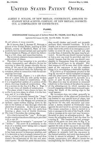
To all whom it may concern:
Be it known that I, ALBERT F. SCHADE, a citizen of the United States, residing at New Britain, Hartford county, State of Connecticut, have invented certain new and useful lmprovements in Jointer~Gage Attachments for Planes, of which the following is a full, clear, and exact description.
This invention relates to planes, and particularly to an improved form of jointer gage attachment therefor, providing means for securely clamping the attachment to the plane body, which means will permit the use of the attachment in connection with various standard makes and sizes of plane bodies irrespective of thickness of the side walls of said bodies or the angle of junction of said side walls with the base of the plane body. Furthermore the clamping means are such that they may be readily moved to either clamping or unclamping position and, when once moved to clamping position, are firmly held in such position. These and other advantages will be more clearly seen from the taken in detailed specification following, connection with the accompanying drawings forming part thereof and showing a preferable embodiment of the invention.
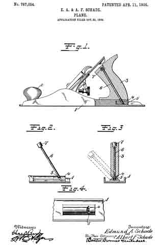
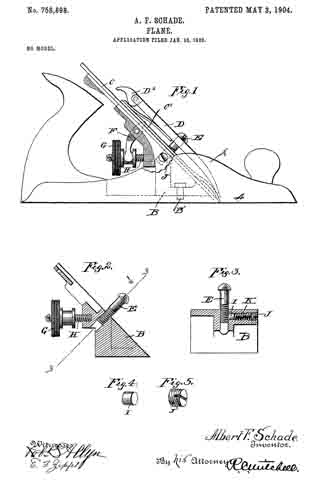
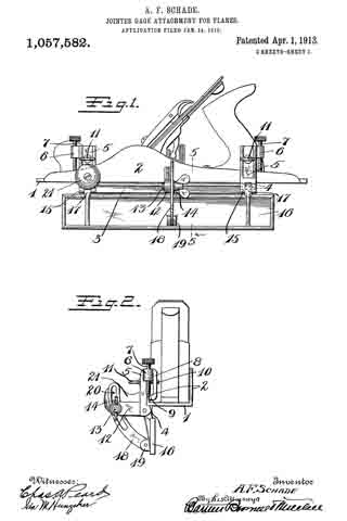
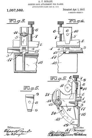
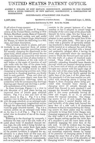
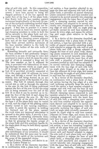
In these drawings, Figure 1 is a view in side elevation of a jack plane having my improved form of jointer gage attached thereto. Fig. 2 is a rear end view of the parts shown in Fig. 1. Fig. 3 is a fragmentary view in elevation, of the plane body with the gage attached, on an enlarged scale. Fig. 4 is a fragmentary longitudinal section through the plane body looking outward toward the gage attached thereto. Fig. 5 is a vertical section on an enlarged scale taken on the line 5–5 of Fig. 1. Fig. 6 is a detailed view in elevation of one of the clamping plates.
Referring to the drawings by numerals, 1 indicates the base and 2 the side walls of a metal plane body of standard channel section type, the side walls 2 being beveled upwardly toward the center from their ends, as is usual in this type of plane. The device of the present invention is adapted for application to a plane body of this type and provides a gage whereby the angle of out may be varied to suit different requirements, such as in joining two parts at an angle. It consists in the present instance of a base member or bar 3 adapted to extend longitudinally of the outer edge of the plane body beneath its lower edge, this bar being provided with inwardly extending flanges 11 adapted to seat against the under face of the base 1 of the plane body. This bar is provided with a plurality of upwardly extending standards 5, these standards being preferably located at or adjacent the ends of the bar and each being provided with a lateral and preferably integral offset 6 having its lower edge positioned above the maximum point to which the forward and rear ends of the side walls of a plane of standard make extend. These offsets are provided with vertically extending threaded bores therein through which are inserted clamping screws 7, the lower ends of which are adapted to be brought into contact with the upper edge of the side wall of the plane body, drawing the flanges 4 of the base bar firmly against the under face of the base 1 of the plane body. The standards 5 of the base member are provided with clamping plates 8 having end flanges 9, these clamping plates being provided with threaded bores therein. A clamping screw 10 extends through an alined bore formed in each standard 5 and engages the threaded bore of its clamping plate 8, this screw preferably having its outer end winged, as at 11, to provide means for manual operation. The clamping screws 10 are of such length that the clamping plates 8 carried thereby will extend inwardly of the plane body beyond the inner face of a side wall 2 of maximum thickness so that by manipulating the clamping screws 10, these plates may be moved outwardly to bring their lower flanges into clamping engagement with the inner face of the side walls 2 of the plane body, their upper flanges resting against the inner face of a standard 5, and the inner faces of the standards engaging the outer face of the side wall. lt will be evident that the base member 3 may be attached to a plane body and held against either lateral or longitudinal movement relatively thereto by means of its plurality of clamping plates 8 which engage the inner face of a side wall of the plane body, and by means of its plurality of clamping screws 7 which engage the upper edge of said side wall. In this connection, it will be noted that once these clamping screws 7 have been moved to bring the flanged portions 4 of the bar against the under face of the base 1 of the plane body, they firmly hold the base member against movement longitudinally of the body by reason of the upwardly extending beveled edges of the side wall 2 with which they are engaged. I find that in practice it is necessary to provide at least two lateral operating clamping members in order to hold the device securely to the plane body and prevent loosening thereof. Furthermore, the provision of the clamping screws adjacent each end of the base member and of the plane body prevent endwise movement of the base member relative to the body by reason of the incline of the side walls of said body.
Extending laterally and outwardly from the base member 3 and preferably integral therewith is an arm 12 having its outer end apertured to receive a bolt 13, upon the outer end of which is mounted a wing nut 14. The base member or bar 3, adjacent its ends, is provided with bifurcations 15 forming bearings between which an angle plate 16 is hinged by means of knuckles 17. A link 18 is provided, pivotally connected at 19 to the angle plate 16 adjacent its lower edge, and having a curved slot 20 formed therein, this slot being formed on an arc with the hinge point of the knuckle 17 as the center. The bolt 13 extends through this curved slot as well as through the aperture in the arm 12, the link 18 being positioned against the face of the arm 12 and the wing nut 14 being mounted over the end of the bolt 18 so that it can be screwed up to engage the face of the link 18 and clamp the same firmly against the arm 12. By this means the angle of the plate 16 relative to the base 1 of the plane body may be varied at will, and the angle of the planing action thereby varied to suit varying conditions. In order to assist the operator in holding the forward end of the plane against the work when my improved attachment is secured to the plane body, I provide a handle member 21 extending outwardly from the forward standard 5 of the attachment so that by grasping the handle proper of the plane body and this auxiliary handle 21, the angle plate 16 may be held firmly against the work.
While I have herein described a preferable embodiment of my invention, it should be understood that the same may be modified within the spirit of the invention and the scope of the appended claims.
What I claim, therefore, and desire to secure by Letters Patent is:
1. In a device of the character described, in combination with a plane body of channel section, a base member adapted to engage the base and adjacent side wall of said plane body, a plurality of spaced clamping plates connected with said base member and adapted to be moved laterally into clamping engagement with the inner face of said side wall, a clamping member carried by said base member and adapted to be moved vertically into clamping engagement with the top edge of said side wall, an angle plate pivotally carried by said base member adjacent its lower edge, and means for adjusting said angle plate relative to its base member.
2. In a device of the character described, in combination with a plane body of channel section, a base bar provided with a plurality of spaced upwardly extending standards adapted to engage the side wall of said plane body and with a flange adapted to engage the base of said plane body, clamping plates connected to said standards and adapted to be moved laterally into clamping engagement with the inner face of said side wall, a plurality of spaced clamping members carried by said base bar adapted to be moved vertically into clamping engagement with the top edge of said side wall, an angle plate hinged at its edge to said base bar adjacent its lower edge, and means for adjusting the angle of said plate relative to said base bar and plane body.
3. In a device of the character described, in combination with a plane body of channel section having the top edges of a side wall inclining upwardly from the ends toward the center, a base member adapted to engage said side wall and the base of said plane body and extending longitudinally thereof, clamping means connected to said member adapted to be moved laterally into clamping engagement with the inner face of said side wall, a clamping screw carried by said base member adjacent the opposite ends thereof and adapted to be moved vertically into clamping engagement with the upwardly inclining top edges of said side wall, an angle plate pivotally connected adjacent its upper edge to said base member adjacent its lower edge, and means for adjusting the angle of said plate relative to said base bar and plane body.
4. In a device of the character described, in combination with a plane body of channel section, a base bar extending longitudinally of the plane body and provided with spaced upwardly extending standards adjacent each end thereof adapted to engage the side wall of said plane body and with a flange adapted to engage the base of said plane body, a clamping plate connected to each of said standards and adapted to be moved laterally into clamping engagement with the inner face of said side wall, offsets from said standards, clamping screws threaded through said offsets and adapted to be moved vertically into clamping engagement with the top edge of said side wall, an arm extending outwardly from said base bar, an angle plate pivoted adjacent its upper edge to said base bar adjacent its lower edge, and connections between said plate and arm whereby the angle of said plate relative to said base bar and plane body may be adjusted.
ALBERT F. SCHADE.
Witnesses:
JOHN DIXON,
ANNA McKEON.
Copies of this patent may be obtained for five cents each, by addressing the “Commissioner of Patents, Washington, D. C.”
_________________