No. 466,494 – Beveling Attachment For Planes (Frank E. Hart) (1892)
[paiddownloads id=”481″]466494


UNITED STATES PATENT OFFICE.

_________________

FRANK E. HART, OF BROOKLYN, NEW YORK.

BEVELING ATTACHMENT FOR PLANES.

_________________

SPECIFICATION forming part of Letters Patent No. 466,494, dated January 5, 1892.
Application filed January 3, 1891. Serial No. 376,605. (No model.)

_________________

To all whom it may concern:

Be it known that I, FRANK E. HART, a citizen of the United States, residing in the city of Brooklyn, county of Kings, State of New York, have invented certain new and useful Improvements in Beveling Attachments for Planes, of which the following is such a full, clear, concise, and exact description as will enable others skilled in the art to which my invention appertains to make and use the same, reference being had to the accompanying drawings, forming part of this specification.

The object of my invention is to provide an attachment for a plane whereby the edge of a board, window-sash, door, or similar article may be reduced to the required angle and an accurate and predetermined bevel given without the aid of a square or other separate measure; and my invention consists in the improvements hereinafter more fully described, and pointed out in the claims.

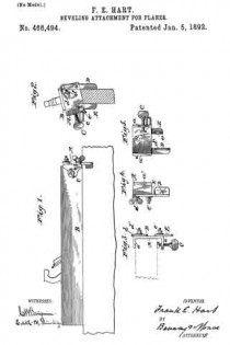
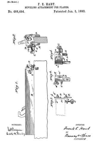
In the drawings, Figure 1 is a view in elevation of an ordinary plane fitted with the improved attachment. Fig. 2 is an end view of the same, showing the plane in action upon a beveled surface. Fig. 3 is a plan view of end of plane with attachment connected, showing top of graduated segment. Fig. 4 is a side view of attachment unconnected, and Fig. 5 is a rear view of the same.

The plate A, having flanges a a’, maybe conveniently secured to the plane B by means of the binding-screw C, and pivoted to this plate are the adjustable guiding arms or bars D and E, extending downward from opposite sides. The arms D and E of course might, if desired, be secured directly to the body of the plane The arm D is preferably formed with a slotted graduated sector d, adapted to be secured by the binding-screw d’, whereby the said arm may be held at any desired angle to the lower surface of the plane, while the arm E is shown as provided with a slotted elbow e, which, moving upon and about the screw e’, permits the arm E to be brought parallel to the arm D and also to approach and withdraw from the same. The lower ends of the guiding-arms D and E are, moreover, preferably provided with flanges d2 e2, which are shown as slightly beveled or inclined, giving thus a greater guiding-surface, while at the same time allowing the necessary oscillation and freedom in the movement of the plane. Further, the flange d2 forms a convenient rest for the finger of the artisan.

It is readily seen that when the guiding-bars D and E are adjusted to any position other than the perpendicular the plane will be made to bear unevenly, cutting more on one side than the other, until A the surface to be smoothed or reduced becomes parallel to the bottom of the plane and its slant or bevel corresponds with the inclination of the guiding-arms.

Having thus fully described my invention, what I claim as new, and desire to secure by Letters Patent, is —

l. In combination with a plane, guiding-arms pivoted thereto and extending downward from opposite sides, said arms being adapted to be secured at an angle, whereby the plane is inclined and made to bear unevenly until the surface acted on is smoothed or reduced to the slant or bevel desired, substantially as set forth.

2. In combination with a plane, a plate adapted to be secured thereto and provided with adjustable guiding-arms extending downward from opposite sides, whereby the plane is inclined and made to bear at an angle, substantially as and for the purpose set forth.

3. In combination with a plane, a plate adapted to be secured thereto, and guiding-arms pivoted to said plate and extending downward from opposite sides, the said arms being provided at their lower ends with beveled fianges, substantially as and for the purpose set forth.

4. In combination with a plane, the flanged plate B and guiding-arms D and E, having graduated sector d and slotted elbow e and flanges d2 and e2, all arranged and secured substantially as described.

FRANK E. HART.

Witnesses:
PERCY GRIFFITH,
WM. J. WINBERG.

No. 434,361 – Plane (Ole O. Skattebo) (1890)

[paiddownloads id=”464″]434361


UNITED STATES PATENT OFFICE.

_________________

OLE O. SKATTEBO, OF HANNAFORD, NORTH DAKOTA,
ASSIGNOR OF ONE-HALF TO JORGEN HANSON, OF SAME PLACE.

PLANE.

_________________

SPECIFICATION forming part of Letters Patent No. 434,361, dated August 12, 1890.
Application filed March 8, 1890. Serial No. 343,098. (No model.)

_________________

To all whom it may concern:

Be it known that I, OLE O. SKATTEBO, of Hannaford, in the county of Griggs and State of North Dakota, have invented a new and Improved Plane, of which the following is a full, clear, and exact description.

My invention relates to improvements in carpenters’ planes; and the object of my invention is to provide a plane that will be equally efficient as a square or bevel plane, and that may be readily converted from one to the other, and also to provide a plane in which a great variety of tools may be inserted, so that the plane maybe used for matching, rabbeting, grooving, rounding, beading, and the like.

To this end my invention consists in a plane constructed substantially as hereinafter described and claimed.

Reference is to be had to the accompanying drawings, forming a part of this specification, in which similar letters of reference indicate corresponding parts in all the figures.

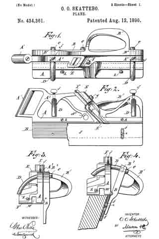
Figure 1 is a plan view of the plane; Fig. 2, a side elevation of the same with a portion of the guide-plate broken away; Fig. 3, an end view of the device as adjusted for a square plane, but with the guide-strip removed; Fig. 4, an end view of the same adjusted for a bevel-plane; Fig. 5, an end view of the plane adjusted for rabbet-work; Fig. 6, a side elevation of one of the separable parts of the plane with a portion of one hinge in section; Fig. 7, a detailed view of the pintle of the plane-hinges; Figs. 8 and 9, side elevations of the strips used for matching and rabbeting; Fig. 10, a transverse section on the line x x, of Fig. 8; Fig. 11, a detail view in elevation of the grooving-knife; Fig. 12, a perspective view of the grooving-guide; Fig. 13, a perspective view of the rounding or molding guide; Fig. 14, a front elevation of a corresponding knife for same, and Fig. 15 a perspective view of a ripping-guide.

The body or frame of the plane consists of two longitudinally-separable parts A and B, which are so hinged together by hinges a, near the ends thereof, that they may be placed at various angles with each other. The hinges a are attached to the inner edge of the part A, which carries the planer-knives, and to the upper edge of the part B, so that when the parts are shut closely together, the part B will shut against theinner edge of the part A, so as to project downwardly at right angles with the same. The hinges a are also provided with a removable pintle b, which fits in the knuckles a’ of the hinges, and which is screw-threaded at the end to engage a similar thread upon the interior of the inner knuckle of the hinges, so that the pintle may be easily removed and the parts A and B of the frame separated.

The parts A and B are each provided with a suitable handle A’ B’, by which the plane may be pushed or pulled, as the case may be, and with upwardly-extending braces A2 and B2, which fit closely together, and which are provided with corresponding holes d, through which extend the curved arms D or straight arms D’, said arms being attached to the braces B2 by the screws e, which fit a screw-thread in the ends of said arms, and being retained in the braces A2 by the binding-screws f which project through from the top of said braces and impinge upon said arms, so that the parts A and B are adjustably connected by the arms D and D’ and their attaching-screws.

In order that there may be no movement whatever between the parts A and B when adjusted by the straight bars, I provide other openings d’ below and between the upper openings d, one of said openings d’ being shown in Fig. 2 and 5. The lower bar D’ passes through said opening d’.

The part A of the frame is provided with the usual slide E, in which a knife F is inserted, with a set-screw g, which projects through the slide and holds the knife in position therein, and with a slot E’, through which the knife extends below the bottom of the plane. The part A is also provided upon the bottom with a longitudinal groove or recess H, which extends the entire length thereof, in which the various guides are inserted, as hereinafter described, and with screws h, which project through the wall of said groove, by means of which the guides are retained in the groove.

Attached to the inner side of the part B is the vertically-adjustable guide-plate J, which is of the same length as the part B and extends below the lower edge thereof. It serves as a guide to the plane, and is attached to the part B of the frame by the screws i, which project through vertical slots j in the plate into the side of the part B, so that by loosening said screws the plate may be easily adjusted upon the frame.

When a square edge is to be planed, the parts A and B of the frame are locked together, so that they will be at right angles with each other, as best shown in Fig. 3, and the plane is used as an ordinary square-edge plane. When a beveled edge is to be planed, the curved arms D are inserted in the holes d, and the parts are swung apart upon their hinges till the desired bevel is obtained, when they are retained in this position by tightening the binding-screws f upon the arms D. This position is best shown in Fig. 4. The plane is then used as an ordinary bevel-plane. To facilitate the adjustment to any bevel, the curved arms D should be marked off into degrees, and then when the proper degree is indicated upon the arms they may be secured in position as desired.

If the plane is to be used as a matching-plane, the guide-strips K and K’, which are of about the width of the groove to be planed, are inserted in the groove H in front of and behind the slot E’. A suitable narrow knife is inserted in the slide E so as to project down between the guide-strips K and K’, and the plane is used as an ordinary matching-plane. If a tongue is to be cut, the guide-strips K and K’ are removed and a suitable knife for tongue-planing inserted in the slide E.

If the plane is to be used as a rabbet-plane, the curved arms are removed from the holes d and the straight arms D’ inserted, the pintle b is removed from the hinges a, and the plane will then be laterally adjustable. The arms D’ are held in a desired position by the binding-screws f in the same way that the arms D are secured, and the arms should be marked off into fractions of an inch, that they may be easily adjusted. The guide-strip K’ and the guide-strip K, which is provided with a vertically-adjustable knife l, which is attached thereto by a screw m, projecting through a slot l’ thereof, are inserted in the groove H and held by the screws h. A suitable knife is inserted in the slide E, and the plane is ready for rabbet-work. In using it as a rabbet-plane and for other similar work the distance of the knife from the edge of the board is regulated by the arms D’ and binding-screws f as the part B of the frame, which extends down the side of the board, may be brought as near to the part A as desired, and is secured in that position, as described. When used for rabbet-work, the knife l will project a desired distance below the guide-strip K, and, entering the board to be planed, will cut a smooth surface for the shoulder of the rabbet.

In Figs. 11 and 12 I have shown a knife and guide for grooving. The guide L is provided with an upwardly-projecting tongue L’, which fits into the groove H of the plane, is held therein by the screws h, and is provided with a rounding lower face corresponding with the groove to be planed. The knife L2 has a convex edge corresponding to the shape of the lower surface of the guide L. It is inserted in the slide E of the plane in the usual manner, and the plane is used as an ordinary grooving-plane.

In Figs. 13 and 14 I have shown a knife and guide for rounding or molding. The guide M is provided with a tongue M’ which fits the groove H, and which is used in the same way as the grooving-guide. The rounding-guide, however, is provided with a concave lower surface and the plane with a corresponding knife M2, having a concave cutting-edge.

When the plane is to be used as a ripping-plane, the ripping-guide N, having a narrow edge N’, is secured in the groove H, a suitable ripping-knife is inserted in the slide E, and the plane is used as a ripping-plane.

I might show many more tools that could be used with the plane; but without going further into details it is evident that by making a suitable guide to fit the groove H and providing a corresponding knife the plane may be used to produce almost any form.

It will be seen from the foregoing description that a person by having a plane as described, with the accompanying guides and knives, can do the work now performed by a great many separate planes.

Having thus described my invention, what I claim as new, and desire to secure by Letters Patent, is —

1. A plane consisting in a stock or knife-carrying portion, a longitudinal guide adapted to be held parallel with or at any desired angle to the said stock, a separable hinge-joint to connect the two parts when the guide is to be held at an angle, and interchangeable rods and set-screws for holding the guide parallel with or at an angle to said stock, substantially as set forth.

2. A plane consisting, essentially, of two longitudinally-separable parts, the knife-carrying part having a longitudinal slot in the bottom thereof, in which any desired form of guide maybe inserted, and having a suitable slide in which a knife may be secured to match said guide, substantially as described.

3. The combination, with the plane A B, the part A having a longitudinal groove in the bottom thereof, as shown, of the rabbet-guide K, adapted to fit in said groove, and having a vertically-adjustable knife l affixed thereto to cut the shoulder of the rabbet, substantially as described.

OLE O. SKATTEBO.

Witnesses:
MARTIN MOSSING,
ERIK AUSTAD.

No. 19,620 – Joiner’s Beveling Plane (T.A. Chandler) (1858)

[paiddownloads id=”73″]19620


UNITED STATES PATENT OFFICE.

_________________

T. A. CHANDLER, OF ROCKFORD, ILLINOIS.

JOINER’S BEVELING-PLANE.

_________________

Specification of Letters Patent No. 19,620, dated March 16, 1858.

_________________

To all whom it may concern:

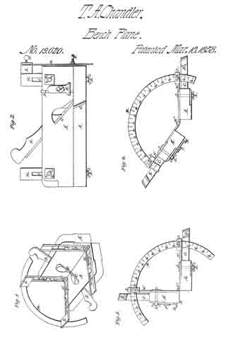
Be it known that I, T. A. CHANDLER, of Rockford, in the county of Winnebago and State of Illinois, have invented a new and Improved Bevel-Fillister and Rabbet-Plane Combined; and I do hereby declare that the following is a full and exact description thereof, reference being had to the accompanying drawings, in which —

Figure 1 is a perspective view; Fig. 2, a side view, and Figs. 3 and A end views. Like letters designate like parts in the several views.

The two planes A, and A’, separately considered, correspond to a rabbet plane, provided with keys B, and plane irons C, in the ordinary manner. Molding planes in some instances may be substituted. The cutter D, gage E, and set screw F, are attached to the side of the plane, in the usual way, and for the ordinary use. The two planes are connected together by the jointed slides H, and H’, Figs. 1 and 2. These slides fit into corresponding grooves or gains in the side of the planes so that the slides will be flush with the side of the planes. In the slides are elongated slots I, which receive the shank of the bolts J, which shank passes through the plane, and has a thumb screw K, on the opposite side as seen in Figs. 2 and 3. In each slide is an elongated recess or depression, which receives the bolt head as represented at L, Figs. 1 and 2. The slides being thus formed and provided with a hinge joint at H”, allows the planes to be moved to any position or angle upon the slides, and secured in place, by the bolts and thumb screws J, and K.

From the slide H”, extend two arms, L, L, in the outer ends of which are slots to receive the sector M, as shown in Figs. 1, 3, and 4. The set screws N, N, enter the slots, for the purpose of holding the sector in place, and thereby the planes, in the desired position or angle. By means of the degrees indicated on the sector, the planes may be set so as to cut at any desired angle.

The planes may be moved so as to cut at various angles, and may be reset so as to cut at any previous form of angle, by noting the degree on the sector. The planes may be set at right angles so as to have the character of a fillister plane, for cutting grooves. By extending one plane from the other, at right angles, they form a raising plane, for cutting or raising panels. By turning them at an acute angle, they become a bevel plane. By placing the planes at right angles so that the face of one plane will be level with the side of the other, similar to the position of Fig. 3, they become a halving plane. By extending one plane from the other so that one is set at an obtuse angle to the other, similar to the position of Fig. 4, they will bevel moldings for pilasters and other similar purposes. The plane may be made to cut moldings at other angles than those described, and may be set in various other positions than those described, which positions will readily be suggested in the practical operation of the plane, and will not change the nature of my invention.

By making slots in the arms of the hinges H, H, and fastening them to the plane stocks by thumb screws, so that they can be adjusted, and fastened in the position desired, the plane can be adjusted to plane flat bevels, or bevels of a small angle on boards of various thickness on both sides of the board at the same time, which cannot be done with any plane made prior to my invention.

Having described my invention so as to enable any person skilled in the art to make and use it, I claim —

Making one or both plane stocks adjustable, on the arms or shanks of the hinges, so as to plane bevels of the same angle, on boards of various thicknesses substantially as described.

THOS. A. CHANDLER.

Witnesses:
W. H. BURRIDGE,
JAMES A. BRIGGS.

No. 31,707 – Bevel Attachment For Bench Planes (Leonard O. Fairbanks) (1861)

[paiddownloads id=”91″]31707


UNITED STATES PATENT OFFICE.

_________________

LEONARD O. FAIRBANKS, OF NASHUA, NEW HAMPSHIRE.

BEVEL ATTACHMENT FOR BENCH-PLANES.

_________________

Specification of Letters Patent No. 31,707, dated March 19, 1861.

_________________

To all whom it may concern:

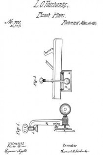
Be it known that I, LEONARD O. FAIRBANKS, of the city of Nashua, county of Hillsboro, and State of New Hampshire, have invented a new and useful Square and Bevel Attachment for Planes or other Bench-Tools; and I do declare the following is a fulland exact description thereof, reference being had to the annexed drawings.

The object of my invention is to enable persons using the ordinary bench planes to produce a square or any required bevel with certainty and despatch, Without the extraneous aid of square and bevels.

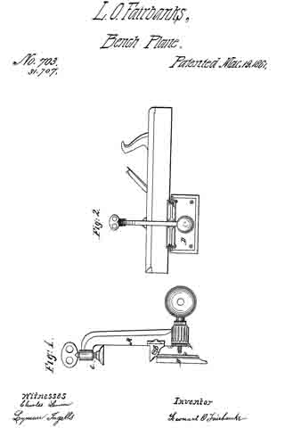
The nature of my invention consists in attaching to bench planes a clamp with an adjustable guide, and is constructed as follows: I construct a clamp A, Figure 1, of such size as will readily receive between its lugs B and binding screw C the diliierent sizes of planes, in such a manner that will secure the plane of the lugs in the square of the plane, as shown in perspective (Fig. 2). To the lugs is connected a guide plate D whose proportion is such as to secure the steadiness of a guide. At the foot of the upright A and at right angles with the face of the guide D is an adjjusting screw H which is operated by a stationary nut F. When the clamp is attached to the plane the guide plate is adjusted either at right angles with the plane stock, for the purpose of obtaining a square edge, or set at any required angle, for a bevel, by means of the adjusting nut F.

What I claim as my invention and for which I desire to secure Letters Patent is —

The attaching of an adjustable guide to the stocks of bench planes, substantially in the manner and for the purpose set forth.

LEONARD O. FAIRBANKS.

Witnesses:
O. D. MILLER,
ISAAC SPALDING.

No. 8,655 – Beveling Plane (Harrison W. Lewis) (1852)

[paiddownloads id=”8″]8655


UNITED STATES PATENT OFFICE.

_________________

HARRISON W. LEWIS, OF BATH, NEW YORK.

BEVELING-PLANE.

_________________

Specification of Letters Patent No. 8,655, dated January 13, 1852.

_________________

To all whom it may concern:

Be it known that I, HARRISON W. LEWIS, of Bath, in the county of Steuben and State of New York, have invented a new and useful Improvement in Beveling-Planes; and I do hereby declare that the following is a full and exact description of the same, reference being had to the annexed drawings, making part of this specification, in which —

Figure 1 is a front elevation; Fig. 2 is a central longitudinal section; Fig. 3 is an end view from the left; Fig. 4 represents the rear side of the guard, and Fig. 5 shows the form of one of the planing cutters.

This invention consists of a plane, or planing instrument, of peculiar form, and furnished with several peculiar devices, so as to be adapted to the purpose of forming at one operation, and with extraordinary accuracy, a double bevel upon the grooved edge of a stile or rail of a panel door.

The stock A of this plane, has a longitudinal groove in the center of the under side thereof; and the spaces between this groove and the sides of the stock, consist of two inclined planes (surfaces) a a, the two planes being at an angle of about eighty degrees with each other, or about fifty degrees (each) with the sides of the stock. The stock is furnished with two cutters B (see Fig. 5) the cutting edges of which conform to the obliquity of the plane surfaces a a, and are fastened by wedges (b) in the manner of common planing tools.

An adjustable vertical guide C passes through the stock between the two cutters, and is secured in the required position by a horizontal screw c; and in the bottom of the guide is a narrow horizontal groove to receive the back of the gage-bar D. This gage-bar extends the full length of the stock A, and the two ends thereof are bent upward, as shown at e e Fig. 2. The forward end of the gage-bar passes up through a vertical groove in left or forward end of the stock (or in a vertical plate attached to the end of the stock), and has a slot (i) through which passes a set screw a whereby the gage-bar is held in the required position. The rear end of the gage-bar enters a vertical groove in the right end of the stock, and is held fast by a set-screw r, which passes through a plate s which is attached to the right end of the stock.

Two horizontal guard-screws E E pass through the stock, near the two ends thereof; and each guard-screw is furnished with a nut F and a collar G, whereby the screws are adjusted in any required position. The front end, or head, of each guard-screw has a shoulder or downward projection t, to the bottom of which is attached one end of a guard-stock H; and to the rear side of the guard-stock, an adjustable guard I is attached by means of two set-screws u u, which pass through two vertical slots v v, (Fig. 4) in the guard, and extending through the guard-stock, the front ends thereof are furnished with thumb-screw nuts x x. The slots v have rebates in the sides thereof (see Fig. 4) to receive the square heads of the screws u, that the heads may not be prominent to the face of the guard.

When the grooved edge of a rail is to be beveled by this plane, the guard is so adjusted as to slide upon the face of the rail, while the bottom of the guide C slides within the groove of the rail; and the gage-bar is so adjusted as to come in contact with the bottom of the said groove when the rail is sufficiently beveled, and thus prevent the cutters from planing off too much.

What I claim as my invention and desire to secure by Letters Patent is —

1. The adjustable gage-bar (D) and the vertical adjustable guide (C), in combination with the double faced plane-stock, all constructed and relatively arranged as herein described.

2. The combination of the guard-screws (E) , guard-stock (F), adjustable guard (I), gage~bar (D), vertical guide (C) and plane-stock (A; the whole being constructed and arranged substantially in the manner and for the purpose herein set forth.

HARRISON W. LEWIS.

Witnesses:

JOHN L. SMITH,
RUFUS PORTER.

No. 6,304 – Plane For Bevel Edges (William H. Blye) (1849)

[paiddownloads id=”2″]6304


UNITED STATES PATENT OFFICE.

_________________

WILLIAM H. BLYE, OF DE RUYTER, NEW YORK.

PLANE FOR BEVEL EDGES.

_________________

Specification of Letters Patent No. 6,304, dated April 10, 1849

_________________

To all whom it may concern:

Be it known that I, WILLIAM H. BLYE, of De Ruyter, in the county of Madison and State of New York, have invented a new and useful Improvement in Planes for Working in Wood, of which the following is a full and exact description, reference being had to the annexed drawings of the same, making part of this specification, in which —

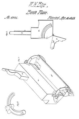
Figure 1 is a perspective view, Fig. 2. is an end elevation, and Fig. 3 is a view of the graduating arm or brace, and the guard plate, which secures the same to the end of the plane stock.

The same letters refer to the same parts in all the figures.

The nature of my invention, and improvement consists, in attaching an adjustable hinged guard or fence, to rabbet, fillister, molding, or other planes, by means of which the workman is enabled to bevel the edges of a piece of wood, in a uniform manner, and at any given angle.

In the accompanying drawings (a) represents the plane-stock which is made of wood, and of any required form and size.

(b) is the plane iron, (c) the wedge, which holds the iron in its place, (d) the guard or fence, is of the same length as the stock, and has one plane side which is about the same width as the face of the plane. From its uipper edge a rib (d2) is placed, for the purpose of stiffening the guard, and supporting the outer end of the braces, the outer, and under side of the rib and the lower edge, and back of the guard, may be ornamented with moldings, as represented, or otherwise, or may be left plain, according to the taste of the constructor: this guard is joined to the stock by hinges (e, e) which allow it to turn through an arc of about 100°, which admits of sufficient variation for most purposes, but in any case where greater variation, in the adjustment may become necessary, the hinges, and other parts concerned, can be so constructed, and arranged, as to allow the guard to turn through a longer arc. The braces (g) are of metal, and in the form of segments of a flat ring whose center is the axis of the hinge, the outer end of these braces have slots in them, through which the thumb screvv (h passes into the ends of the guard, to clamp it to the brace, these slots, also admit of the guard being turned to any extent within the limits of their length, to change the angle at which it stands to the face of the plane, and when the slots are too short, to admit of all the variation required, the ends of the braces are drawn out of the hole, formed in the end of the plate (i) and in the wood under the plate, and when placed in the proper position they are clamped firmly by the thumb screws (k k). Graduated scales of degrees may be formed upon the braces to denote the angle at which the guard may be placed.

The several parts of the plane above described may be made of wood, or metal, and arranged in a great variety of ways, without departing from the principle. of the invention, but these several modes, consist of devices well known to mechanics, and I therefore deem it unnecessary here to describe them.

The operation of this plane, is similar to that of others, the guard being adjusted to the required angle, is placed against the side of the piece, and held there firmly while the face of the plane is applied to the edge of the piece of wood, being pressed down upon it and at the same time pushed forward, the edge of the iron penetrates the wood to the depth which it projects through the face of the plane, and removes a shaving of that thickness — this operation is repeated until the piece is reduced to the required form.

What I claim as my invention and desire to secure by Letters Patent is,

The manner herein described of planing the edges of pieces of wood of a beveled form at given uniform or varying angles, by means of an adjustable guard hinged to the plane stock.

In testimony whereof I have hereunto signed my name.

WILLIAM H. BLYE.

Witnesses :
Z. T. BENTLEY,
A. V. BENTLEY.

No. 11,235 – Beveling Plane (Wheeler, Rogers, Pierce & Tidey) (1854)

[paiddownloads id=”13″]11235


UNITED STATES PATENT OFFICE.

_________________

M. J. WHEELER, G. W. ROGERS, H. W. PIERCE AND M. B. TIDEY, OF DUNDEE, NEW YORK.

BEVELING-PLANE.

_________________

Specification of Letters Patent No. 11,235, dated July 4, 1854.

_________________

To all whom it may concern:

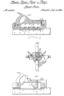
Be it known that we, M. J. WHEELER, G. W. ROGERS, H. W. PIERCE, and M. B. TIDEY, of Dundee, in the county of Yates and State of New York, have invented certain new and useful Improvements in Beveling-Planes; and do not hereby declare that the following is a full, clear, and exact description of the same, reference being had to the accompanying drawings, forming part of the specification, in which–

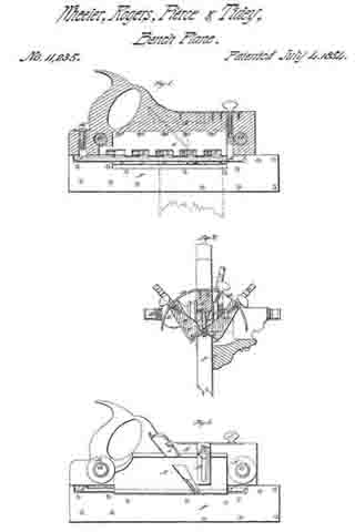
Figure 1, is a longitudinal section taken directly through the center of the body of a plane, constructed according to our invention. Fig. 2, is a side view.

Similar letters of reference indicate corresponding parts in the several figures.

The object of this invention is to plane a double bevel, or in other words, to plane two faces at any desired angle to each other and to a third face.

The invention consists in attaching the two cutters which are to plane the two faces to two wings which are both hinged or otherwise attached to the body of the plane, so as to swing around a common axis, and each of which is adjustable and capable of being secured in any position, independently of the other, so as to bring and set the faces of the cutters at any angle to each other or to the fence which is employed to guide the plane.

To enable those skilled in the art to make and use our invention, we will proceed to describe its construction and operation.

A, is the body of the plane.

B, B, are the wings which contain the cutters, f, f, and are connected to the under side of the body, A, by a three flanged hinge, c, c, c’, which is best illustrated in Fig. 2. One flange, c’, of this hinge is inserted into the body, A, and secured by screws, d, d. The screws, c, c, are secured, one to each of the faces of the wings, B, B, and all are united by a pin, e, running the whole length of the wings. The wings are shorter than the body, A, and a recess, g, (see Fig. 2), equal in length to the wings, is cut in each side of the latter, to allow them to lie close up to the sides of it and bring their faces and the edges of their cutters as nearly as is desirable in the same plane. The cutters are of the usual form and secured in the wings by wedges, O, ), in the usual way. The wings swing within a bar, D, which is in the form of part of a circle described from the pin or axis, e, and are secured in any position by means of set screws, E, E, passing through slots in the bar, D, and screwing into their backs, as shown in Fig. 2. The upper surface of the bar, D, is graduated in degrees, commencing in both directions from the sides of the body, A, in order to enable the faces of the wings to be set at any desired angle.

F, is the fence having the screws, G, G, firmly attached to it, perpendicularly to its face. Said screws pass through holes in the body, and being furnished on one side thereof with a nut, H, and on the other side with a follower, I, to adjust the fence to the body and wings, for the purpose of planing stuff of various widths.

K, is the depth gage which is adjusted by means of the screws, L, and M, for the purpose of enabling the tool to cut to the required depth to perfect the bevel and no farther.

The operation of the plane can be best explained by illustrating the beveling of a door stile on opposite sides of the channel, which receives the panel. The stile, P, is represented in Fig. 2. The fence, F, is adjusted by the screws, G, G, to bring the depth gage to the proper distance from the side of the stile. The wings are adjusted to set the edges of the cutters at the proper angle to each other and to the face of the stile, and the depth gage is set to the proper depth. The edge of the stile is then planed down till the depth gage comes in contact with the bottom of the groove.

If it be desired, the two sides of the channel may have different bevels, as each wing, with its cutter, is adjustable independently of the other.

By making the edges of the cutters of this plane of proper form coves, ovolos, ogees, or moldings of any other form may be produced on the edges of the stuff.

What we claim as our invention, and desire to secure by Letters Patent, is:–

Attaching the two bevel cutters, f, f, to two wings, B, B, which are hinged by a three flanged hinge, c, c, c’, or otherwise so secured to the body, A, of the plane, as to be capable of swinging a certain distance around a common pivot or axis, e, for the purpose of being adjusted to set their faces and the edges of their cutters at any angle to each other and to the face of the fence, F.

M. J. WHEELER.
G. W. ROGERS.
H. W. PIERCE.
M. B. TIDEY.

Witnesses:
S. S. BENHAM,
H. CHURCH.