No. 913,959 – Scraper (Noble Keller) (1909)

[paiddownloads id=”658″]913959


UNITED STATES PATENT OFFICE.

_________________

NOBLE KELLER, OF LOS ANGELES, CALIFORNIA.

SCRAPER.

_________________

913,959. Specification of Letters Patent. Patented March 2, 1909.
Application filed January 10, 1908. Serial No. 410,191.

_________________

To all whom it may concern:

Be it known that I, NOBLE KELLER, a citizen of the United States of America, residing at Los Angeles, in the county of Los Angeles, State of California, have invented a certain new and useful Scraper; and l do hereby declare the following to be a full, clear, and exact description of the invention, such as will enable others skilled in the art to which it appertains to make and use the same.

This invention relates to a scraper and has among other objects, to provide a tool of this description, of simple and cheap construction which shall be efficient and durable in use and wherein the cutting blade can be readily formed, without the use of tools, other than those usually possessed by the user of the device.

It is also an object to provide a scraper that can be worked close up to any projection perpendicular to the surface on which it is used.

Another object is to provide means for easily adjusting the scraper blade.

A further object is to provide a scraper of such form that it can be readily grasped and pressure applied thereto without fatiguing the hands of the operator.

Still another object is to provide a scraper in which the blade need not be removed to sharpen the same.

One form in which this invention may be embodied, is herein described and is illustrated in the accompanying sheet of drawings, in which —

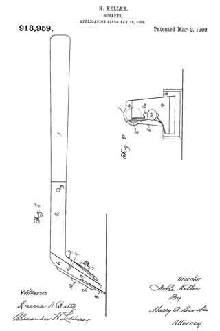
Figure 1 is a side elevation, and Fig. 2 is a rear elevation with portions broken away.

A handle 1 is fitted into a tubular socket 2, being retained therein by a pin or rivet 3. The rearward end of socket 2 has a downwardly deflected flattened portion 4, to which is attached by screws 5, a bolster 6, prefer-
ably formed of wood or other slightly yielding material. The lower portion of bolster 6 has a rabbet 7, which receives the upper portion of a blade 8, said blade being held frictionally between bolster 6 and a back plate 9, by means of bolt 10, which passes through a slot 9a in back plate 9, bolster 6, and downwardly deflected portion 4 of the handle, and has on its forward end, a nut 11. The sides of blade 8 may be beveled and sharpened in the same manner as the bottom of said blade. Blade 8 is preferably wider than back plate 9 and bolster 6. It may be formed of any convenient piece of sheet metal, such as an old saw blade, and there being no holes through it, it can readily be made with such tools as are usually carried by a wood worker.

The mode of operation of this invention is as follows: Handle 1 is grasped by one hand of the operator, while the other hand rests upon the top of bolster 6 and back plate 9. These parts being designed as shown, the hand rests easily upon this portion of the assembled tool and pressure may be applied without great fatigue to the operator.

The scraper is used by drawing it along the surface to be scraped, in the usual manner, as will be readily understood by those skilled in the art to which this invention appertains. In working close to vertical surfaces, the scraper may be laid upon its side and the ends of the blade used. In such use of the device, it will be readily understood that the handle extends away from the vertical surface, so that there is a sufficient clearance to enable the operator to manipulate the device conveniently. The blade 8 may be protruded, as it becomes worn, by striking on the upper sides of the projecting portions.

I claim:

1. A scraper comprising ahandle having a widened portion at the lower end thereof, a wooden bolster affixed to said portion, a back plate, said bolster and said plate suitably shaped to afford a hand-rest thereon when the same are assembled, a single bolt having a nut threaded thereon and passing through said plate, bolster, and widened portion of the handle, whereby the blade may be clamped between said bolster and said back plate.

2. A scraper comprising a handle, a metal tube affording a socket for said handle and having a flattened part bent at an angle to said socket, a wooden holster secured to said flattened part, said bolster shaped to afford a hand-rest thereon, and having a out-away portion to accommodate a blade, a slotted back plate, a single bolt having a nut threaded thereon and passing through said plate, bolster, and flattened part, whereby the blade may be clamped between the bolster and the back plate.

In testimony whereof, I have signed my name to this specification in the presence of two subscribing witnesses at Los Angeles county of Los Angeles, State of California this 31st day of December A. D., 1907.

NOBLE KELLER.

Witnesses:
ALEXANDER H. LIDDERS,
ANNA A. BALTZ.

No. 842,275 – Scraper (Justus A. Traut) (1907)

[paiddownloads id=”638″]842275


UNITED STATES PATENT OFFICE.

_________________

JUSTUS A. TRAUT, OF NEW BRITAIN, CONNECTICUT, ASSIGNOR TO STANLEY RULE & LEVEL COMPANY,
OF NEW BRITAIN, CONNECTICUT, A CORPORATION OF CONNECTICUT.

SCRAPER.

_________________

842,275. Specification of Letters Patent. Patented Jan. 29, 1907.
Application filed March 8, 1906. Serial No. 304,937.

_________________

To all whom it may concern:

Be it known that I, JUSTUS A. TRAUT, a citizen of the United States, residing at New Britain, Hartford county, Connecticut, have invented certain new and useful Improvements in Scrapers, of which the following is a full, clear, and exact description.

My invention relates to improvements in scrapers.

The object is to facilitate adjustment of the parts and improve the construction so that it may be adapted to use under many different circumstances. I have sought to construct the parts so that they may be manufactured readily and assembled or taken apart without difficulty.

The preferred form of the invention is shown in the accompanying single sheet of drawings, in which —

Figure 1 is a side view of the scraper embodying the improvements of my invention. Fig. 2 is a front view of the same. Fig. 3 is a rear view of the scraper with the handle shown in section. Fig. 4 is a rear view of the back member of the head. Fig. 5 is a side view of the same. Fig. 6 is a plar view of a fragment of the handle.

The handle is preferably formed in two portions — a grip member 1 and a body member 2.

The head of the scraper carries the blade 3 and is preferably provided with an auxiliary grip or handle 4.

5 and 6 are the front and rear members, respectively, of the head, between which the blade is clamped.

7 is a screw located between the upper and lower ends of the plates 5 6. This screw passes freely through plate 5 and takes into plate 6, so as to produce, in effect, a hinged joint which may be adjusted to and fro to vary the widths of the space between plates 5 6.

8 8 are screws arranged at opposite edges of the plate 6 and screw-threaded therein. The ends of these screws project into cavities in the opposite face of the member 5, but are not screw-threaded therein. The function of these screws is to preserve the alinement of plates 5 6 and to act as spacers to guarantee the substantial parallehsm of said plate, whereby the ready substitution of blades 3 is permitted. The screws 8 8 also perform a stop function, the upper edge of the blade 3 taking a bearing against said screws so that blade will be projected uniformly from the clamping-jaws. These “stop-screws” 8 8, as we shall term them, may be shifted up or down on plate 6, there being a series of screw-holes a ong opposite edges thereof to permit this shifting of the screws to be made. By this means when blade 3 wears down or if a short blade is to be substituted the screws 8 8 may be moved to any one of the holes 8’, 82, or 83, so as to adapt the holder to the particular blade to be used.

9 is a main adjusting-screw having a stop-head whereby it may be easily operated. When approximate adjustment of the plates 5 6 has been secured by the adjustment of screws 7 and 8 and the blade inserted, the user may set up on screw 9 in such a manner as to powerfu ly clamp the blade 3. The rear of the back member 6 of the head is provided with a pair of lugs 10 10, to which the handle is pivoted.

11 is a curved arm extending from the rear of the back member and provided with a curved slot. This arm is preferably formed pf a separate piece of metal and riveted to the lug 12.

13 is a screw preferably provided with an enlarged head for engagement by the thumb and finger and by means of whic the handle is clamped to the arm 11. By this means the angle which the blade makes relative to the handle may be readily varied to suit the conditions under which the scraper is to be used. The parts, however, when clamped together are rigid, so that there is practically no vibration possible when the tool is in use.

What I claim is —

A scraper comprising a head portion formed of two parts, means for adjustably connecting the same at an intermediate point, said connection permitting said parts to swing, jaws formed by the edges of said parts at one slde of said connection, a clamp-screw at the opposite side of said connection, said clampmg-screw passing through one part and bearing against the other, and adjustable stop-screws at the opposite slde edges of said parts, and a handle hinged to one of said parts and means for adjusting the angle of said handle relatively thereto.

JUSTUS A. TRAUT.

Witnesses:
W. J. WORAM,
H. S. WALTER.

No. 740,087 – Scraper (John W. Carleton) (1903)

[paiddownloads id=”591″]740087


UNITED STATES PATENT OFFICE.

_________________

JOHN W. CARLETON, OF NEW BRITAIN, CONNECTICUT.

SCRAPER.

_________________

SPECIFICATION forming part of Letters Patent No. 740,087, dated September 29, 1903.
Application filed September 18, 1902. Serial No. 123,870. (No model.)

_________________

To all whom it may concern:

Be it known that I, JOHN W. CARLETON, a citizen of the United States of America, residing at New Britain, in the county of Hartford and State of Connecticut, have invented certain new and useful Improvements in Scrapers, of which the following is a specification.

The embodiment of the invention illustrated and described herein is in the form of a scraper for use in scraping floors, &c.

The object of the invention is to permit of a wide adjustment of the handle with respect to the blade.

It is clear that the invention is applicable to other uses than to scrapers.

Referring to the drawings, Figure 1 is a side view of a scraper. Fig. 2 is a front view of the same. Fig. 3 is a rear view. Fig. 4 is a top view with part of the hand-rest broken away.

Referring to the drawings, A denotes the blade; B, a clamping-head having on one side a threaded pin C, which projects through a hole in the blade and is engaged by the thumb-screw D, which bears on a washer E. The rear of the clamping-head B has the lug F, one side of which is milled, as at f in Figs. 3 and 4. The handle G is provided with a disk H, one face of which is milled to fit the milling on the lug F. The handle is held to the lug by the pin J and the thumb-nut K. On the upper edge of the plate is located a hand-rest M, to which is secured a strap N, which enters a recess in the washer E to prevent the hand-rest from slipping side-wise off the blade. It is readily seen from the drawings that the handle is capable of adjustment in a plane at right angles to the blade by turning it on the pin J and securing it in place by the thumb-nut K, also that it is adjustable in a plane parallel to the blade by turning the handle and the clamping-head B about the axis of the pin C and maintaining it in position by means of the thumb-nut D. Thus I am enabled to so adjust the handle of the scraper that it may be used under any and all conditions — as, for instance, against the base-board when scraping a fioor. I am aware that other devices have been produced for accomplishing this object; but they are expensive to manufacture. They are difficult of adjustment.

The device herein shown and described is very inexpensive to manufacture and can be readily adjusted and used by any one.

I claim as my invention —

In combination with the clamping-head, a lug carried thereby, a pin oppositely disposed on said lug, and a handle adjustably connected to said lug, a blade mounted on said pin, a washer engaging the outer face of said blade, a locking means frictionally engaging the said washer, a hand-rest carried by the blade, and a strap carried by the said hand-rest and engaging a recess in the said washer, substantially as and for the purpose specified.

In testimony whereof I affix my signature in presence of two witnesses.

JOHN W. CARLETON.

Witnesses:
J. E. COOPER,
ANNA C. MALMFELDT.

No. 182,881 – Improvement In Box-Scrapers (Leonard Bailey) (1876)

[paiddownloads id=”270″]182881


UNITED STATES PATENT OFFICE.

_________________

LEONARD BAILEY, OF HARTFORD, CONNECTICUT.

IMPROVEMENT IN BOX-SCRAPERS.

_________________

Specification forming part of Letters Patent No. 182,881, dated October 3, 1876; application filed September 13, 1876.

_________________

To all whom it may concern:

Be it known that I, LEONARD BAILEY, of Hartford, in the county of Hartford and State of Connecticut, have invented certain new and useful Improvements pertaining to a Box-Scraper, of which the following is a specification, reference being had to the accompanying drawings, where —

Figure 1 is a side view. Fig. 2 is a top view. Fig. 3 is a bottom view. Fig. 4 is a top view, chisel removed. Fig. 5 is a central section on plane x x, Fig. 2, chisel removed.

The letter a denotes a forked handle, whereby to move the scraper back and forth. b denotes a rod, which is at once a pivot-bar for head c and a front rest for chisel d. The back side of the pivoted head c is obliqued, to form a bed for the chisel, which chisel is held in place by thumb-screw e running up through the bed elongation c’ from the back side, and bearing against the back side of the chisel.

The throat f may be made larger or smaller, and the out of the chisel correspondingly increased or decreased by manipulation of the guard or gage i, pivoted by its side arms i1 on the rod b, given a closing tendency by the spring-bar i2, and opened against this tendency by the thumb-screw g.

The features of invention, specified in the first two clauses of the following claim, are applicable as well to spokeshaves as to box-scrapers.

I claim as my invention —

1. In combination, head c, having bed elongation c’, chisel d, front rest b, and thumb-screw e passing through the bed elongation and pressing on the back side of the chisel, all substantially as shown and described.

2. In combination, bar b, head c, chisel d, guard or gage i pivoted on bar b, spring-bar i2, and screw g, all substantially as shown and described.

3. In combination, forked handle a, bar b, serving as pivot for head c and front rest for chisel d, pivoted head c having elongation c’, and screw e, all substantially as shown and described.

LEONARD BAILEY.

Witnesses:
ROBT. F. GAYLORD,
CHAS. BUCKLAND.

No. 175,758 – Improvement In Box-Scrapers (Henry Richards And Justus A. Traut) (1876)

[paiddownloads id=”260″]175758


UNITED STATES PATENT OFFICE.

_________________

HENRY RICHARDS AND JUSTUS A. TRAUT, OF NEW BRITAIN, CONNECTICUT.

IMPROVEMENT IN BOX-SCRAPERS.

_________________

Specification forming part of Letters Patent No. 175,758, dated April 4, 1876; application filed March 13, 1876.

_________________

To all whom it may concern:

Be it known that we, HENRY RICHARDS and JUSTUS A. TRAUT, of New Britain, in the county of Hartford and State of Connecticut, have invented certain new and useful Improvements in Box- Scrapers; and we do hereby declare the following to be a full, clear, and exact description of the invention, such as will enable others skilled in the art to which it pertains to make and use it, reference being had to the accompanying drawings, which form part of this specification.

The nature of our invention consists in the construction and arrangement of a box-scraper, which is fully illustrated in the accompanying drawing.

A represents the shank of the tool-scraper fastened in the handle B at one end, and at the other end the shank forms two prongs, A’ A’, between which the head C is pivoted. The head is perfectly smooth and flat, with two side flanges, C’ C’, on its upper side, to which the prongs A’ of the shank are pivoted. On the upper side of the head C at the front are formed two parallel inclined ribs or flanges, a a, upon which the knife D rests, the edge of the knife projecting through a slot, b, in the head somewhat in the same manner as the blade of a carpenter’s plane. Between the upper ends of the side flanges C’ of the head is pivoted a jaw, E, having a set-screw, G, passed through its upper end. This screw bears against the upper portion of the knife or blade D, forcing the lower portion of the jaw also against the same, and holding the blade firmly and securely against the ribs or flanges a. The blade can easily and quickly be adjusted as required, and also be taken out for sharpening.

It will be noticed that the head rocks or oscillates between the prongs A’, and thus the scraper adapts itself to any position of the box and operator.

We are aware that a pivoted handle has been applied to planes for the purpose of pushing them along, and this we disclaim. We pivot our handle to the head for the purpose of drawing the scraper along, and allowing the head to accommodate itself to different surfaces.

Having thus fully described our invention, what we claim as new, and desire to secure by Letters Patent, is —

In a box-scraper, the combination of the handle B, pivoted to the head C, jaw E, blade D, set-screw G, and suitable rests for the blade, substantially as shown and described.

In testimony that we claim the foregoing we have hereunto set our hands this 3d day of March, 1876.

HENRY RICHARDS.
JUSTUS A. TRAUT.

Witnesses:
JACOB RETZ,
E. L. GOODWIN.

No. 105,766 – Improvement In Box-Scraper (Joseph R. Bailey) (1870)

[paiddownloads id=”167″]105766


United States Patent Office.


JOSEPH R. BAILEY, OF WOONSOCKET, RHODE ISLAND, ASSIGNOR TO
HIMSELF AND SELDEN A. BAILEY, OF SAME PLACE.

Letters Patent No. 105,766, dated July 26, 1870.
_________________

IMPROVEMENT IN BOX-SCRAPER.

_________________

The Schedule referred to in these Letters Patent and making part of the same.

_________________

To all whom it may concern:

Be it known that I, JOSEPH R. BAILEY, of Woonsocket, in the county of Providence, and in the State of Rhode Island, have invented a new and useful Improvement in Scrapers; and I do hereby declare that the following is a full, clear, and exact description thereof; reference being had to the annexed drawing making part of this specification, in which —

Figure 1 is a perspective view of the scraper.
Figure 2 is a longitudinal section thereof.
Figure 3 shows a scraper with the cap left off.

The same letters are used in all the figures to indicate identical parts.

This invention relates to that class of devices usually termed box or barrel-scrapers; and

My improvement consists in the application of an eccentric or curved rod for holding the bit in position; and, also, in combining with the bit and eccentric rod a cap or iron plate to be inserted between the two, for the purpose of holding the bit more firmly, as well as to prevent slipping of the same in turning the rod down to secure it, as will be more fully set forth in the following description and claim:

To enable those skilled in the art to make and use my invention, I will proceed to describe its construction and operation.

In the annexed drawing —

A represents the stock, terminating at one end in the shank a to enter the wooden handle A1, in which it is secured in the usual manner.

The other end of the stock is to be shaped substantially as shown, forming a frame, A2, for the reception of the bit, the transverse end af of which has the proper inclination to throw the bit, when inserted, into an advantageous position for cutting or shaving.

The lower end ofthe frame has a narrow throat, through which the edge of the bit projects and the shavings pass.

B is the bit, such as is now commonly used in planes.

The bit is secured in the frame by means of the rod C, which has its bearings in the sides of the frame, and, passing through one side, is turned upward at an angle terminating in a thumb-piece, c, by which to turn it.

By reference to fig. 1, it will be observed that the portion of the rod within the frame A2 is slightly curved, so that, when its handle is turned up to the position shown there, it will press upon the bit, or its cap, for the purpose of forcing such bit firmly against the end a’ of the frame, and thus hold it in position; said end a’ being made slightly concave upon its inner surface.

To hold the bit more firmly than can be done by the curved or eccentric rod alone, as well as to prevent slipping of the bit in seeming it by turning the rod, I provide a cap, D, a metallic plate to be inserted between the bit and rod, its lower edge being beveled, as shown. Although this cap is not an essential part of the scraper, I prefer in most cases to use it, for the reasons stated.

The principal advantage which this scraper possesses over others of the same type, consists in the fact that the bit, being not slotted, can be used up until it becomes too short to be secured.

What I claim as my invention, and desire to secure by Letters Patent, is —

The box-scraper, consisting of the frame A2 with a shank or handle, knife B, and curved or eccentric rod C for holding the latter in position, either with or without the cap D, substantially as described.

The above specification signed by

JOSEPH R. BAILEY.

Witnesses:
WALTER DUNKERLY,
CHARLES F. PAGE.

No. 86,741 – Improvement In Box-Scraper (William Dutton) (1869)

[paiddownloads id=”148″]86741


United States Patent Office.


WILLIAM DUTTON, OF BOSTON, MASSACHUSETTS.

Letters Patent No. 86,741, dated February 9, 1869.

_________________

IMPROVEMENT IN BOX-SCRAPER.

_________________

The Schedule referred to in these Letters Patent and making part of the same.

_________________

To all whom it may concern:

Be it known that I, WILLIAM DUTTON, of Boston, in the county of Suffolk, and State of Massachusetts, have invented a new and useful Irnprovernent in Combined Planer and Scraper; and I do hereby declare that the following is a full, clear, and exact description thereof, which will enable those skilled in the art to make and use the same, reference being had to the accompanying drawings, forming part of this specification.

This invention relates to a new and useful improvement in tools used for scraping and planing boxes or barrels, and for removing the marks therefrom; and the invention consists in attaching to a single stock or handle an adjustable scraper, and an adjustable “planing-iron,” as will be hereinafter more fully described.

Figure 1 represents a top view of the tool.
Figure 2 is a longitudinal side view, (in section through the line x x,) so as to show the position and method of fastening and adjusting the scraper and planer-“bits.”

Similar letters of reference indicate corresponding parts.

A is a metallic stock, or shell, so formed that a planing-iron, or bit, is confined to it at about the same angle it would occupy in a joiner’s plane.
B represents the iron, or “bit,” of the plane.
C is the scraper.
D is the shank, to which a handle, of wood or other material, may be attached, or the shank may be extended, so as to form a handle itself.
E is the handle.

Both of the bits, B and C, have slot-holes, so that they can be adjusted or set, for properly operating on the wood.

They are fastened by the thumb-screw F and the screw-lever G, as seen in the drawing.

The manner of operating with the tool will be readily understood from the drawing.
I claim as new, and desire to secure by Letters Patent —

The stock A, adapted to receive the adjustable bits B C, all the parts being constructed and arranged as described, for the purpose specified.

WM. DUTTON.

Witnesses:
ALBERT O. NORTON,
MARTHA A. NORTON.