No. 857,514 – Gage Attachment For Planes (Noah N. Beasley) (1907)

[paiddownloads id=”641″]857514


UNITED STATES PATENT OFFICE.

_________________

NOAH N. BEASLEY, OF GREELEY, COLORADO.

GAGE ATTACHMENT FOR PLANES.

_________________

857,514. Specification of Letters Patent. Patented June. 18, 1907.
Application filed June 11, 1906. Serial No. 321,119.

_________________

To all whom it may concern:

Be it known that I, NOAH N. BEASLEY, a citizen of the United States, residing at Greeley, in the county of Weld and State of Colorado, have invented certain new and useful Improvements in Gage Attachments for Planes; and I do declare the following to be a full, clear, and exact description of the invention, such as will enable others skilled in the art to which it appertains to make and use the same, reference being had to the accompanying drawings, and to the letters and figures of reference marked thereon, which form a part of this specification.

My invention relates to an attachment for planes consisting of a sort of gage attached to the plane and adjustable in such a manner that when the gage plate engages the flat-side of the board or piece of wood whose edge is to be acted on by the plane, the said edge may be cut down to form a horizontal surface or a surface inclined to the horizontal, according to the position of the gage plate.

An important feature of my invention consists in the means whereby the gage plate is apljusted and locked in the desired position of adjustment.

Having brieliy outlined my improved construction as well as the function it is intended to perform, I will proceed to describe the same in detail reference being made to the accompanying drawing in which is illustrated an embodiment thereof.

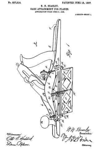
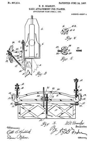
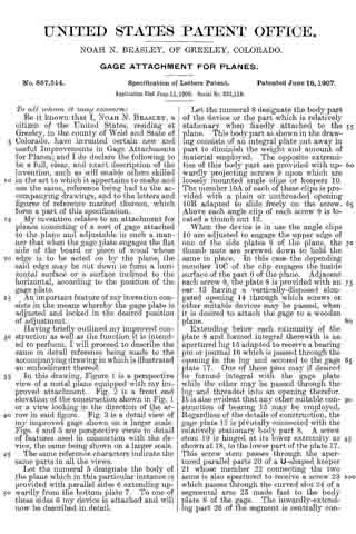
In this drawing, Figure 1 is a perspective view of a metal plane equipped with my improved attachment. Fig. 2 is a front end elevation of the construction shown in Fig. 1 or a view looking in the direction of the arrow in said figure. Fig. 3 is a detail view of my improved gage shown on a larger scale. Figs. 4 and 5 are perspective views in detail of features used in connection with the device, the same being shown on a larger scale.

The same reference characters indicate the same parts in all the views.

Let the numeral 5 designate the body of the plane which in this particular instance is provided with parallel sides 6 extending upwardly from the bottom plate 7. To one of these sides 6 my device is attached and will now be described in detail.

Let the numeral 8 designate the body part of the device or the part which is relatively stationary when fixedly attached to the plane. This body part as shown in the drawing consists of an integral plate cut away in part to diminish the weight and amount of material employed. The opposite extremities of this body part are provided with upwardly projecting screws 9 upon which are loosely mounted angle clips or keepers 10. The member 10A of each of these clips is provided with a plain or unthreaded opening 10B adapted to slide freely on the screw. Above each angle clip of each screw 9 is located a thumb nut 12.

When the device is in use the angle clips 10 are adjusted to engage the upper edge of one of the side plates 6 of the plane, the thumb nuts are screwed down to hold the same in place. In this case the depending member 10C of the clip engages the inside surface of the plart 6 of the plane. Adjacent each screw 9, the plate 8 is provided with an ear 13 having a vertically-disposed elongated opening 14 through which screws or other suitable devices may be passed, when it is desired to attach the gage to a wooden plane.

Extending below each extremity of the plate 8 and formed integral therewith is an apertured lug 15 adapted to receive a bearing pin or journal 16 which is passed through the opening in the lug and secured to the gage plate 17 . One of these pins may if desired be formed integral with the gage plate while the other may be passed through the lug and threaded into an opening therefor. It is also evident that any other suitable construction of bearing 15 may be employed. Regardless of the details of construction, the gage plate 17 is pivotally connected with the relatively stationary body part 8. A screw stem 19 is hinged at its lower extremity as shown at 18, to the lower part of the plate 17. This screw stem passes through the apertured parallel parts 20 of a U-shaped keeper 21 whose member 22 connecting the two arms is also apertured to receive a screw 23 which passes through the curved slot 24 of a segmental arm 25 made fast to the body plate 8 of the gage. The inwardly-extending part 26 of the segment is centrally connected with the plate 8 and between this connection and the slotted part is formed an offset 27 to make room for the keeper 21 and the screw stem 19 whereby the screw stem may occupy a central position with reference to the parts 8 and 17 ofthe gage. On the opposite side of the slotted segment from the keeper, a thumb nut 28 is applied to the screw 23.

The shank of the screw adjacent the head or where it passes through the keeper, should be formed square or angular in cross section to fit a counterpart opening in the keeper, to prevent the screw from turning while tightening the thumb nut.

Mounted on the screw stem 19 and occupying a position between the arms 20 of the keeper, is a thumb nut 29 which is employed to adjust the position of the gage plate, whereby the latter may be thrown to any desired angle to the plane of the body part 8.

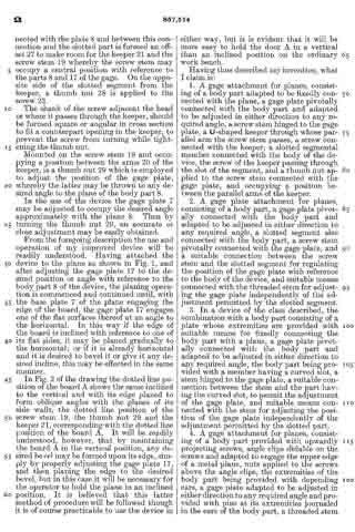
ln the use of the device the gage plate 7 may be adjusted to occupy the desired angle approximately with the plane 8. Then by turning the thumb nut 29, an accurate or close adjustment may be easily obtained.

From the foregoing description the use and operation of my improved device will be readily understood. Having attached the device to the plane as shown in Fig. 1, and after adjusting the gage plate 17 to the desired position or angle with reference to the body part 8 of the device, the planing operation is commenced and continued until, with the base plate 7 of the plane engaging the edge of the board, the gage plate 17 engages one of the flat surfaces thereof at an angle to the horizontal. In this way if the edge of the board is inclined with reference to one of its flat sides, it may be planed gradually to the horizontal; or if it is already horizontal and it is desired to bevel it or give it any desired incline, this may be effected in the same manner.

In Fig. 2 of the drawing the dotted line position of the board A shows the same inclined to the vertical and with its edge planed to form oblique angles with the planes of its side walls, the dotted line position of the screw stem 19, the thumb nut 29 and the keeper 21, corresponding with the dotted line position of the board A. It will be readily understood, however, that by maintaining the board A in the vertical position, any desired bevel may be formed upon its edge, simply by properly adjusting the gage plate 17, and then planing the edge to the desired bevel, but in this case it will be necessary for the operator to hold the plane in an inclined position. It is believed that this latter method of procedure will be followed though it is of course practicable to use the device in either way , but it is evident that it will be more easy to hold the door A in a vertical than an inclined position on the ordinary work bench.

Having thus described my invention, what I claim is:

1. A gage attachment for planes, consisting of a body art adapted to be fixedly connected with the plane, a gage plate pivotally connected with the body part and adapted to be adjusted in either direction to any required angle, a screw stem hinged to the gage plate, a U-shaped keeper through whose parallel arm the screw stem passes, a screw connected with the keeper, a slotted segmental member connected with the body of the device, the screw of the keeper passing through the slot of the segment, and a thumb nut applied to the screw stem connected with the gage plate, and occupying a position between the parallel arms of the keeper.

2. A gage plate attachment for planes, consisting of a body art, a gage plate pivotally connected witii the body part and adapted to be adjusted in either direction to any required angle, a slotted segment also connected with the body art, a screw stem pivotally connected with iihe gage plate, and a suitable connection between the screw stem and the slotted segment for regulating the position of the gage plate with reference to the body of the device, and suitable means connected with the threaded stem for adjusting the gage plate independently of the adjustment permitted by the slotted segment.

3. In a device of the class described, the combination with a body part consisting of a plate whose extremities are provided with suitable means for fixedly connecting the body part with a plane, a gage plate pivotally connected with the body part and adapted to be adjusted in either direction to any required angle, the body part being provided with a member having a curved slot, a stem hinged to the gage plate, a suitable connection between the stem and the part having the curved slot, to permit the adjustment of the gage plate, and suitable means connected with the stem for adjusting the position of the gage plate independently of the adjustment permitted by the slotted part.

4. A gage attachment for planes, consisting of a body part provided with upwardly projecting screws, angle clips slidable on the screws and adapted to engage the upper edge of a metal plane, nuts applied to the screws above the angle clips, the extremities of the body part being provided with depending ears, a gage plate adapted to be adjusted in either direction to any required angle and provided with pins at its extremities journaled in the ears of the body part, a threaded stem hinged to the body part, a U-shaped keeper whose parallel arms are provided with unthreaded openings through which the threaded stem asses, a nut engaging the threaded stem and occupying a position between the said keeper arms, a screw connected with the keeper, a slotted segment through which the keeper screw passes, and a thumb nut applied to the keeper screw for locking the keeper in any desired position on the segment.

In testimony whereof I affix my signature in presence of two witnesses.

NOAH. N. BEASLEY.

Witnesses:
G. E. M. HOUSTON,
J. H. GAMBREL.

No. 295,916 – Variable Bench-Plane (Amos Fales) (1884)

[paiddownloads id=”361″]295916


UNITED STATES PATENT OFFICE.

_________________

AMOS FALES, OF DENVER, COLORADO.

VARIABLE BENCH-PLANE.

_________________

SPECIFICATION forming part of Letters Patent No. 295,916, dated April 1, 1884.
Application filed March 31, 1883. (Model.)

_________________

To all whom it may concern:

Be it known that I, AMOS FALES, of Denver, in the county of Arapahoe and State of Colorado, have invented certain Improvements in Variable Bench-Planes; and I do hereby declare that the following is a full and exact description thereof, reference being had to the accompanying drawings, making part of this specification.

These improvements are upon variable bench-planes constructed upon the general plan set forth in Letters Patent granted to me March 7, 1882, No. 254,542, and are mainly additional thereto, although I have in one or two respects changed and improved the construction therein shown and described. Except as to these changes, as hereinafter specified, I use the invention substantially as described in the said Letters Patent; but it is to be understood that the improvements herein described and claimed may be applicable to other constructions of bench-planes besides those therein set forth; and my invention is intended to embrace all applications to which the several features, any or all, may be adapted.

In the accompanying drawings, Figure 1 represents a front side view of the main stock of the bench-plane and parts belonging thereto, constructed with my present improvements, Fig. 2, a front side view of the auxiliary stock and attached parts constructed with my present improvements 5 Fig. 3, a back side view of the said auxiliary stock; Fig. 4, a top view of the two stocks connected together for use; Fig. 5, a front view of the stocks arranged as in Fig. 4; Fig. 6, a front view of the two stocks arranged for tonguing; Fig. 7, a front view of the stocks arranged for grooving; Fig. 8, a similar view of the stocks arranged to constitute a front fillister; Fig. 9, a similar view of the stocks arranged for a back fillister; Figs. 10, 11, and 12, views showing the construction of the auxiliary stock adapted to other kinds of work.

Like letters designate corresponding parts in all the figures.

First, in the construction of the main stock A, I employ an improved handle, as represented in Figs. 1 and 4. The handle proper, B, is turned in simple cylindrical form, with one side slightly flattened to rest upon a straight plane-surfaced flange, a, cast upon the stock. Screws b b attach the handle to the flange, which is suitably inclined to give the handle the proper position for grasping. Not only is this construction of the handle very simple and cheap, but it is very easy for the hand and convenient for use in connection with other parts of the instrument, not interfering with the adjustment of the cutters; also, the molds or form-plates C D, instead of having shoulders to fit under the lower edge of the stock-flange c, for holding them in proper position, I now form their vertical attaching-flanges d d each with upward extensions e e, to bear against the shoulder formed by the projecting lower edge of the body f of the stock. This construction of the form-plates leaves the lower edge of the stock-flange c free and unobstructed and enables me to permanently attach thereto one dado-spur, g, as shown in Figs. 4 to 9 of the drawings, and saves the expense of two spurs on each dado. and it is always in position for use.

Another change in the construction of the main stock consists in terminating the lower part of the cutter-bracket E at the line of the shoulder or lower edge of the body f of the stock, thereby leaving the stock without side projections beyond the stock-flange below the said line, so that very narrow grooves may be out to the full depth of the said flange.

Second, in the construction of the auxiliary stock G, I form the stock and cutter-holder in one instead of two parts or sections, thus simplifying and cheapening the construction and rendering the use ofthe stock more convenient, and enabling me to apply any other attachment which may be desired. The stock thus approximates in construction and use to the main stock.

Further, for many purposes the fiange h of the auxiliary stock extends lower than or entirely below the corresponding flange, c, of the main stock, as shown in Fig. 5 and following figures of the drawings. This enables me to use, if desired, a cutter in the main stock, which may extend laterally over the auxiliary stock, as shown, for instance, in Fig. 5. Besides, it enables me to employ, in connection with the auxiliary stock, a “fence” or gage and guide-strip, H, for uses such as illustrated in Figs. 7, 8, and 9, and hereinafter set forth. This fence is preferably made of wood, and is consequently cheap and light. It is made of the form shown or any other most convenient. It is attached to the flange h of the auxiliary stock below the body thereof, which forms a guide-shoulder, by two screws, i i passing through notches j j of the stock-flange, so that it is easily attached and detached. Its surface, which faces the main stock, is plane and parallel therewith. By adjusting the auxiliary stock to the required distance from the main stock on the connecting-bars I J this fence may be brought to bear against and run along one side of the stuff to be worked, and serve as a guide for the instrument and gage for the work.

In Figs. 4 and 5 and the following figures of the drawings I illustrate the operation of the instrument provided with the above-de-
scribed improvements.

In Figs. 4 and 5 is shown an arrangement for a front fillister, with a wide cutter, k, in the main stock overlapping the auxiliary stock, which in this case needs no cutter, but is low enough in the middle to allow the lapping over of the main-stock cutter. The flange h furnishes the side gage, and the vertical gage-stop L is mounted on the connecting-bar I, back of the main stock, to gage the depth of the cut in the board or stuff x, indicated by dotted lines in Fig. 5.

In Fig. 6 is shown an arrangement for tonguing. Here also the flange h of the auxiliary stock serves as the side gage, and the vertical gage-stop is mounted between the two stocks. The cutter k of the main stock cuts behind the tongue of the board x, and a cutter, M, in the auxiliary stock cuts in front of the tongue.

In Fig. 7 I show an arrangement for grooving. In this arrangement a fence, H, is used on the auxiliary stock for the side gage, and the vertical gage-stop I is arranged back of the main stock, the cutter k of the main stock cutting the grooves in the board or plank x, in connection with the fixed dado-spur g on the main-stock flange.

In Fig. 8 is shown an arrangement for a front fillister, with the use of a fence, H, on the auxiliary stock. By this arrangement as narrow a rabbet or shoulder may be cut in the stuff as ever will be required.

In Fig. 9 is shown an arrangernent for a back fillister, a fence, H, on the auxiliary stock furnishing the side gage, and the vertical gage-stop L being mounted between the two stocks.

Figs. 10, 11, and 12 show a construction of the auxiliary stock adapted to kinds of work in which it is not convenient for the flange h to project lower than the main stock — as, for instance, in making window-sashes. Here the stock-flange h projects horizontally, and the fence H is attached below it, the attaching-screws i i going down through notches j j, which allow a lateral adjustment of the fence.

As seen in Fig. 12, the screws i i enter the fence nearer one edge than the other. When the fence is attached, as shown, the fence is back of the front side of the stock, allowing the cutter M of the stock to cut over the sash x or other article. By reversing the position of the fence, however, the edge of the same projects in front of the stock, as required for some kinds of work. There is a notch or depression, l, Figs. 10 and 11, in the middle of the auxiliary stock, to allow the center of the main stock to reach over the auxiliary stock, when desired. The auxiliary stock is depressed under this notch, the fence being cut away to allow the two to come together.

I claim as my invention —

1. In a bench-plane, a handle, B, made of cylindrical form, flattened on one side, in combination with an inclined plane-faced flange, a, on the plane-stock. substantially as and for the purpose herein specified.

2. The combination of the main stock A, having the lower edge of its body f and cutter-bracket E in one straight line, and its flange c provided with a dado-spur, g, and the form-plates C D, having vertical attaching-flanges d d bearing against the straight lower edge of the said stock-body and bracket, and adapted to have their lower surfaces flush with the lower edge of the said stock-flange, substantially as and for the purpose herein specified.

3. The reversible fence H, in combination with the stock G, the points of attachment being to one side of the middle longitudinal line of the fence, whereby two positions are given thereto fulfilling two purposes, substantially as herein specified.

4. The combination of the main stock A, having a downwardly-extended flange, c, on its lower edge, and a cutter extending laterally beyond the stock, and the auxiliary stock G, cut away at the top to allow the main-stock cutter to project over it, and having a flange, h, bent laterally, substantially as and for the purpose herein specified.

In testimony whereof I have signed my name in presence of two witnesses.

AMOS FALES.

Witnesses:
J. DEWEESE,
H. T. CASTLE.

No. 289,459 – Spokeshave (Gary B. Smith) (1883)

[paiddownloads id=”349″]289459


UNITED STATES PATENT OFFICE.

_________________

GARY B. SMITH, OF DENVER, COLORADO, ASSIGNOR TO ROBERT E. PERRY, OF SAME PLACE.

SPOKESHAVE.

_________________

SPECIFICATION forming part of Letters Patent No. 289,459, dated December 4, 1883.
Application filed August 15, 18803. (No model.)

_________________

To all whom it may concern:

Be it known that I, GARY B. SMITH, a citizen of the United States of America, residing at Denver, in the State of Colorado, have invented certain new and useful Improvements in Spokeshaves; and I do hereby declare the following to be a full, clear, and exact description of the invention, such as will enable others skilled in the art to which it appertains to make and use the same.

This invention relates to that class of spoke-shaves having adjustable bevel gage-stops, which serve to gage the spokeshave for chamfering; and the objects of this improvement are to fit the parts composing the bevel gage-stop without the aid of screws and to improve the construction of this class of spokeshaves, whereby the material (wood) can be accurately cut at all the desired angles.

With these and other objects in view my invention consists in a bevel gage-stop for a spokeshave, composed, essentially, of three parts united for angular inclinations. My invention further consists in the novel construction and combination of parts, as will be hereinafter more fully set forth.

In the annexed drawings, Figure 1 is a side view, partially in section, of my improved spokeshave. Fig. 2 is a plan view of the under side of the stock. Fig. 3 is a perspective view of the bevel gage-stop. Fig. 4 is a plan view of the angle-plate. Fig. 5 is a perspective view of the horizontal plate, and Fig. 6 is a plan view of the bar that connects the angle and horizontal plates.

In the manufacture of the spokeshave the stock A is preferably made of malleable iron, and is formed with two parallel grooves, b, extending in the direction of the length of the stock. The continuity of one of these grooves is broken about midway of its length by the throat-slot c, for the reception and passage of the plane-bit d and set-iron with its screw, as seen in Figs. 1 and 2 of the drawings. This stock is also formed at the opposite ends with the longitudinal slots e e, for the reception. and adjustment of the thumb-screws f, connected to the bevel gage-stops, hereinafter described; also, the continuation of the slots into and the enlargement of the same in the ends of the stock will permit of the ready removal of the stops. This is accomplished by loosening the set-screws f a little, then adjusting the stops until the set-screws drop through the enlarged openings. The bevel gage-stop B, as seen in Figs. 1 and 3, is essentially composed of the horizontal plate C, the angular face-plate D, and the diagonal connecting-bar E. The horizontal plate B is formed with two longitudinal tongues, h, arranged to fit and work in the grooves b of the stock. Its inner end is formed with an overlap-joint, i, for attachment to the transverse bar K of the angular face-plate D, and the plate is also formed with a longitudinal slot, in, for the reception of a rectangular or other shaped boss, n, on the upper end of the connecting-bar E. The opposite or lower end of the angular face-plate D is formed with a concave or depression, r, and a slot, s, in the concave part to receive the reduced portion and cross-bart of the connecting-bar, as shown in Figs. 1 and 2 of the drawings. The connecting-bar, in connection with the slot in the horizontal plate and thumb-screw, is for adjusting the inclination of the angular face-plate. By this construction of the members composing the bevel gagestop the parts are readily coupled together without the aid of auxiliary fastening means, and no portion of the connecting means projects beyond the face of the angular plate. The bevel gage-stops are attached to opposite sides of the plane-bit, as seen in Fig. 1 of the drawings, by means of the thumb-screws passed through the slots of the stock and connected to the rear ends of the connecting-bars of the gage-stops. To adjust the gage-stops to or from the plane-bit, or to secure a different angle to the face-plates D, the thumb-screws are loosened and the gage-stops are adjusted as desired, or the inclination of the face-plates set at the required angle, when the thumb-screws are again made secure.

This spokeshave is used substantially in the manner as those of the same class. I wish to reserve the right to vary the construc-
tion and arrangement of parts without departing from the spirt of the invention.

What I claim is —

1. In a spokeshave, the bevel gage-stop composed, essentially, of the slotted horizontal plate, the angular face-plate hinged to the inner end of the horizontal plate, and the adjustable connecting-bar loosely connected to the lower end of the faceplate with a set-screw, substantially as set forth.

2. In a spokeshave, the combination of the horizontal-plate formed at one end with an overlap joint, and the angular face-plate formed with the transverse bar for connection with the overlap-joint of the horizontal plate, whereby a hinge-connection is formed for the relative adjustment of the face-plate, substantially as described.

3. The bevel gage stop for a spokeshave, consisting of the slotted horizontal plate formed with the parallel ribs and overlap-joint, the angular face-plate formed with the transverse bar and the concave or depression, and the connecting-bar formed with the boss and the cross-bar, said members being organized substantially as described.

4. The improved spokeshave consisting, essentially, of the stock; formed with longitndinal slots enlarged at the outer ends, slotted plates with the angular face-plates and connecting-arms, said plates and arms being connected as described, and the thumb-screws, substantially as and for the purposes set forth.

In testimony whereof I affix my signature in presence of two witnesses.

G. B. SMITH.

Witnesses:
JOHN W. WEBSTER,
AUBREY PERRY.

No. 254,542 – Variable Bench-Plane (Amos Fales) (1882)

[paiddownloads id=”318″]254542


UNITED STATES PATENT OFFICE.

_________________

AMOS FALES, OF DENVER, COLORADO.

VARIABLE BENCH-PLANE.

_________________

SPECIFICATION forming part of Letters Patent No. 254,542, dated March 7, 1882.
Application filed December 12, 1881. (No model.)

_________________

To all whom it may concern:

Be it known that I, AMOS FALES, of Denver, in the county of Arapahoe and State of Colorado, have invented an Improved Kit-Plane, or combination instrument for planing, tonguing and grooving, rabbeting, plowing, and forming beads and moldings of various forms and styles; and I do hereby declare that the following is a full and exact description thereof, reference being had to the accompanying drawings, making part of this specification —

Figure 1 being a view of the near or working side of the kit-plane; Fig. 2, a view of the opposite side of the same; Fig. 3, a top view thereof; Fig. 4, a cross-section thereof in a plane indicated by the line x x, Fig. 1; Fig. 5, a cross-section in a plane indicated by the line y y, Fig. 1; Figs. 6, 7, 8, and 9, cross-sections of the stock, showing in place different forms of face-plates or molds attached to the stock; Fig. 10, a view of one of the bits or cutters used with the molds, representing two forms; Fig. 11, a view in perspective, showing an auxiliary stock or attachment, connected with the main stock by gage-bars, for various purposes; Figs. 12 and 13, respectively, opposite side views of the attachment or auxiliary stock; Figs. 14: and 15, partial sections, showing parts in detail.

Like letters designate corresponding parts in all of the figures.

My invention consists in a kit plane of simple but peculiar construction, by which are combined a stock adapted to receive any required kind of bit or cutter for producing various shapes of moldings and other outlines in wood-work, and attachable and detachable forms or molds of various shapes, to correspond with those of the cutters, for performing a great variety of work which ordinarily require many different planes or instruments.

The plane-stock A is of very simple and light construction. It may be made of metal — say of cast-iron — finished suitably, and accurate in shape, and it may have a wooden handle, B, attached to the stock by screws a a. This of course is at the rear end of the stock, and it has or may preferably have a wooden knob, C, near the front end, on top, for holding and guiding the instrument with the left hand.

On the working side of the stock, near the middle thereof, an oblique projecting ledge or bracket, D, is cast on or attached to the stock, on which ledge the various cutters used with the instrument rest when employed. Each cutter E is supported by this ledge, guided only at one edge, next to the stock, the opposite edge being free, so that various widths of cutters may be used with the stock.

Instead of a wedge working downward to fasten each cutter in the stock, I employ a wedge, G, working horizontally and entering a deep wedge-shaped notch or recess, b, in the stock, which is enlarged on the opposite side, as shown in Fig. 3, to compensate for the weakening produced by the said notch, and thereby to give uniform strength throughout the length of the stock. A horizontal screw-bolt, c, passes through the wedge G, or is otherwise made fast to it, and thence extends through and projects a little beyond the stock, on the opposite side thereof. On this screw-threaded end of the bolt a hand-nut, d, screws against the side of the stock, and thereby draws the wedge into its notch or socket, and tightens and holds the cutter fast on its ledge. Thus not only is each cutter always securely held and easily adjusted, but great facility is afforded for changing cutters.

The upper part, e, of the stock is made thick enough to give necessary strength and to suitably attach other parts directly connected therewith. The lower part, f is a thin blade or flange to which to attach the planing-molds, now to be described.

In connection with the various forms of cutters to be used in the stock, two face-plates or molds, H I, are used, one situated forward of and the other back of the cutter, substantially as shown in Fig. 1. Each pair of molds for each different form of cutter is of like form in cross-section to fit the form produced by the cutter between them and guide the plane and hold it in the proper course. Each one has a vertical flange, g, fitting against one side of the flange f of the plane-stock, and by this flange it is united to the stock with a screw, h, passing through both flanges, and a hand-nut, i, turning thereon, one screw and nut serving for each mold. For convenience in attaching and detaching the molds, the opening in the flange g to receive the screw is a notch, as shown in Fig. 1, so that the attachment and detachment can be effected without removing the nut simply by loosening and then retightening the same. To hold the molds thus attached in accurate position, there is a shoulder, j, from each under the lower edge of the stock-flange f as shown in the several cross-sections. The body or form it of each mold projects laterally from the flange in a general horizontal direction, but varied according to its form, as seen also in the several cross-sections showing different forms of molds.

Several of the more common forms of molds which may be used with this kit- plane are shown in the drawings. Thus Fig. 4 has the dado form or mold; Fig. 5, a fillister form, with adjustable gage l thereon; Fig. 6, a hollow form, for producing a convex molding; Fig. 7, a round or convex form, for producing a concave molding; Fig. 8, a bead-mold, and Fig. 9 a “snipe’s-bill” mold. All these and other molds to be used have corresponding forms of cutters at the cutting-edge thereof. Thus Fig. 10 shows a cutter having a form or cutting-edge at each end, that at one end corresponding and used with the hollow mold shown in Fig. 6, while that at the other end has a form corresponding and used with the convex mold shown in Fig. 7.

Ordinarily thus two forms of cutter may be united in one, if economy of expense and room occupied by the whole instrument is desired. These molds or face-plates may be made thin and light, since very little strain comes upon them, and they are very well and securely held on the stock. They are so simple in construction and easy of application that when any one wants any particular style of molding, bead, or other work for which he has no mold or cutter he can easily shape molds — say out of wood — a little thicker than the metallic forms, as shown, and make a cutter to correspond. In this manner, at little expense, one can supply himself with almost anything of the kind which he may desire.

Some of the cutters and molds used with this instrument require a gage-stop to limit the depth to which they shall go. Thus for the dado and fillister shown in Figs. 4 and 5 such a stop needs to be used, and I have shown in Fig. 5, as well as in Fig. 1, my construction and arrangement for this purpose. I employ a transverse bar, J, which extends through a mortise or notch, m, in the stock, and this, for convenience, is held in position by the knob C, which, screwing down on the stock, serves as a nut to hold the bar, which can thereby be adjusted longitudinally to any desired position. This bar carries the gage-stop K, the stem n of which passes up through a hole in the bar, and is held at any height to which it may be adjusted by a set-screw, o.

For some special purposes, where two cutters are required running parallel with each other, I employ a light auxiliary stock, L, as shown in Figs. 11, 12, and 13, the former figure showing the stock and the means of connecting it with the main stock, and the latter two figures showing opposite side views of the cutter-holder separate. This stock is of similar construction to the main stock, but it is not so heavy, and does not require a handle nor a holding-knob. It has a similar construction for holding and securing its cutters and similar molds, corresponding in form with the respective cutters; but the cutters and molds are placed on the other side of the stock, as compared with the main stock, so that the two stocks and their adjuncts are right and left to one another, the cutters and molds of both being inward and facing one another, as shown.

The two stocks are connected together by two bars, J M, the former fitting the mortise m in the main stock and taking the place of the gage-bar J, above described, being held in the main stock by the knob C; but it may be required to be longer than the said gage-bar for its purposes. It extends through a corresponding mortise or aperture in the auxiliary stock, and is held fast therein by a set-screw, p. The other bar, M, parallel with the former bar, passes through holes or mortises in the two stocks, and is held therein by set-screws q, that in the main stock not being represented in the drawings. The bar M may be round. By this construction the auxiliary stock may be adjusted to any desired distance from the main stock.

On the bar J a gage-stop, K, is used, similar to that on the bar J; but it is represented in Fig. 11 as constructed to slide on the bar. Its construction is shown in Fig. 14. It is secured in any position by a set-screw, o.

With a proper cutter in the holder O, together with a suitable cutter in the main stock, the two sides of a tongue for tonguing and grooving are formed. By adjusting the auxiliary stock farther from or nearer to the main stock a thicker or thinner tongue is made.

By making the cutter-holder O detachable from the auxiliary stock and attaching a dado or fillister form, P, (shown separate in Fig. 15,) to the back part of the auxiliary stock, a back fillister is produced to go with the main instrument. The cutter-holder O and fillister form P are attached to the auxiliary stock by bolts and thumb-screws s s, Fig. 11.

The above are instances which indicate also other and varied uses of which the entire instrument is capable.

This whole instrument, with all the parts herein described, by taking apart, can be packed in a box less than a foot in length, six inches in breadth, and four inches in depth, interior dimensions, and thus a complete set of such instruments becomes very portable and compact and of comparatively small cost. Instruments of the ordinary construction having all the various capabilities and uses herein specified, if made separately, would occupy many times as much space and be many times more expensive.

What I claim as my invention, and desire to secure by Letters Patent, is —

1. A kit-plane constructed with a stock, A, as described, changeable cutter E, and separate changeable front and back form-plates, H I, the said form-plates being independently attached to the stock, substantially as and for the purpose herein specified.

2. The stock A, constructed with a ledge or bracket, D, projecting from one side thereof, and of sufficient width to support all the different widths of cutters used, with the laterally-acting wedge G to clamp the cutters on the ledge, and with the vertical flange f, to one side of which the front and back form-plates are attached, substantially as and for the purpose herein specified.

3. The separate form-plates or molds H I, each constructed with the horizontally-extended body or form k, the vertical flange g, for attaching to the stock-flange f and the ledge or shoulder j, for holding them accurately in line under the flange f, substantially as and for the purpose herein specified.

4. The combination, with the stock A, of the cross-bar J and gage-stop K, the former being horizontally adjustable in the stock and the latter mounted and vertically adjustable in the cross-bar, substantially as and for the purpose herein specified.

5. The auxiliary stock L and its removable cutter-holder O and mold-forms P, in combination with the main instrument, substantially as and for the purpose herein specified.

The foregoing specification signed by me this 22d day of August, 1881.

AMOS FALES.

Witnesses:
A. C. LEWIS,
J. P. LESHEN.