No. 195,480 – Improvement In Circular Planes (Henry M. Clark) (1877)

[paiddownloads id=”282″]195480


UNITED STATES PATENT OFFICE.

_________________

HENRY M. CLARK, OF NEW BRITAIN, CONNECTICUT, ASSIGNOR TO THE STANLEY RULE AND LEVEL COMPANY, OF SAME PLACE.

IMPROVEMENT IN CIRCULAR PLANES.

_________________

Specification forming part of Letters Patent No. 195,480, dated September 25, 1877 application filed August 6, 1877.

_________________

To all whom it may concern:

Be it known that I, HENRY M. CLARK, of New Britain, in the county of Hartford and State of Connecticut, have invented certain new and useful Improvements in Circular Planes, of which the following is a specification:

My invention consists of a connecting mechanism for the two ends of the flexible bottom of a circular plane, so that they necessarily move together, in combining therewith a single operating device, in the peculiar construction of parts, and in their combination, as hereinafter described.

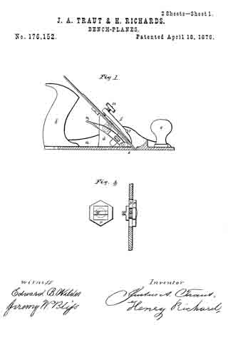
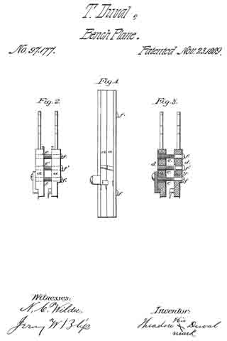
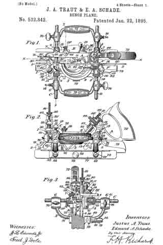
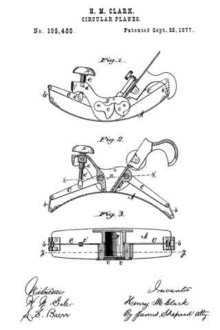
In the accompanying drawings, Figure 1 is a side elevation of a circular plane, which embodies my invention. Fig. 2 is a vertical section of the same on line y y of Fig. 3, and Fig. 3 is a horizontal section of the same on line x x of Fig. 2.

In Fig. 1 the flexible bottom A is set in a convex position for dressing a concave surface, and in Figs. 2 and 3 it is set in a concave position for dressing a convex surface.

Circular planes having a flexible bottom and mechanism for holding the same when set in various circles are old; but, so far as I know, the two ends of the flexible bottom have never before been so connected as to necessitate their simultaneous movement. These prior planes had no mechanism for moving the ends of the flexible bottom, but only mechanism for holding the ends in place when moved by hand; and these holding mechanisms were entirely independent of each other, so that unless great care was taken in setting the bottom, one end would be bent to conform to one sized circle and the other end to conform to a circle of a different size.

The object of my invention is to adjust the flexible bottom more conveniently than heretofore, and to always adjust both ends to the same circle.

The flexible bottom A is secured to the stock B by screws taking into the stock at each side of the throat, in the usual manner of securing the same in circular planes.

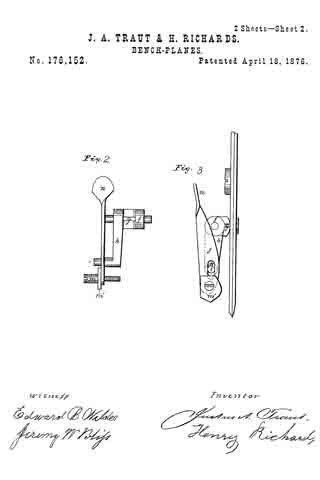
At one side of the stock B short shafts a a are secured in proper bearings, so as to partially rotate therein. On the inner ends of said shafts a a, and in the middle of the stock B, rocking levers C C are rigidly secured, so as to rotate with said shafts. The outer ends of the rocking levers C C are connected to the ends of the flexible bottom A by means of the links b b.

On the outer ends of the shafts a a, rigidly secured, are segment-gears c c, which mesh into each other and necessitate the movement of one shaft with its fellow.

Inasmuch as the rear end of the flexible bottom is longer than its front end, and describes a larger circle in bending, the segment-gear on the front or short end is made larger than the segment-gear on the long end, in order to cause the latter to move enough faster than the former to compensate for the difference in the size of the circle described by the two ends of the flexible bottom.

In the front end of the stock B there is a rocking block or nut, d, which receives the adjusting-screw e, surmounted by a suitable knob or handle, D. The screw e is also provided with an internal thread, running in the opposite direction from that of its external thread, which internal thread receives the adjusting-screw e’, the lower end of which is connected by a pin or other jointed connection to one of the levers.

By turning the adjusting-screw e e’, the lever C, to which it is connected, is either depressed or lowered, according to which way the screw is turned, thereby partially rotating the shaft a. The segment-gear on the outer end of the shaft, meshing into a like gear on its fellow shaft, carries the opposite lever with the one connected to the screw, and the ends of the flexible bottom being connected by the links to said levers, as shown, must necessarily move together; and if the size of the segment-gears is properly arranged in relation to the circles described by both ends of the flexible bottom, said ends will both of them always be bent to conform to the same circle under all the various adjustments which they undergo.

The double screw e e’ is merely for the purpose of increasing the motion of the lever, and may, if desired, be omitted, and a single screw substituted therefor.

Other means might be employed for moving the levers or securing them in place without changing the portion of the invention which relates to moving both ends of the flexible bottom together.

If desired, the segment-gears might be separated a little and a worm placed between them, so as to engage the teeth thereof, whereby turning the worm will simultaneously move both segment-gears, levers, &c., in either of which modifications a single handle only has to be manipulated to operate both ends of the flexible bottom.

I claim —

1. In a circular plane, the combination of the flexible bottom A and mechanism, substantially as described, connecting its two ends, for necessitating their simultaneous movement, substantially as described.

2. In a circular plane, the combination of the flexible bottom A, mechanism, substantially as described, connecting its two ends and necessitating their simultaneous movement, and a single adjusting or operating handle, substantially as described, and for the purpose specfiied.

3. In a circular plane, the combination of the stock B, flexible bottom A, link b, rocking lever C, and adjusting-screw e, substantially as described, and for the purpose specified.

4. In a circular plane, the combination of the flexible bottom A, links b b, levers C C, shafts a a, and sement-gears c c, substantiallly as described, and for the purpose specified.

HENRY M. CLARK.

Witnesses:
T. A. CONKLIN,
JAMES SHEPARD.

No. 192,132 – Improvement In Bench-Planes (Samuel D. Sargent) (1877)

[paiddownloads id=”279″]192132


UNITED STATES PATENT OFFICE.

_________________

SAMUEL D. SARGENT, OF NEW BRITAIN, CONNECTICUT, ASSIGNOR TO THE STANLEY RULE AND LEVEL COMPANY, OF SAME PLACE.

IMPROVEMENT IN BENCH-PLANES.

_________________

Specification forming part of Letters Patent No. 192,132, dated June 19, 1877; application filed November 4, 1876.

_________________

To all whom it may concern:

Be it known that I, SAMUEL D. SARGENT, of New Britain, in the county of Hartford and State of Connecticut, have invented certain new and useful Improvements in Bench-Planes, of which the following is a specification:

My invention consists, in a device for adjusting plane-bits, of a link constructed to operate in the manner hereinafter shown and described.

In the accompanying drawing, Figure 1 is a longitudinal section of a bench-plane which embodies my invention. Fig. 2 is a plan view of the same with the cap and plane-irons removed. Figs. 3 and 4 are side elevations, showing diifcrent modifications of the adjusting mechanism for said plane; and Fig. 5 is a diagram to aid in the explanation of my invention.

A designates the stock, and B the handle, both of which may be of any ordinary form and of any suitable material.

The object of my invention is to provide cheap, simple, and eflicient means for adjusting the cutting-bit in its proper position within the stock.
C designates the bit, which may be either a single or double iron, as may be desired. Upon the under side of said bit a series of alternate ribs and channels are formed, as shown in Fig. 1. Upon the under side of the frog a, which frog is the bed upon which the plane iron or bit rests, there is a screw, b, which, in Fig. 1, is a fixed stud threaded externally, and upon it is a larger screw, c, threaded internally to fit the screw b, and externally to fit the nut d, which it carries, the external. thread of the screw c being one banded, and its internal thread and thread of the screw b being threaded in the reverse direction. The larger screw c is also provided with a suitable head, D, or operating-handle.

To the nut d of the screw c one end of a link, e, is secured, and its opposite end lies loosely in a longitudinal slot formed in the frog a, as shown in Fig. 2. This lower end of the link e has a thin projection, which projects a little above the face of the frog, and engages in one of the grooves or channels formed in the under side of the bit, and it is necessary that the link at this end shall rest on ways or other support, so that said end cannot disengage from the plane-bit. The link between its two ends must be clear of all bearings, so as to allow of its free movement. The ordinary holding-cap E, or other proper means, holds the bit in place.

By turning the screw c in one direction the nut d is forced toward the frog a, carrying with it that end of the link e, and, as said link cannot change its length, it follows that the lower end, which is engaged with the cutting-bit, must move downward in the slot in the frog a, and, being so engaged. it must also force the cutting-bit downward with it. By turning the screw in the opposite direction the bit is drawn upward.

The link, for convenience’ sake, is made crooked; but its operation is the same, so long as it is sufficiently rigid, as if it was formed on a straight line between its ends — that is, from the point at which it is secured to the nut to its projecting point at the time of the frog. The operation of this link is, perhaps, more clearly illustrated by reference to the diagram, Fig. 5. The screw, the frog, and the link together form a triangle. In Fig. 5 the side J K is the base of the triangle, and represents the axial line of the screw; the side J 1 the perpendicular, and represents the face line of
the frog, and the side K 1 the hypotenuse, and represents the axial line of the link.

ln the adjustment of the plane iron with this triangular mechanism the link or hypotenuse of the triangle is made to change its position; but it is so confined that its two ends will always be one on the base-line, and the other on the perpendicular-Iine, of a triangle. Three different positions of the link are represented in Fig. 5 — the first by the solid line K 1, the second by the broken line L 2, and the third by the dotted line M 3 — by which it will be seen that, as one end of the hypotenuse is changed in such direction as to shorten the base, the vertex of the vertical angle is carried away from the base. In the diagram the vertex of the vertical angle is changed about one-eighth of an inch for every change there represented. A link engaging with a plane-bit, and changing its position in like manner, would move said bit one-eighth of an inch for every such change.

In Fig. 1 there is a compound screw, hereinbefore described. Its object is to get all the advantage of a fine-threaded screw and the speed of a coarse-threaded one. Such compound screw moves the nut fd just twice as far as it would be moved by it single screw having the same number of threads to an inch, whereby a less number of revolutions of the screw are required in order to effect the desired adjustment than with a single screw.

In Fig. 3 a single screw, F, is shown; but the link and nut are the same as those shown in Fig. 1. The screw is also set at an oblique angle to the face of the frog, in which position the movement of the nut endwise on the screw gives a greater range of motion to the lower end of the link than it would otherwise have.

In Fig. 4 two links, f g, are employed, and jointed together at their meeting ends. The link g is confined to the frog at one end to prevent longitudinal movement. An arm or extension at one end of the link f rests in at grooved nut, h, working on the screw G, and the opposite end of said link f plays loosely in a slot in the frog, as before described for the link e, the object of the additional link g in said rnodification being merely to give a little more throw to the adjustment.

In all of the modifications and mechanisms herein described the link e is employed and arranged to operate substantially the same.

I claim as my invention —

In a device for adjusting plane-bits, the link e, constructed to operate substantially as shown and described, for the purpose set forth.

SAMUEL D. SARGENT.

Witnesses:
FRED. N. STANLEY,
T. A. CONKLIN.

No. 189,415 – Improvement In Bench-Planes (Leonard Bailey) (1877)

[paiddownloads id=”276″]189415


UNITED STATES PATENT OFFICE.

_________________

LEONARD BAILEY, OF HARTFORD, CONNECTICUT.

IMPROVEMENT IN BENCH-PLANES.

_________________

Specification forming part of Letters Patent No. 189,415, dated April 10, 1877; application filed February 16, 1877.

_________________

To all whom it may concern:

Be it known that I, LEONARD BAILEY, of Hartford, in the county of Hartford and State of Connecticut, have invented certain new and useful Improvements in Bench-Planes; and I do hereby declare that the following is a full, clear, and exact description thereof, whereby a person skilled in the art can make and use the same, reference being had to the accompanying drawing, and to the letters of reference marked thereon.

Like letters in the figures indicate the same parts.

My improvement relates to such bench-planes as are provided with an adjustment for regulating the depth of cut while the bit remains set in the stock.

My invention has for its object a better means of accomplishing the adjustment of the cutting-edge of the bit or iron in the throat of the stock, so as to produce the desired result; and it consists in the mechanical combination and arrangement of the several parts, as will be hereinafter described, and as an improvement upon Letters Patent granted to me December 12, 1876, No. 185,280.

In the accompanying drawing, Figure 1 is a side view of my improved plane. Fig. 2 is a top view with the cap and bit removed, so as to show the top of the adjusting mechanism. Fig. 3 is a top view of the bit or iron removed from the stock. Fig. 4 is a view of the back or under side of the adjusting mechanism removed from the stock.

A is the stock. B is the bit or iron. C is a cap, corresponding to the wedge, for holding the bit in place. It is provided with ears which enter into slots in the stock, and its lower edge rests upon the bit. It is provided with the set-screw D, operated by the handle E, for clamping the bit firmly down upon its bed.

F is a milled head for operating the adjusting mechanism. It has the pinon G, which turns with it and gears into the wheel H. Both of these wheels turn upon axes fixed in the plate I.

The wheel H is provided with the cam-slot J, in which runs the stud K, which also passes through the plate I, which is furnished with a straight slot, and is attached to the link L. This link moves longitudinally in a groove in the upper side of the plate I, and lies immediately under and next to the bit B when it is in place. The stud M upon the lower end of the link enters into one of the holes N in the bit, and communicates motion to it from the cam-slot in the wheel H when the milled-headed wheel F is turned.

By means of my invention a regular and slow motion can be given to the bit to advance or withdraw it through the throat of the stock.

It will also be observed that on account of the multiplying wheels G and H, the cam can be made short, not to exceed a complete turn, so that it can be constructed with a variable inclination, and be of such a form that at any point an equal amount of turn in the head F will advance the bit an equal amount. This gives the user of the tool a better control over the movement of the cutting-edge, and enables him to set it exactly without waste of time.

What I claim as my invention is —

The combination of the longitudinally-slot ted bed-plate I, the link L, provided with the studs M K, the pinion G, and the gear-wheel H, having the cam-slot J, constructed to operate as shown and described, and for the purpose specified.

LEONARD BAILEY.

Witnesses:
THEO. G. ELLIS,
WILMOT HORTON.

No. 186,998 – Improvement In Bench-Planes (Henry A. Foss) (1877)

[paiddownloads id=”275″]186998


UNITED STATES PATENT OFFICE.

_________________

HENRY A. FOSS, OF NEW BRITAIN, CONNECTICUT.

IMPROVEMENT IN BENCH-PLANES.

_________________

Specification forming part of Letters Patent No. 186,998, dated February 6, 1877; application filed January 9, 1877.

_________________

To all whom it may concern:

Be it known that I, HENRY A. FOSS, of New Britain, in the county of Hartford and State of Connecticut, have invented a new Improvement in Bench-Planes; and I do hereby declare the following, when taken in connection with the accompanying drawings and the letters of reference marked thereon, to be a full, clear, and exact description of the same, and which said drawings constitute part of this specification, and represent, in —

Figure 1, a side view, and in Fig. 2 a longitudinal central section; and Fig. 3, a modiication.

This invention relates to an improvement in the method of adjusting the bit or iron of bench-planes. It consists in the arrangement of a differential screw, one portion of which is connected with the bit, the other with the stationary nut, and so that, by turning the screw, the iron will be moved only the difference between the thread of the two parts, as more fully hereinafter set forth.

A is the body of the plane; B, the handle; C, the bit or plane-iron, held in place by the clamp D, all in substantially the usual manner. Referring to Fig. 2, the screw is shown as made in two parts. In rear of the bit C, and in a line substantially parallel thereto, one part, E, of the screw is arranged, its lower end supported in a suitable socket, F, and with an arm, G, extending toward the bit, and connected therewith through the cap-screw H or otherwise, so that the movement of the screw will move the bit accordingly. Onto the part E of the screw the second tubular part L of the screw is set, threaded both inside and out, the inside thread corresponding to the thread of the part E, and either coarser or finer than the thread on the outside of the part L — that is, so that there be a substantial diierence in the two threads. The part L is placed in a stationary nut, N, and is provided with a suitable head, P, by which it may be turned. The screw-threads are both the same — that is, both right or left hand threads, as may be desirable — therefore, by turning the part L so as to run it downward, the part E will correspondingly run up into the part L, and the downward movement of the part L will be only the diderence between the two threads; as, for instance, suppose the external thread ofthe part L to be twenty, and that of the part E thirty, then a full revolution of the part L would run that screw down one-twentieth of an inch, and draw the part E up one-thirtieth of an inch; hence the downward movement of the part L would be one-sixtieth of an inch, and the bit would be moved accordingly. This enables a very iine and delicate adjustment of the bit, but yet positive and firm in its operation.

Instead of making the differential screw in two parts, as in Fig. 2, it may be a single piece, as in Fig. 3, the upper part L engaging in the nut in the same manner as the first illustration, the lower part E working in a connection which extends to the bit; making therefore the same difference between the two parts E and L, the same result will be attained.

I am aware that various devices have been used in bench-planes for the mechanical adjustment of the bit, and that among these a single screw has been used; I therefore do not wish to be understood as broadly claiming such a mechanical device; but

What I do claim as my invention, and desire to secure by Letters Patent, is —

ln combination with the body and bit of a bench-plane, a differential screw, one part working in connection with the bit, the other in a stationary nut, substantially as and for the purpose described.

HENRY A. FOSS.

Witnesses:
AUSTIN HART,
MICHAEL T. TOOMEY.

No. 186,281 – Improvement In Devices For Adjusting Plane-Irons (Justus A. Traut) (1877)

[paiddownloads id=”274″]186281


UNITED STATES PATENT OFFICE.

_________________

JUSTUS A. TRAUT, OF NEW BRITAIN, CONNECTICUT.

IMPROVEMENT IN DEVICES FOR ADJUSTING PLANE-IIRONS.

_________________

Specification forming part of Letters Patent No. 186,281, dated January 16, 1877; application filed January 24, 1876.

_________________

To all whom it may concern:

Be it known that I, JUSTUS A. TRAUT, of New Britain, in the county of Hartford and State of Connecticut, have invented certain new and useful Improvements in Devices for Adjusting Plane Irons, of which the following is a specification:

My invention consists in the employment, in a plane-stock, of a revolving handle provided with a scroll-thread upon its face, all as hereinafter described:

In the accompanying drawing, Figure 1 is a central longitudinal section of a plane, showing an adjusting device which embodies my invention. Fig. 2 is a plan view of detached parts thereof, showing the frog and scroll-thread.

The stock A and handle B may be of any ordinary construction, and either of wood or iron. The cap-plate C and plane-iron D, together with the fastening device E, may also be of any construction now known. Upon an arm, a, or other support secured. to the body of the stock A, I place a revolving handle, b, the edge of which is made ina convenient form to be rotated by hand, and the upper face of which is provided with a scroll-thread, c. This revolving handle and scroll is so secured to the stock; that its face will be nearly in line with the face of the frog d, which supports the plane-iron. I form a lug, g, on the cap-plate C, which projects downward, and through the slot in the plane-iron D. The plane-iron and its cap-plate are secured together by the screw it in the ordinary manner, so that both move together. The lug g is so placed in the cap-plate that when in position for use, as shown in Fig. 1, it engages with the scroll-thread c.

By rotating the handle b in one direction the lug g will be thrown toward the outer end of the scroll, and it will carry the cap-plate and plane-iron with it, and draw them into the stock A. By reversing the movement of the scroll-thread the lug and plane-iron are carried in the opposite direction, whereby any desired adjustment of the plane-iron may be effected.

I have herein described the lug g as set in the cap-plate C; but it is evident that the result would be the same in case the lug g were set in the plane-iron D, and that more than one lug might be employed, if desired.

What I claim as my invention, and desire to secure by Letters Patent, is —

ln a plane-stock, the revolving handle b, provided with a scroll-thread, c, upon its face, constructed and operating substantially as described, and for the purposes set forth.

JUSTUS A. TRAUT.

Witnesses:
T. A. CONKLIN,
JAMES SHEPARD.

No. 185,280 – Improvement In Bench-Planes (Leonard Bailey) (1876)

[paiddownloads id=”272″]185280


UNITED STATES PATENT OFFICE.

_________________

LEONARD BAILEY, OF HARTFORD, CONNECTICUT.

IMPROVEMENT IN BENCH-PLANES.

_________________

Specification forming part of Letters Patent No. 185,280, dated December 12, 1876; application filed August 31, 1876.

_________________

To all whom it may concern:

Be it known that I, LEONARD BAILEY, of Hartford, in the county of Hartford and State of Connecticut, have invented an Improvement in Bench-Planes, of which the following is a specification, reference being had to the accompanying drawings, where —

Figure 1 is a side view of a plane bearing my improvements. Fig. 2 is a cross-section on plane x x, looking rearward, as denoted by arrow A, with the plane-irons and fastening cap removed. Fig. 3 is a cross-section on plane y’ y’, looking forward, as denoted by arrow B, with the operating-disk removed. Fig. 4 is a detail view of the rear side of the plane-irons.

The invention is an apparatus or attachment for moving the iron or chisel up and down within limits — that is, for adjusting the chisel.

The letter a denotes the body of an iron plane; b, the bed for the chisel, to the back of which, by screw c, is fastened the bed-elongation d. On shaft-pin e, which projects from the back side of elongation d, is hung, rotarily, the operating-disk f, by which I mean, the disk operated by the user in order to adjust the chisel. On the same shaft-pin, and rigid with the disk f is hung the pinion g, meshing into the gear-segment h, hung on the pin i, projecting from the back of elongation d. In groove i, made in the front side of elongation d, lies and travels the slide k, and a pin, l, projecting rigidly from its back, runs through the mortise m in elongation d, and through the slot n in gear-segment h.

The head of screw o, which holds the two chisels together, lies in the round hole at the lower end of slide k, so that, when the chisels are in place, they and the slide must move together. By rotating the disk f one way or the other, the pinion g and gear segment h are correspondingly rotated, and the pin l, and with it the slide k and irons or chisels, moved up or down correspondingly. When adjusted, the chisels are held to plane in a common manner by means of fastening-cap p and screw v.

I claim as my invention —

1. In combination, bed-elongation d, disk and pinion f g, gear-segment h, and pin l, all substantially as and for the purpose set forth.

2. In combination, disk and pinion f g, gear-segment h, and slide k, all substantially as and for the purpose set forth.

LEONARD BAILEY.

Witnesses:
M. F. DOOLEY,
ROBT. F. GAYLORD.

No. 182,881 – Improvement In Box-Scrapers (Leonard Bailey) (1876)

[paiddownloads id=”270″]182881


UNITED STATES PATENT OFFICE.

_________________

LEONARD BAILEY, OF HARTFORD, CONNECTICUT.

IMPROVEMENT IN BOX-SCRAPERS.

_________________

Specification forming part of Letters Patent No. 182,881, dated October 3, 1876; application filed September 13, 1876.

_________________

To all whom it may concern:

Be it known that I, LEONARD BAILEY, of Hartford, in the county of Hartford and State of Connecticut, have invented certain new and useful Improvements pertaining to a Box-Scraper, of which the following is a specification, reference being had to the accompanying drawings, where —

Figure 1 is a side view. Fig. 2 is a top view. Fig. 3 is a bottom view. Fig. 4 is a top view, chisel removed. Fig. 5 is a central section on plane x x, Fig. 2, chisel removed.

The letter a denotes a forked handle, whereby to move the scraper back and forth. b denotes a rod, which is at once a pivot-bar for head c and a front rest for chisel d. The back side of the pivoted head c is obliqued, to form a bed for the chisel, which chisel is held in place by thumb-screw e running up through the bed elongation c’ from the back side, and bearing against the back side of the chisel.

The throat f may be made larger or smaller, and the out of the chisel correspondingly increased or decreased by manipulation of the guard or gage i, pivoted by its side arms i1 on the rod b, given a closing tendency by the spring-bar i2, and opened against this tendency by the thumb-screw g.

The features of invention, specified in the first two clauses of the following claim, are applicable as well to spokeshaves as to box-scrapers.

I claim as my invention —

1. In combination, head c, having bed elongation c’, chisel d, front rest b, and thumb-screw e passing through the bed elongation and pressing on the back side of the chisel, all substantially as shown and described.

2. In combination, bar b, head c, chisel d, guard or gage i pivoted on bar b, spring-bar i2, and screw g, all substantially as shown and described.

3. In combination, forked handle a, bar b, serving as pivot for head c and front rest for chisel d, pivoted head c having elongation c’, and screw e, all substantially as shown and described.

LEONARD BAILEY.

Witnesses:
ROBT. F. GAYLORD,
CHAS. BUCKLAND.

No. 182,320 – Improvement In Spokeshaves (George D. Mosher) (1876)

[paiddownloads id=”268″]182320


UNITED STATES PATENT OFFICE.

_________________

GEORGE D. MOSHER, OF NEW BRITAIN, CONNECTICUT.

IMPROVEMENT IN SPOKESHAVES.

_________________

Specification forming part of Letters Patent No. 182,320, dated September 19, 1876; application filed August 24, 1876.

_________________

To all whom it may concern:

Be it known that I, GEORGE D. MOSHER, of New Britain, in the county of Hartford and State of Connecticut, have invented certain new and useful Improvements pertaining to Spokeshaves, of which the following is a specification, reference being had to the accompanying drawings, where —

Figure 1 is a front view. Fig. 2 is a rear view. Fig. 3 is a sectional view on plane x x. Fig. 4 is a detail fron view of the clamp. Fig. 5 is a top view of same.

The letter a denotes the body of the spoke shave, mortised centrally for the passage of the knife b, which lies on the bed c. From the body a rises the standard d, and its front face is a prolongation of the knife-bed c. The knife is held to place by the clamp e, having a loop, e’, the loop of running around the back of the standard d. A set-screw, f runs through the front of clamp e, and bears on the knife.

The novelty consists in the means just described for holding the knife in place; and the same ideas are applicable to planes and box-scrapers.

I claim as my invention —

The combination of the knife b, the clamp e, having the loop e’, and the standard d, all substantially as described, and for the purpose set forth.

GEORGE D. MOSHER.

Witnesses:
WILLIAM H. MAIN,
CHAUNCEY BECKWITH.

No. 176,152 – Improvement In Bench-Planes (Justus A. Traut And Henry Richards) (1876)

[paiddownloads id=”262″]176152


UNITED STATES PATENT OFFICE.

_________________

JUSTUS A. TRAUT AND HENRY RICHARDS, OF NEW BRITAIN, CONNECTICUT.

IMPROVEMENT IN BENCH-PLANES.

_________________

Specification forming part of Letters Patent No. 176,152, dated April 18, 1876; application filed December 27, 1875.

_________________

To all whom it may concern:

Be it known that we, JUSTUS A. TRAUT and HENRY RICHARDS, of New Britain, county of Hartford and State of Connecticut, have invented a certain new and useful Improvement in Bench-Planes; and to enable others skilled in the art to make and use the same, we will proceed to describe it, referring to the drawings, in which the saine letters indicate like parts in each of the figures.

The nature of this invention consists in the device for holding and adjusting the cutting-iron.

In the accompanying drawings, Figure 1 is a side view of a plane, having one side portion of the stock removed to show the incline brackets, upon which the cutting-iron is held, and the compound levers for adjusting the irons. Fig. 2 is a top view of the compound levers detached from the stock. Fig. 3 is a side view of the compound levers detached from the stock. Fig. 4 is an enlarged view of the adjustable stud by means of which the cut of the iron is regulated through the mouth of the plane by means of the compound levers and the rocking spindle.

The object of this invention is to cheapen the manufacture, and produce a simple, sure, and effective mode of adjusting and holding the irons in the desired condition.

a is the stock. b is the handle; c, the knob for steadying the plane. S is a fastening-pad, which bears upon the lower end or face of the iron, and takes bearings on the upper side against the pins t t, and is provided with a thumb-screw, u, by means of which the iron, when adjusted, is held firmly in place. This fastening-pad and all above described are now in common use. d represents inclined brackets, arranged a short distance apart each way from the center of the stock, and in diverging lines back from the mouth e of the plane, and form bearings for the cutting-irons. f is a rocking spindle, having a groove, g, and a lever, h. This rocking spindle with its lever it is secured by fulcrum-bearings between and near the upper end of the brackets d, while the wrist-pin i in the lower end of the lever h vibrates in an opening in one of the brackets d. j is a thumb-lever, having near its lower end an opening to receive the pin i, which is secured near the lower end of one of the brackets d by a screw, m, and with or without a friction-collar, m’, so that by raising or depressing the lever j by a thumb-pad, n, the required vibration or rotation of the rocking spindle having the groove g will be produced, to cause the movement of the iron up or down. o is a stud, having a tooth projection, o’, fitted to, and working in, the groove of the rocking spindle f This stud o is fitted to play in an opening, p, formed in the cutting-iron or cap-plate, so as to allow it to be adjusted to its proper position, and then secured by a nut, r. Thus it will be seen that by the use of the adjustable stud o its tooth can be readily adjusted, and firmly secured to a single or double iron from time to time, as it becomes worn or ground off from its cutting end, and when the tooth o’ is placed in the groove g of the rocking spindle f by the action of the compound levers h j up and down, the cutting-iron can be easily and accurately adjusted and firmly secured by the fastening-pad S in the common way.

What we claim, and desire to secure by Letters Patent, is —

The combination of the levers h j, rocking spindle f, having groove g and brackets d, with the stud o, having the tooth projection o’, substantially as shown and described.

JUSTUS A. TRAUT. [L. S.] HENRY RICHARDS. [L. S.]

Witnesses:
EDWARD B. WILDER,
JEREMY W. BLISS.

No. 176,151 – Improvement In Spokeshaves (Justus A. Traut And Henry Richards) (1876)

[paiddownloads id=”261″]176151


UNITED STATES PATENT OFFICE.

_________________

JUSTUS A. TRAUT AND HENRY RICHARDS, OF NEW BRITAIN, CONNECTICUT.

IMPROVEMENT IN SPOKESHAVES.

_________________

Specification forming part of Letters Patent No. 176,151, dated April 18, 1876; application filed January 24, 1876.

_________________

To all whom it may concern:

Be it known that we, JUSTUS A. TRAUT and HENRY RICHARDS, of New Britain, county of Hartford, and State of Connecticut, have jointly invented certain new and useful Improvements in Spokeshaves; and to enable others skilled in the art to make the same, we will proceed to describe it, referring to the drawings, in which the same letters of reference refer to like parts in each of the figures.

Our invention consists in forming the stock of a spokeshave in a V shape, and with a cutting-iron in each of the faces, in order that it may be used to cut to or from the operator without the need of reversing it. Also, in the peculiar means of fastening and adjusting the irons, as will be hereinafter more fully shown.

In the accompanying drawings, Figure 1 is a plan view of our invention. Fig. 2 is an edge view. Fig. 3 is a cross-section through the compression dogs and screws. Fig. 4 is a cross-section of the handle.

Similar letters of reference indicate similar parts.

a is the stock, having its cross-section in a V shape, so as to form two working faces. In each face is formed a longitudinal slot, m, through which projects the bit b. The interior of the stock is also conical shaped, so as to form two beds for the bits and hold them at a proper cutting-angle. In order to make a more perfect adjustment of the cutting-irons, they should be beveled on the upper side. c c are compression-dogs, corresponding in shape to the interior of the stock a, so as to bear against the face of the bits. Through the dogs c c are formed orifices d d for the reception of thumb screws h h. These orifices are enlarged in their upper portion, so as to form a shoulder, upon which rests a coil-spring, f through which the thumb-screws pass into screw-threaded orifices i i, formed in the stock directly under the dogs c c. One end of these springs bears against the screw-head, and the other against the shoulder or bottom of the spring-chamber, so that they serve before the screws are tightened to sufficiently compress the dogs against the bits, and thus allow of their adjustment, and remove liability to fall out or be misplaced. The handles are curved upward, and made concave underneath and convex on the upper side.

Having described its construction, what we claim, and desire to secure by Letters Patent, is —

The combination, in a spokeshave, of the stock a, having two faces, cutting-irons b, dogs c c, and clamping set-screws h h, substantially as shown and described.

JUSTUS A. TRAUT. [L. S.] HENRY RICHARDS. [L. S.]

Witnesses:
EDWARD B. WILDER,
JEREMY W. BLISS.

No. 175,758 – Improvement In Box-Scrapers (Henry Richards And Justus A. Traut) (1876)

[paiddownloads id=”260″]175758


UNITED STATES PATENT OFFICE.

_________________

HENRY RICHARDS AND JUSTUS A. TRAUT, OF NEW BRITAIN, CONNECTICUT.

IMPROVEMENT IN BOX-SCRAPERS.

_________________

Specification forming part of Letters Patent No. 175,758, dated April 4, 1876; application filed March 13, 1876.

_________________

To all whom it may concern:

Be it known that we, HENRY RICHARDS and JUSTUS A. TRAUT, of New Britain, in the county of Hartford and State of Connecticut, have invented certain new and useful Improvements in Box- Scrapers; and we do hereby declare the following to be a full, clear, and exact description of the invention, such as will enable others skilled in the art to which it pertains to make and use it, reference being had to the accompanying drawings, which form part of this specification.

The nature of our invention consists in the construction and arrangement of a box-scraper, which is fully illustrated in the accompanying drawing.

A represents the shank of the tool-scraper fastened in the handle B at one end, and at the other end the shank forms two prongs, A’ A’, between which the head C is pivoted. The head is perfectly smooth and flat, with two side flanges, C’ C’, on its upper side, to which the prongs A’ of the shank are pivoted. On the upper side of the head C at the front are formed two parallel inclined ribs or flanges, a a, upon which the knife D rests, the edge of the knife projecting through a slot, b, in the head somewhat in the same manner as the blade of a carpenter’s plane. Between the upper ends of the side flanges C’ of the head is pivoted a jaw, E, having a set-screw, G, passed through its upper end. This screw bears against the upper portion of the knife or blade D, forcing the lower portion of the jaw also against the same, and holding the blade firmly and securely against the ribs or flanges a. The blade can easily and quickly be adjusted as required, and also be taken out for sharpening.

It will be noticed that the head rocks or oscillates between the prongs A’, and thus the scraper adapts itself to any position of the box and operator.

We are aware that a pivoted handle has been applied to planes for the purpose of pushing them along, and this we disclaim. We pivot our handle to the head for the purpose of drawing the scraper along, and allowing the head to accommodate itself to different surfaces.

Having thus fully described our invention, what we claim as new, and desire to secure by Letters Patent, is —

In a box-scraper, the combination of the handle B, pivoted to the head C, jaw E, blade D, set-screw G, and suitable rests for the blade, substantially as shown and described.

In testimony that we claim the foregoing we have hereunto set our hands this 3d day of March, 1876.

HENRY RICHARDS.
JUSTUS A. TRAUT.

Witnesses:
JACOB RETZ,
E. L. GOODWIN.

No. 168,431 – Improvement In Bench-Planes (Justus A. Traut And Henry Richards) (1875)

[paiddownloads id=”255″]168431


UNITED STATES PATENT OFFICE.

_________________

JUSTUS A. TRAUT AND HENRY RICHARDS, OF NEW BRITAIN, CONN.

IMPROVEMENT IN BENCH-PLANES.

_________________

Specification forming part of Letters Patent No. 168,431, dated October 5, 1875; application filed June 15, 1875.

_________________

To all whom it may concern:

Be it known that we, JUSTUS A. TRAUT and HENRY RICHARDS, both of New Britain, county of Hartford and State of Connecticut, have jointly invented certain new and useful Improvements in Bench-Planes; and to enable others skilled in the art to make the same we will proceed to describe them, referring to the drawings, in which the same letters indicate like parts in each of the figures.

In the accompanying drawings, Figure 1 is a side elevation. Fig. 2 is an end view taken from the front.

The object of the present invention is to produce a plane with a wrought-metal stock or shell of suitable shape and form to possess all the needed strength and stiffness at the points of greatest strain, and yet be neat and serviceable in all the details and particulars of its construction; and to this end it consists in swaging or stamping said stock or shell from a blank or sheet of wrought metal, properly cut so as to afford strong sides and stiff angles, and in combining therewith a suitable body or filling, all as will now be more fully and particularly set out and explained.

In the accompanying drawings the wrought-metal stock or shell is indicated by the letter a; the wooden portion or filling of the plane is marked by letter b. This metal stock or shell is made from or of a piece of wrought metal, which is first cut according to suitable pattern of proper shape and size.

When thus prepared the same is placed over a die, and forced or compressed into the desired shape by a drop-hammer or power-press, thereby easily producing the desired shapes with rigid corners or angles in the stock or shell.

It will be seen that we prepare this form that the metal on a line with the opening where the cutting-iron is inserted shall be sufficiently wide to make broad and strong sides, wide enough, when shaped as above described, to come nearly or quite to the top of the wood.

The filling of the plane may be fastened or secured thereto in any convenient or usual way. By giving this breadth of metal and this shape to the stock or shell in this manner, and attaching it to the filling as described, the parts may be firmly united, and all tendency of the metal to yield or spring is entirely obviated.

The process of manufacture is very easily carried out, and need not be described any more at length in order to be fully understood by persons skilled in this manufacture.

Hitherto planes have been made with a cast-metal stock or shell, and various shapes and forms of them have been so constructed; but, so far as we have any knowledge of the art, none of these show the particular features now considered novel.

Planes have also been made having iron or steel soles, with flange edges sufficiently high to afford space to fasten them to the wooden sides of the plane; but we do not claim any such.

Having thus described our invention, what we consider new, and desire to secure by Letters Patent, is —

The combination of the wrought-metal stock or shell a, having two broad and strong sides, a a’, with a suitable filling, b, substantially in the manner and for the purposes set forth.

JUSTUS A. TRAUT.
HENRY RICHARDS.

Witnesses:
R. R. BLISS,
JEREMY W. BLISS.

No. 159,865 – Improvement In Block-Planes (Justus A. Traut) (1875)

[paiddownloads id=”237″]159865


UNITED STATES PATENT OFFICE.

_________________

JUSTUS A. TRAUT, OF NEW BRITAIN, CONNECTICUT.

IMPROVEMENT IN BLOCK-PLANES.

_________________

Specification forming part of Letters Patent No. 159,865, dated February 16, 1875; application filed November 13, 1874.

_________________

To all whom it may concern:

Be it known that I, JUSTUS A. TRAUT, of New Britain, county of Hartford and State of Connecticut, have invented certain new and useful Improvement in Block-Planes, for carpenters or workers in wood; and to enable others skilled in the art to make the same I will proceed to describe it, referring to the drawing, in which the same letters indicate like parts.

The nature of this invention consists of an adjusting device, arranged at the back end of the stock, operated by a screw thumb-nut, to extend or withdraw the edge of the cutting-iron from the mouth or face of the plane; also, in firmly securing the cutting-iron, by means of a pad-lever and set-screw, arranged intermediate between the backend of said pad and the cutting-iron.

In the accompanying drawing, a is the plane-stock. d are inclined ribs, or cutting-iron supports, upon which the cutting-iron c is securely held and adjusted in the stock for use. b is an elongated perforated sliding plate, fitted closely, and slides freely in recess e, between and nearly flush with the upper edges of the incline ways or supports d. Said cutting-iron is provided with a fastening-pin, f which projects from the under side, and enters one of the orifices g. h is an extension or contracting bar, connected to the back end ofthe sliding plate b by a hinge-joint. It has a screw-thread, j, cut on its outer end, and is provided with a swivel screw-threaded thumb-nut, k, the swivel recess of which is secured in the stud m, so that by turning the thumb-nut k the cutting-iron c may be extended or withdrawn from the mouth of the plane, and be secured firmly in the desired position by a pad-lever, n, secured in the stock by, and oscillates on, a fulcrum-pin o, and compresses the front end of the cutting-iron c firmly to its bearing-surface by means of a thumb-screw, p, arranged in the back end, and intermediate between the lever-pad fn. and the face-surface of the cutting-iron c, entirely out of the way ot’ the operator’s hand. l is a finger-pad, for the forefinger to rest upon while in the hand in use.

It will be seen that great advantage is derived irom this improvement in adjusting or setting the iron to a proper cut, avoiding the usual annoyance of using a hammer or other tool in adjusting the cutting-iron, and in securing it in place.

It will be further seen that by arranging the set-screw p intermediate between the end of the pad n and the cutting-iron there will be no hinderance or obstruction to prevent the palm ofthe hand bearing easily and naturally upon the pad.

I am aware of the devices described in patents No. 144,828, of 1873, and 81,425, of 1868, and do not claim either; but

What I do claim is —

In a plane, substantially as herein described, the cutting-iron having a fixed fastening-pin, and the perforated sliding plate, with the thumb-screw and bar, by which the iron may be adjusted, and the thumb-screw and pad, by which it may be fastened in position, all combined and constructed to operate as set forth.

JUSTUS A. TRAUT. [L. S.]

Witnesses:
ROALD ARENTZ,
JEREMY W. BLISS.

No. 160,132 – Improvement In Planes (George L. Weaver) (1875)

[paiddownloads id=”238″]160132


UNITED STATES PATENT OFFICE.

_________________

GEORGE L. WEAVER, OF HARTFORD, CONNECTICUT.

IMPROVEMENT IN PLANES.

_________________

Specification forming part of Letters Patent No. 160,132, dated February 23, 1875; application filed May 23, 1874.

_________________

To all whom it may concern:

Be it known that I, GEORGE L. WEAVER, of Hartford, in the county of Hartford and State of Connecticut, have invented a new and valuable Improvement in Planes; and I do hereby declare that the following is a full, clear, and exact description of the construction and operation of the same, reference being had to the annexed drawings making a part of this specification, and to the letters and figures of reference marked thereon.

Figure 1 of the drawing is a representation of a sectional view of plane, and Fig. 2 is an end view of the same. Figs. 3 are detail views.

This invention has relation to hand-planes; and it consists in a novel construction of the stock-frame, having stationary inclined beds, and the adjustable wedge having its upper beveled surface parallel with the cutting-iron, as hereinafter more fully described and claimed.

In the annexed drawings, A designates a metal plane-stock, which is constructed with two sides or cheeks, B B, the outer faces of which are perpendicular to the sole of the plane, as shown in Fig. 2. C designates the plane iron or bit, which is supported upon an adjustable bed, D, and a stationary bed, F, and which is rigidly secured thereupon by means of a clamp, G, which is pivoted to cheeks B, at g, and provided with a set-screw, g’. The bed D is wedge-shaped, with an angle coincident to that of the stationary bed F, and parallel with the plane or cutting iron, and is adjustable by means of a screw, E, which adjustment will allow the throat or mouth a to be enlarged or diminished as circumstances require. At the same time the wedge D aftbrds a rigid support for the plane-iron near its lower cutting-edge b. F’ represents a standard, extending upward from the stock, and having its upper end beveled at d, directly opposite the set-screw g’ ofthe clamp, to aftord a bearing-surface for the upper portion of the cutting-iron C. By this construction the cutting-iron C is firmly secured at its lower and upper edges to the inclined beds F d by means of the clamp G and set-screw g’, as shown in Fig. 1.

I am aware that a wedge arranged between the cutting-iron and the bed of the stock, operated by a screw to adjust the cutting-iron, is not new, and therefore I do not claim such invention, broadly; but

What I claim as new is —

The hand-plane herein described, having the stationary inclined beds F d, the adjustable wedge-shaped bed D, having an angle coincident with that of the bed F, and a beveled surface parallel with the cutting-iron C, and affording, with the bed d, a rigid support for the same, and the clamp G, with its set-screw g’, all combined for the purpose set forth.

In testimony that I claim the above I have hereunto subscribed my name in the presence of two witnesses.

GEORGE L. WEAVER.

Witnesses:
FREDERICK EBERLE,
EUGENE D. FISK.

No. 136,469 – Improvement In Carpenters’ Planes (Justus A. Traut) (1873)

[paiddownloads id=”208″]136469


UNITED STATES PATENT OFFICE.

_________________

JUSTUS A. TRAUT, OF NEW BRITAIN, CONNECTICUT.

IMPROVEMENT IN CARPENTERS’ PLANES.

_________________

Specification forming part of Letters Patent No. 136,469, dated March 4, 1873.

_________________

To all whom it may concern:

Be it known that I, JUSTUS A. TRAUT, of New Britain, county of Hartfbrd and State of Connecticut, have invented certain new and useful Improvement in Carpenters’ Planes; and to enable others skilled in the art to make and use the same I will proceed to describe, referring to the drawing, in which the same letters indicate like parts in each of the figures.

The nature of this invention consists in making a metal tool combining plow, dado, and rabbet, capable of being easily and quickly changed and adjusted from one to the other.

Figure 1 is an outside elevation of the stock, in which the cutting-tools are secured. Fig. 2 is an inside view of an adjustable section of the stock, which is fitted closely and works back and forth freely upon arms, which are secured in a detachable manner into the main stock. Fig. 3 is a top view of this tool, showing the detachable arms secured in the body of the stock, one portion of which is arranged thereon so as to move back and forth freely and parallel with the main body. Fig. 4 shows the sides and section of a guide-plate, having a rabbet on each side which takes bearing on the edge of and is secured to the outside of the adjustable section of the stock by screws; one side of this plate when secured will be flush with the inside face of the stock; when the other side of the plate is secured to the stock it will form a rabbet at the junction of the lower edge of the stock and face of the plate; when secured flush with the stock serves simply as a guide; when secured so as to form a rabbet, the lower edge of the stock and face ofthe plate will take bearing against the edge and surface of the material being worked. Fig. 5 is a gage device, arranged near the front end of the tool to regulate the depth of cut, adjusted and held at the desired point by a set-screw. Fig. 6 is a screw-bolt, fitted into a hole drilled through the stock to receive said bolt, and is couuterbored from the inside so as to just receive the head of said bolt; one side of said bolt-head is cutaway so as to form an incline plane parallel with the face of the cutting-tool, so that by turning the nut on said bolt the incline surface will compress the cutting-tool and hold it firmly in its place. Fig. 7 are cutting-tools much like those in common use.

a is the stock proper. a’ is an adjustable section of the stock. b is a handle, fitted and secured to the metal by glue, having an admixture of mineral or other suitable material to insure its being held more firmly; I also insert a rivet through the wood and metal. c is a knob, arranged at the front end of the stock a, by which to steady the tool. d is the cutting-tool, fitted to the stock in the usual way, and is pressed to its seat by the incline surface of the screw-bolt e. f is a gage to regulate the depth of the cut of the tool d, having a shoe, g, secured to an arm, g’, by which it is adjusted and held to its desired position by set-screw h. This gage f is fitted to the sockets h’ h’ in the two-part stock, so that it can be changed from one to the other as occasion may require. i i are spur-cutters, fitted into dovetail grooves in the outside surfaces, and near the lower edge of the two parts of the stock a a’, just in front of the cutters, for the purpose of cutting the fiber of the wood to prevent the cutter from tearing. j j are arms fitted into the body of the stock, so that they may be removed and replaced at pleasure simply by inserting a pin into the orifices j’ The adjustable section of the stock a’ is attached to the arms j j, to fit closely and move freely to and fro in its relative position with the stock a, and is secured by set-screws h h. k is a boss or projection formed on the inside of the adjustable section a’, Fig. 2, so that when a cutter is secured in the stock a, and the adjustable stock a’ is moved forward, the boss k will bear against the outer edge of the cutter, which will fix the spurs the exact distance apart as the cut of the tool, thus forming a dado variable in width with that of the cutter used, simply by changing one cutting-tool for another.

If it be desirable to use a rabbet-plane place the side m of the guard-plate n against the outside and lower edge of the plate of the stock a’, and secure it by the screws h”’ h”’, Fig. 2, which will allow the lower edges of the two-part stock a a’ to rest upon the surface of the material, while the face of the guard-plate it bears against the edge or sides of the material on which the rabbet is to be formed. Thus a perfect rabbet-plane is produced susceptible of being regulated to various widths and depth.

When it is desirable to use this tool for a plow place the side m’ of the guard-plate n against the stock-plate a’, flush with the inside thereof, and secure the same by set-screws h”’ h”’; then use in the common way. Thus I am enabled to produce a dado, plow, and rabbet-plane in one tool, quickly and easily changed from one to the other, made detachable, and which can be packed in a small compass.

What I claim, and desire to secure by Letters Patent, is —

1. The combination of the stationary stock a with the adjustable stock a’, when the latter is provided with the boss k, substantially as and for the purpose specified.

2. The detachable and reversible guard-plate n, when used in combination with the stock a, and adjustable stock a’, substantially as and for the purposes specified.

JUSTUS A. TRAUT.

Witnesses:
G. H. DICKERSON,
J. A. CONKLIN.

No. 113,003 – Improvement In Plane-Stocks (Leonard Bailey) (1871)

[paiddownloads id=”183″]113003


UNITED STATES PATENT OFFICE.

_________________

LEONARD BAILEY, OF NEW BRITAIN, CONNECTICUT.

IMPROVEMENT IN PLANE-STOCKS.

_________________

Specification forming part of Letters Patent No. 113,003, dated March 28, 1871.

_________________

I, LEONARD BAILEY, of New Britain, in the county of Hartford and State of Connecticut, have invented certain Improvements in Flexible-Faced Plane-Stocks, of which the following is a specification:

My invention consists in the combination of the parts, as hereinafter described.

The accompanying drawing shows a side elevation, partly in section, of a plane-stock of my invention.

A designates the stock proper, which I prefer to make of cast metal; but it may be made of any suitable material. B designates the flexible face-plate, which is made of spring-steel, and secured to the under side of the stock A, near the center of its length, by screws or rivets, in the ordinary manner.

At each end of the face-plate B is secured an arm, a a’, connected thereto by means of a suitable hinge, b b’. The arms a a’ pass through the rocking shafts c c’, which shafts are pivoted in each end of the stock A, in such manner as to easily rock or partially rotate.

By means of the set-screw d (shown at the left in the drawing) the arm a may be secured firmly in the rocking shaft c; or, if desired, the arm a’ may be threaded and held in place by a nut, d’, upon each side of the rocking shaft, as shown at the right in the drawing.

The peculiar mechanism employed to secure or fasten the arms a a’ in the rock-shafts c is immaterial to my invention. Each end of the stock A is made hollow or open, to allow free play to the arms af a a’.

The broken lines in the drawing indicate the position of the arms a a’ and faceplate B, with the latter bent into a concave form.

By releasing the set-screw d, so as to allow the arm a, to pass freely through the rocking shaft c, the ends of the face-plate B may be bent upward, forming the latter into a convex form.

The movement of either arm a a’, in passing through the shaft c causes said shaft to rock on its pivots, when the end n, of such arm a a’ moves in an inward as well as upward direction, and rests (when the ends of the face-plate B are bent upward to their full capacity) in the hollow of the stock A, as shown in the drawing.

The face-plate B may be set with its ends at any point between the two positions herein shown.
I claim as my invention —

In a flexible-faced plane-stock, substantially as described, the rocking shaft c c, pivoted in the stock A, and receiving the arms a, a’ of the face-plate B, all substantially as and for the purpose described.

LEONARD BAILEY.

Witnesses:
JAMES SHEPARD,
CHAS. L. MEAD.

No. 97,177 – Improvement In Carpenters’ Grooving-Plane (Theodore Duval) (1869)

[paiddownloads id=”155″]97177


United States Patent Office.


THEODORE DUVAL, OF HARTFORD, CONNECTICUT.

Letters Patent No. 97,177, dated November 23, 1869.
_________________

IMPROVEMENT IN CARPENTERS’ GROOVING-PLANE.

_________________

The Schedule referred to in these Letters Patent and making part of the same.

_________________

To all whom it may concern:

Be it known that I, THEODORE DUVAL, of Hartford, county of Hartford, and State of Connecticut, have invented certain new and useful improvements in “Dadoes” or Grooving-Tool, (commonly called a “dado,”) for forming grooves in wood below the surface; and to enable others skilled in the art to make and use the same, I will proceed to describe it, referring to the drawings, in which the same letters indicate like parts in each of the figures.

The nature of this invention consists in constructing a joiners’ or carpenters’ grooving-tool, commonly called a “dado,” in two parts, so that the two parts may be easily and quickly adjusted relatively to each other, that a groove or grooves may be formed therewith of various widths.

These “dadoes,” as usually made by tool-makers, are kept on sale by tool-vendors, classified as moulding-tools, are made of various widths, to out or form grooves of certain widths, each tool for each width.

The object of this invention is to produce in one tool all that is required to form grooves of several different widths, or of any particular width, according to the thickness of a shelf, or other purpose for which said grooves may be required.

In the accompanying drawings —

Figure 1 is a face view of a “dado” constructed after this improvement.
Figure it is an end view.
Figure 3 is a cross-section view, showing how the two parts are expanded or contracted to form a groove of any given or desired width.

a, the “dado”-stocks, made in two parts, each of which parts is constructed very much in the common way of making “dadoes.”

These two parts are held in uniform relative positions with each other, and expanded or contracted to the width it is desirable the tool shall out, by means of adjusting-screws f.

d are metallic plates, fitted into depressions formed in the outsides, near the ends, and fiush with the surface of the stock. These plates are firmly secured by screws to the stock.

The plates upon one side of the tool are provided with hubs e, through which the screws f are fitted to turn in and out closely and freely.

The screws f pass through the plates d and stock, and are held in a fixed position against an endwise increment by a collar, g, recessed into and flush with the inside surface of the stock, thence the screw passes into the hubs e.

The screws f pass through the plates d and stock, into the hubs e.

The cutting-iron, gauge, or stops which regulate the depth of the groove to be cut by the tool, the spurs tor cutting the width of the groove, are all constructed very much in the common way.

Now, it will be seen that with the use of this “dado” or grooving-tool, I am enabled to adjust the double or two parts so that the grooves may be made therewith of any desirable width, thus accomplishing with one tool what heretofore has required several tools, or, in other words, has heretofore required a tool for each width of groove to be formed.

I believe I have thus shown the nature, construction, and advantage of this invention, so as to enable others skilled in the art to make and use the same therefrom.

What I claim, and desire to secure by Letters Patent, is —

As an article of manufacture, a “dado” or grooving-plane for carpenters’ use, when constructed in two parts, and made adjustable in the manner substantially as shown and described, and for the purpose specified.

THEODORE DUVAL [L. S.] his X mark

Witnesses:
N.C. WILDER,
JEREMY W. BLISS.

No. 76,051 – Improvement In Carpenters’ Planes (E.M. Chapin And Solon Rust) (1868)

[paiddownloads id=”137″]76051


United States Patent Office.


E. M. CHAPIN AND SOLON RUST, OF PINE MEADOW, CONNECTICUT.

Letters Patent No. 76,051, dated March 31, 1868.
_________________

IMPROVEMENT IN CARPENTERS’ PLANES.

_________________

The Schedule referred to in these Letters Patent and making part of the same.

_________________

TO ALL WHOM IT MAY CONCERN:

Be it known that we, E. M. CHAPIN and SOLON RUST, of Pine Meadow, in the county of Litchfield, and State of Connecticut, have invented a new and useful Improvement in Ploughs and other Fence-Tools for Joiners’ Use; and we do hereby declare that the following is a full, clear, and exact description thereof, which will enable those skilled in the art to make and use the same, reference being had to the accompanying drawings, forming part of this specification.

The object of this invention is to construct a joiners’ plough and other similar tools, which are provided with adjustable fences, in such a manner that the fence-guides and screws will not extend through the body or stock of the implement, as is now the case, and which is a source of a great deal of annoyance in using such tools, rendering it necessary for the workman, each time the tool is used, to remove out of the way, or to one side, tools and implements of various kinds on the work-bench, which may chance to be at the right-hand side of the tool and near the same.

The invention has further for its object the connecting of the adjusting-screw to the stock of the implement in such a manner that said screw, in case of being broken or injured in any way, may be detached with the greatest facility, and a new screw inserted.

Figure 1 is a plan or top view of our invention.
Figure 2, a side view of the same, partly in section.
Figure 3, a transverse section of the same, taken in the line x x, fig. 1.

Similar letters of reference indicate corresponding parts.

A represents the body or stock of the implement, which may be constructed in the usual way, and B is the fence, which may also be of ordinary construction.

C C are two metallic guides, which are firmly secured, by screws or otherwise, to the face or sole of the stock A, one near each end of the same, said guides being parallel with each other, and provided each with a longitudinal slot, at, extending nearly their whole length. These guides pass through mortises in the fence, the latter being allowed to slide freely on them, and secured at any desired point on the guides by set-screws b b, which pass vertically through the fence into nuts therein below the guides, and press collars c upon the same, as shown clearly in fig. 2. The guides C C project from the left-hand side of the stock A of the plough, and do not extend to the right-hand side of the same.

D is a screw, which passes through the upper part of the fence B, about in line with its centre, and works in an internal thread therein. The inner end of this screw, which is of wood, is turned down to form a tenon, d, which is fitted in the side of the stock A, and allowed to turn freely therein. In the opposite side of the stock A there is made an opening, rather larger in diameter than the opening which receives the tenon d of the screw, but concentric with it, (see fig. 3,) and in this larger opening there is fitted a cylindrical wooden head, e, which has a hole made longitudinally in its inner end, to receive the teuon d, the tenon being secured in e by glue or by a screw.

By this arrangement the screw D has two bearings, f, g, one, f, the shoulder, formed by the tenon clwhich bears against the side of the stock A, and the other, g, the inner end of the head e, which bears against the inner end of the opening in which said head is iitted, as shown clearly in fig. 3.

The fence B is adjusted by turning the screw D, as will be readily seen; and in the event of the breaking of the screw, or the same being injured in any way, it may be cut off adjoining the stock A, and the tenon d driven out of the stock.

The present plan is to have a groove cut circumferentially in the screw, and a key inserted in the stock, so as to pass down into the groove. This plan involves the necessity of withdrawing the key in order to liberate the screw, in case the latter becomes broken or injured. This is attended with considerable diiiiculty, and the stock is invariably more or less disfigured by the operation.

The guides and screw are at one side of the stock only, not projecting through the stock at all, and hence are not in the way of articles on the right hand of the stock, as is the ease with the ordinary ploughs and other adjustable fence-tools, and which involves the necessity of moving articles on the work-bench out of the way of the screws and guides, each time the implement is used.

We claim as new, and desire to secure by Letters Patent —

The joiners’ plough, constructed as described, and consisting of the stock A, having slotted, flanged guides C projecting from one side, the fence B, screw D, formed with a, tenon, d, and fitted with at head, c, and the thumb-screws c’ b, provided with collars c, all arranged and operating in the manner and for the purpose set forth.

E. M. CHAPIN,
SOLON RUST.

Witnesses :
B. G. LOOMIS,
GEORGE W. CHAPIN.

No. 532,842 – Bench Plane (Justus A. Traut And Edmund A. Schade) (1895)

[paiddownloads id=”65″]532842


UNITED STATES PATENT OFFICE.

_________________

JUSTUS A. TRAUT AND EDMUND A. SCHADE, OF NEW BRITAIN, CONNECTICUT.

BENCH-PLANE.

_________________

SPECIFICATION forming part of Letters Patent No. 532,842, dated January 22, 1895.
Application filed June 20, 1894. Serial No. 515,114. (No model.)

_________________

To all whom it may concern:

Be it known that we, JUSTUS A. TRAUT and EDMUND A. SCHADE, citizens of the United States, residing at New Britain, in the county of Hartford and State of Connecticut, have invented certain new and useful Improvements in Bench-Planes, of which the following is a specification.

This invention relates to that class of bench-planes known as “molding-planes,” the object being to provide an improved plane of that class adapted for doing work of a wide range both in form and size, also means for adjusting the diiferent parts of the plane in all directions, in accordance with the work to be done, while maintaining the simplicity, compactness of construction, and readiness of adjustment and manipulation necessary to a practically operative tool of such comprehensive character.

Our present invention is in the nature of an improvement upon the inventions shown in Letters Patent No. 294,825, granted to Justus A. Traut March 11, 1884, and No. 505,119, granted to Eppie J. McCulloch September 19, 1893.

In the drawings accompanying and forming a part of this specification, Figure 1 is a plan view of a bench-plane embodying our present improvements. Fig. 2 is a side elevation thereof. Fig. 3 is a front elevation of the same. Fig. 4. is a longitudinal sectional side elevation, in line x–x, Fig. 1, of the parts above said line. Fig. 5 is a similar view of the parts below said line. Fig. 6 is a transverse section in line b–b, Fig. 5. Fig. 7 is an elevation detail of the auxiliary runner hereinafter referred to. Fig. 8 is a similar view of an intermediate runner or gage, also hereinafter referred to. Fig. 9 is a transverse sectional end elevation in line y–y, Fig. 1. Fig. 10 is a detail in side elevation, taken from the right, of an adjustable stop or gage, and adjacent parts, to be hereinafter described. Fig. 11 is a similar view of one of the spurs. Fig. 12 is a longitudinal section in line z–z, Fig. 11. Fig. 13 is a detail sectional side elevation of a cutter, its clamping and adjusting devices and adjacent parts. Fig. 14 is a sectional detail in line v–v, Fig. 13. Fig. 15 is a similar view in line w–w, Fig. 13. Fig. 16 is a sectional detail in line u–u, Fig. 14. Figs. 17 to 20, inclusive, are sectional rear elevations, showing. various adjustments ot the tool for different kinds of work. Fig. 21 is a similar view of a modification to be hereinafter described.

Similar characters designate like parts in all the figures.

According to our present improveinents the body-portion of the plane comprises a main stock A, provided with transversely-arranged rods or pins B and C, upon which an auxiliary stock, designated in a general way by D, is adjustable toward or from the main-stock in lateral direction. The rods or pins also support the end gages E and F, which are adapted to be similarly adjusted in lateral direction, to regulate the distance of the cut from the edge of the piece of board or other material to be operated upon. The usual handle, 72, is provided upon the main stock for actuating the plane, and handles, 73 and 74, are secured to the edge-gages in a manner which will be hereinafter more fully described.

The main-stock has secured thereto, by means of rivets or otherwise, the usual steel blade or runner 75; and an adjustable blade or runner, 2, is mounted upon the auxiliary stock D. In order to provide a clear space at the throat of the plane for the shavings to pass out, the front and rear portions of this adjustable runner 2 are permanently connected, preferably by means of a lateral arch or brace, 3, as shown in detail in Fig. 7. The end portions of the auxiliary stock are also connected and supported in a similar manner by means of a second lateral arch or half-ring brace, 4.

The rods or pins B and C are, preferably, each made of a single piece, and are held securely in place in the sockets, 5 and 6, of the main-stock A, by means of binding-screws, 7 and 7’, which admit of lateral adjustment of the rods when the character of the work requires it.

As clearly shown in Fig. 9, the auxiliary stock D is provided with sleeves, 8 and 9, within which the rods B and C are j ournaled, and upon which rods said sleeves, and the connected parts of the auxiliary stock, have a free, sliding, lateral movement. Each of said sleeves is secured within one of the corresponding sockets, 10 and 11, of the auxiliary stock, and said sockets are usually formed integral with the stock itself and its supporting arch 4. The runner 2, the form thereof shown in Fig. 7, is provided with oblique slots, 12 and 13, and said runner is adjusted upon the stock by the play of said slots upon the sleeves 8 and 9. The adjustable runner is held in place laterally by means of flanges, 8′ and 9′, upon the inner ends of the corresponding sleeves. Milled nuts, 14 and 15, are provided upon the outer screw-threaded ends of the sleeves 8 and 9, to hold said sleeves in place, and also for the purpose of obtaining a secure lateral hold upon the runner 2, by means of the flanges 8′ and 9′, and thereby preventing shifting of said runner in lateral direction. The vertical adjustment of the runner 2 is obtained by means of a long screw-rod, 16, preferably provided with right-and left-hand threads of different pitch, to prevent slipping of the screw. The upper end of the screw passes through the threaded shoulder 17, which is cast integral with the body-portion of the auxiliary stock, while the lower end or point of said screw works within a screw-threaded aperture (shown in dotted lines in Fig. 5) in the arch or brace, 3, connecting the front and rear portions of the runner 2. When said screw 16 is turned to the right, — that is, in the usual direction, — the runner will, through its slots 12 and 13, ride down upon the sleeves 8 and 9 ; and conversely, when said screw is turned to the left, the said runner will in the same manner ride up said sleeves. The difference in pitch and direction of the threads upon said screw prevents the slipping of said runner when adjusted to position without further locking; but when desired, the milled nuts 14 and 15 may be turned still farther, to bind the runner firmly in its adjusted position. Binding-screws, 18 and 19, pass through correspondingly-threaded apertures in the sockets 10 and 11, and through longitudinal slots 20 in the sleeves 8 and 9, and impinge and bind against the rods B and C, thus securing the auxiliary stock, with its connected parts, firmly in place upon said rods and in fixed relation laterally to the main-stock A.

Each of the side or edge gages, E and F, is provided with a double sleeve or socket for each of the rods B and C, said sockets being designated in a general way by G. As shown in Fig. 2, said sleeves are formed integral with the body of the gage, are superposed, and are provided with a common binding-screw, 76. This binding-screw works in a threaded aperture, 21, placed transversely and at the median line of the apertures in the sleeves. The points of said screw 76 are beveled, and thus the screws are adapted to bind against the rods B and C, whether said rods are placed in the upper or the lower sleeve-openings, in the manner described in the patents hereinbefore referred to.

For rough work and for work where the plane is set level, the gage E, shown at the right of Fig. 9, is sufficient; but for fine work requiring delicate adjustments of the gage, or an oblique position of the plane with respect to the work, or both, we make use of the adjustable gage F, clearly shown at the left of said Fig. 9. Here the main or fixed rail 77 is provided with the integral sockets 22, two or more in number, and within each of these sockets is a bolt, 23, surrounded by a coiled spring, 24, spanning the space between the inner side of the head of the bolt and the end-wall of the socket, which, as shown, merges into the rail 77. The inner end of said bolt is screw-threaded at 25, as shown, and is set within a correspondingly-threaded aperture in the face of an auxiliary rail 78. The movable rail 78 is adjusted with respect to the main rail 77 by the turning ot the adjusting-screw 79 to the right or left, the force of the spring 24 serving to prevent movement of the parts after the adjustrnent of the movable rail is made. A simple movable rail with a fiat edge or face is sufficient so far as delicacy of adjustment of the gage is concerned; but for tilting the plane to an oblique position, it is necessary that a two-part adjustable rail be provided, the bearing-face of which may oscillate about an axis in the non-oscillatory member thereof.

In Fig. 9, 73 is shown as having a semi-circular rib or tongue upon its inner face, and is provided also with an axially-disposed rod or spindle, 26. The oscillatory rail 80 is concaved to conform to the outline of the rib 27 upon the rail 78; and a screw, 28, passing through the rail 80 and countersunk therein, also passes through a peripheral slot 29 in the rib 27 and is engaged at its point by a threaded recess in the spindle 26. It will, of course, be understood that at least two such connections of the parts 78 and 80 must be made. When the rail 80 is to be adjusted, the set-screw 28 is loosened slightly, and said rail oscillated upon the axis 26 until it is in the proper position, when it is locked there by tightening the screw. By means of this two-part adjustable gage or rail, the plane may be set to any desired slant to conform to the character of the work to be done.

Upon a post on the forward end of the auxiliary stock D, said post being designated in a general way by I, is adjustably mounted a third or intermediate blade or runner 30. The mounting of said runner will now be described, as this feature is one of the essential points of this invention. Working within a transverse guide-way, the lower wall of which is shown at 31, in Figs. 2, 6 and 9, is a laterally-movable slide, 32, that is adapted to be locked in position, when adjusted, by means of a binding-screw 33 and washer 34; the body of the screw working in a guide-slot, 35, traversing said slide longitudinally for the greater portion of its length. From the inner end of said slide rises a post or bracket, designated in a general way by 36, and the inner face of said post is provided with a vertical guide-way, the inner wall of which is shown at 37, in Figs. 6 and 9. The vertical arm 30′ of the intermediate runner 30 is adapted for vertical movement in said guide-way, and is locked, when set in position, by means of a binding-screw and washer, 38 and 39, in the manner just before described, the body of the screw working in the slot or guide 40 in the vertical arm of the runner 30. A fine adjustment of said runner in a vertical direction is secured in the following manner: The post 36 is provided with a vertically-threaded bore parallel with the arm 35 of the intermediate runner, and within this bore is set a threaded rod or spindle, 41. A nut, 42, is adapted to ride up and down the thread of said rod, and carries with it a flange, 43, working in a corresponding slot or recess, 44, in the outer face of the vertical portion of the intermediate runner 30, whereby said intermediate runner is adjusted in vertical direction as desired. When so adjusted, the runner is locked in position in the manner just described. It will be seen that we thus provide both a vertical and a lateral adjustment for this runner, and that these adjustments can be as readily effected as the adjustments of the runner 2 upon the auxiliary stock. These adjustments, moreover, are entirely independent of the adjustments of the auxiliary runner 2, as the adjusting-slides and guide-ways are mounted upon a fixed portion of the toe of the auxiliary stock.

While both of the movable runners are adjusted vertically and laterally, independently of each other, and while each is also independently adjustable, vertically and laterally, of the fixed runner on the main stock A, there is a certain dependency of adjustment of the movable runners, due, however, solely to the inclination of the plane, when at work in a position similar to those shown in Figs. 18, 20 and 21.

For the purposes of our present invention, it is immaterial whether the intermediate runner and its adjusting-means are placed upon the auxiliary stock or upon the main stock, as the intermediate gage would be actuated and controlled in the same manner and perform the same functions in both cases. In Fig. 21 we have shown the said runner, with its adjusting-slides, guides, and adjusting and clamping-screws, mounted upon the main stock, A, of the plane.

Referring now particularly to Figs. 13 to 16, inclusive, the adjusting and clamping-devices for the cutter, or plane iron, will now be described.

45 designates the cutter, which is secured to the adjusting-screw 46 by means of a pin-and-slot connection 47, said screw working in registering threaded apertures in the bracket 46′ and being controlled, in the usual manner, by means of a hand-wheel 48. As will be seen from Fig. 1, the slot in the cutter is upon the extreme outer edge, in line with the edge-wall of the cutter-slot, to adapt the plane for use with wide or narrow irons. Rotation of the adjusting-screw is prevented by means of a pin, 49, working in the longitudinal slot or groove 50 in said screw. When the cutter has been adjusted to the proper depth, it is clamped in position by means of a clamping wedge-bolt, designated in a general way by 51, and working in an aperture or bore, 52, extending entirely through the main stock transversely but in a slightly oblique direction. The head 51′ of this bolt is beveled off to conform with the inner side of the main stock, and the lower face thereof, which binds against the upper side of the cutter 45, is filed off obliquely, as shown at 512, to form a wedge adapted to be crowded against the said face of the cutter and clamp the cutter against the rear wall 53 of the cutter-slot. As will be seen, the action of this clamping-bolt is such that when it is drawn into its bore 52 by the rotation in the corresponding direction of the nut 54, it will wedge against and clamp the cutter in place; while when it is forced out of the said bore by the turning of the nut in the opposite direction, it rises away from and unlocks the cutter. This wedging action, as will be seen, admits of the clamping in position of very wide or very narrow cutters as well as very thick or very thin cutters. In the upper face of the head 51′ of the clamping-bolt, is a slot, 513, co-operating with a pin, 55, passed through the upper wall of the main stock downwardly into the bore 52. This pin-and-slot connection prevents rotation of the clamping-bolt when actuated by the turning of the nut 54, so that only a reciprocatory movement will be imparted to the bolt by the nut. The nut 54 is provided with a circumferential groove or slot, 54’, and is held in place against the outer wall of the main stock, and just within the entrance to the bore 52, by means of a holding-plate, 56, surrounding the narrow portion of the nut at said slot or groove and held to the main stock by means of a set-screw 57. The nut is thus free to turn without danger of falling out of the bore 52.

Directly in front of the clamping-device for the cutter, and upon the outer side of the main stock near the toe thereof, is a depth-gage, or stop, designated in a general way by K, and clearly shown in Figs. 9 and 10. As shown, this gage consists of a face-plate, 81, having a perpendicular adjusting rod or post screw-threaded at 82. This adjusting-rod or bolt works in the vertical bore of a socket, 58, integral with the main stock of the plane, and is raised or lowered by means of a flanged nut, 59, the flange 59′ of which works in a transverse slot or groove, 58’, in said socket, the construction being similar to that of the nut 42 for adjusting the intermediate gage or runner 30. A clamp-nut, 592, holds the screw-post in place when adjusted. A scale, 60, is provided upon the main runner, for convenience of adjustment of the depth-gage, Both the depth-gage and its scale may be duplicated upon the outer side of the auxiliary runner, if desired, the socket for the gage being shown at 61 in Fig. 3, and the scale at 62 in Fig. 2.

When using the cutter or plane-iron as a plow, we throw into operation a spur, 63, rectangular in its general outline, but having rounded spur-points, 63′ and 632. A longitudinal slot, 633, with sloping or beveled walls, extends through the body of the spur and forms a guide-way for a conical-headed set-screw, 64. This spur is set into a vertical recess, 65, in the runner of the main stock, (see Fig. 11) and the spur is held in place within said recess by the expansion of its side-walls by the screw 64 when said screw is forced home within its seat, — the threaded aperture that extends through the main-stock runner transversely, as shown in Fig. 12. A second spur, 66, (as shown in Fig. 2,) is secured to the outer side of the auxiliary runner 2. This arrangement forms a very effective means for locking the spur firmly in place, and is very simple in construction. Either one of the two points of the spur may be brought into operation by removing and re-setting the screw 64, and the spur locked in position against the walls of the runner by the expansion of the thin sides thereof by the screw.

The side-gages or fences are interchangeable and may be used upon either side of the body of the plane. Moreover, the plane-gage E may not only be used upon either side of the stock, but it may also be reversed so that the handle will be nearest the body of the plane, and the rail or face-plate farthest therefrom. This arrangement of the gage is intended particularly for center-beading wide material, for which a very long reach is necessary. This gage, therefore, has its rail or face-plate ground with parallel sides, 67 and 68, so that the work. may be held properly whichever side may be in use. The under sides of the arms, 69, of the gage E are also ground at the points 70 to a plane parallel with the plane of the sole 71 of the rail or face-plate These upper stops thus form a guide or bearing-face on which to run the plane when used upon wide material for center-beading, &c.

The bearings, G, of the side-gages are connected by the handles 73 and 74, in such a manner that they are brought into the proper position for holding the plane with the hand which is not used for grasping the main handle 72. By means of the two side-edges, the material to be operated upon may be held firmly between the two face-plates or rails, so as to steady the plane laterally, and thus, in connection with the runners upon the main and auxiliary stocks, hold the plane to its course. We consider this as of importance, especially when a workman has to use the plane continuously for a considerable period of time. Another advantage arising from the use of two side-gages is that one of them may be set lower than the other, the rods B and C being put through the upper of the bearings G in one gage and through the lower bearings in the other gage, according to the character of the molding to be produced by the work-man. When the side-gage is carried by the rods in the upper bearings thereof, the face-plate or rail of the gage will usually extend below the cutter, so that, if desired, only a portion of the full width of the cutter may be used. Under some circumstances, the said rail may also extend below the cutter when carried by the rods in its lower bearings. The adjustable rail of the gage F is, preferably, provided with an overhanging flange, 83, in order to prevent the choking of the space between the adjustable rail and the main body by the falling of chips and shavings therein.

In Figs. 17 to 21, inclusive, we have illustrated a number of different arrangements or adjustments of the parts of our improved plane for different kinds of work. In Fig. 17 is shown the adjustment for making a tongue. Here the intermediate runner or gage 30 is set for the depth of the tongue, with the main and auxiliary runners at the same level, the side-gages being adjusted to engage the faces of the board. The corresponding groove in the opposite piece of material is made by substituting a proper grooving-cutter for the deep-slotted cutter used for forming the tongue, the position of the intermediate runner being correspondingly altered.

Figs. 19 and 20 illustrate different adjustments of the runners for plain molding from opposite sides of the piece of material. Fig. 21 illustrates a somewhat different adjustment of the runners to that shown in Fig. 20; but here the intermediate runner is mounted upon the main stock of the plane, and the adjustable side gage disposed at the opposite side of the work.

A further modification of the adjustable rail of the side gage F is here shown, at 84, as permitting both upward and downward tilting of the gage, whereby additional adjustability is provided therefor.

We consider as of especial importance the addition to a bench-plane having an auxiliary runner, vertically and laterally adjustable, of a third runner intermediate of the main and auxiliary runners, as by the use of such third runner a central and more perfect bearing-surface is secured for the plane, and the work of the cutter more perfectly and thoroughly accomplished, especially in beading, center-beading, and grooving or rabbeting.

All of the runners are relatively thin and adapted to lie substantially contiguous to one another, so that they will track in correspondingly-narrow and relatively-adjacent grooves or channels in the work, as in forming narrow beads close together upon the material.

As the control of the adjustments of the intermediate gage is entirely independent of the adjustments of the auxiliary runner, readiness of manipulation is assured, and both hands of the workman may be used to simultaneously set the two adjustable runners to the positions desired. As before stated, it is immaterial whether this third gage be mounted upon the main or the anxiliary stock, as the adjustments can be as readily made from the one part of the tool as from the other. It will be observed that a very fine adjustment of this gage is obtained by means of the nut 42 riding upon the spindle 41, and carrying with it the runner. A substantially similar fine adjustment of the depth-gage or gages is also provided, which insures greater accuracy and precision in the laying out of the work to be done. The same may be said of the adjustment of the auxiliary gage or runner by means of its threaded bolt or spindle working in the fixed bracket or shoulder of the auxiliary stock; and a very stiff support is formed by this construction in connection with the clamping-sleeves and nuts upon the supporting-rods for the side-gages of the auxiliary stock. This clamping-sleeve and nut, in connection with the thumb-screws passing through the bore of the bearing of the auxiliary stock and through the slot in the sleeve, form a very secure and rigid clamping-means for holding the stock to said rod and the auxiliary runner to the inner face of the stop by means of the flanged inner end of the sleeve; as by means of the nut upon the outer end of said sleeve the gripping effect of said flange may be increased or diminished at will, to accord with the work being done.

The adjustment and locking of the cutter or plane-iron may be also very perfectly controlled by the setting of the cutter by means of the screw-post or spindle and hand-wheel, and the locking of the clamping wedge-bolt set at an angle sufficient to compensate for variations in thickness of different cutters. By means of the pin-and-slot connection, a very narrow cutter can be as perfectly set and clamped in place as a very wide one. Moreover, the adjusting-nut for said clamping-bolt is at all times in position for use, and cannot possibly be displaced or lost without removing its locking-plate.

By means of the side-gages, an approximate adjustment thereof upon the rods B and C may be obtained, and said gages then locked in position by the usual clamp-screws. A subsequent fine adjustment of the gage having the adjustable rail or face-plate is then effected by the turning of the adjusting-screw 79, which forces said adjustable rail away from the main fixed rail in opposition to the action of the springs. Various modiiications of this adjustable gage may be made, so long as the principle thereof — viz: normally holding said parts together by spring-pressure, and gradually separating them to regulate the distance of the adjustable rail from the fixed rail — is adhered to. As the two side-gages are interchangeable, it will be readily seen that our improved plane can be quickly and easily adjusted to any position for any kind of work, and that mutual adjustability of parts is not confined to the movable runners alone, but is also present in the gages as well. In addition to this, the position of the fixed gage can be reversed at either side of the stock, so as to accommodate material of either narrow or broad widths, a feature of special importance in center-beading upon wide material. The additional vertical adjustments of the gages rendered possible by inserting the rods in either the upper or the lower bearings are also of importance in using a cutter having its cutting-point considerably in advance of its cutting-heel, as one of the gages can then rest in its upper bearings while the other rests in the corresponding lower bearings. It also enables the workman to use either the full width of his cutter or only a portion thereof. The reversibility of the fixed gage is also a very useful characteristic when operating upon wide pieces, as the under sides of the connecting arms joining the fixed rail and the bearings of said gage, being in a plane parallel with the sole of the gage, rest upon the upper edge of the work and practically form a depth-gage therefor, thus steadying the plane, when working upon wide material, in a very perfect manner; and in connection with the outer face of the gage-rail, which is then in contact with the side of the material, a guide is formed which is as accurately adjusted with respect to the work as when the gage is in its usual position. The very long reach obtained by this reversal is, as before stated, especially useful for center-beading work.

The connection of the bearings of the auxiliary stock, and of the toe and heel portions of the auxiliary runner, by means of stiff arches or half-ring braces, forming between them one side of the plane-throat and affording ample clearance for the shavings and chips thrown out by the cutter, is a structural detail which we have found to be of very material importance in actual practice.

The clamping-device for the cutter or plow-iron is not essentially different from those now in use, except that it is placed obliquely to the cutter and the wedge corresponding in shape. By this means we obtain a much firmer hold upon the iron, and the cutter is, moreover, much more readily clamped and unlocked.

Having thus described our invention, we claim —

1. In a bench-plane, the combination with the main stock and its runner, of an adjustable auxiliary stock and runner, an independently-adjustable runner intermediate of said main and auxiliary stocks and carried by one of said stocks and adapted to form a central bearing-face for the plane, and means for positively maintaining said last-mentioned runner in its several positions independently of said first-mentioned runner, all of the runners being relatively thin and adapted to lie substantially contiguous to one another whereby said runners will track in correspondingly-narrow and relatively-adjacent grooves or channels in the work, substantially as described.

2. In a bench-plane, the combination with the main-stock and its runner, of an auxiliary stock laterally adjustable with respect to the main stock, an auxiliary runner mounted upon said auxiliary stock and vertically adjustable thereon, a runner having independent vertical and lateral adjustments with respect to the main and auxiliary runners and carried by one of said stocks and adapted to form a central bearing-face for the plane, and means for positively maintaining said last-mentioned runner in its several positions independently of said first-mentioned runners, all of the runners being relatively thin and adapted to lie substantially contiguous to one another whereby said runners will track in correspondingly-narrow and relatively adjacent grooves or channels in the work, substantially as described.

3. In a bench-plane, the combination with the main stock and its runner, of an auxiliary stock laterally adjustable with respect to the main stock, an auxiliary runner mounted upon said auxiliary stock and vertically adjustable thereon, a third runner also mounted upon the auxiliary stock and adjustable thereon independently of the auxiliary runner and adapted to form a central bearing-face for the plane, and means for positively maintaining said third runner in its several positions independently of the first-mentioned runners, all of the runners being relatively thin and adapted to lie substantially contiguous to one another whereby said runners will track in correspondingly — narrow and relatively — adjacent grooves or channels in the work, substantially as described.

4. In a bench-plane, the combination with the main stock and its runner, of an auxiliary stock laterally adjustable with respect to the main stock, an auxiliary runner mounted upon said auxiliary stock and vertically adjustable thereon, and a third runner also mounted upon the auxiliary stock and vertically and laterally adjustable thereon independently of the auxiliary runner and adapted to form a central bearing-face for the plane, and means for positively maintaining said third runner in its several positions independently of the first-mentioned runners, all of the runners being relatively thin and adapted to lie substantially contiguous to one another whereby said runners will traclr in correspondingly – narrow and relatively – adjacent grooves or channels in the work, substantially as described.

5. In a bench-plane, the combination with the main and auxiliary stocks and runners, of a third runner intermediate of the main and auxiliary runners and carried by one of said stocks and adapted to form a central bearing-face for the plane, a vertical adjusting-arm or slide for said third runner, a laterally-adjustable guide fixed against vertical movement with respect to the main and auxiliary runners, a clamping device for said lateral guide, a threaded spindle upon said guide, a nut traveling upon the spindle and carrying with it the vertical arm of the runner, and a clamping-device for said arm, and adapted to lock said third runner in its vertically-adjusted position, all of the runners being relatively thin and adapted to lie substantially contiguous to one another whereby said runners will track in correspondingly — narrow and relatively — adjacent grooves or channels in the work, substantially as described.

6. In a bench-plane, the combination with the main stock and its runner, of lateral rods extending from said main stock, an auxiliary stock mounted upon said rods and adjustable in lateral direction thereon, an auxiliary runner having oblique parallel guides adapted to engage said rods to positively maintain said runner in parallelism with the cutter or plane-iron, and an adjusting-screw working in a bore in the auxiliary stool; in parallelism with said oblique guides and controlling the vertical adjustment of t.he auxiliary runner and adapted to transmit the force ot said runner to the auxiliary stock in a line parallel with said guides, whereby said auxiliary stock forms a positive stop for said runner longitudinally of the adjusting-screw and maintains said runner securely in its adjusted position, substantially as described.

7. In a bench-plane, the combination with the main stock and its runner, of lateral rods extending from said main stock, an auxiliary stock mounted upon said rods and adjustable in lateral direction thereon, an auxiliary runner having oblique parallel guides adapted to engage said rods and to positively maintain said runner in parallelism with the cutter or plane-iron, and a right-and-left-hand adjusting-screw working in a bore in the auxiliary stock in parallelism with said oblique guides and controlling the vertical adjustment of the auxiliary runner and adapted to transmit the force of said runner to the auxiliary stock in a line parallel with said guides, whereby said auxiliary stock forms a positive stop for said runner longitudinally of the adjustingscrew and maintains said runner securely in its adjusted position, substantially as described.

8. In a bench-plane, the combination with the main stock; and runner, of lateral rods extending frorn said main stock, flanged sleeves mounted upon said rods and carried in bearings in the auxiliary stock, an auxiliary runner guided upon said rods obliquely parallel with the cutter or plane-iron and supported laterally between the flanges of said sleeves and the adjacent bearing-faces of the auxiliary stock, and an adjusting-screw mounted upon the auxiliary stock and controlling the vertical adjustment of the auxiliary runner and adapted to maintain said auxiliary runner in its adjusted position, substantially as described.

9. In a bench-plane, the combination with the main stock and runner, of lateral rods extending from the main stock, screw-threaded flanged sleeves mounted upon said rods and carried in bearings in the auxiliary stock, an auxiliary runner guided upon said rods obliquely parallel with the cutter or plane-iron, and supported laterally between the flanges of said sleeves and the adjacent bearing-faces of the auxiliary stock, adjusting-nuts upon said sleeves, and an adjusting-screw mounted upon the auxiliary stock and controlling the vertical adjustment of the auxiliary runner and adapted to maintain said auxiliary runner in its adjusted position, substantially as described.

10. In a bench-plane, the combination with the main stock, and lateral rods extending therefrom, of an auxiliary stock having bearings in line with said rods, laterally-adjust able flanged sleeves carried in said bearings and mounted upon said rods, the flanges of said sleeves adapted to carry between them and the adjacent bearing-faces of the auxiliary stock the auxiliary runner and thereby positively maintain said auxiliary runner against lateral movement, registering-apertures in the bearings and sleeves, and clamp-screws working in said apertures and adapted to lock the auxiliary stock to the rods, substantially as described.

11. In a bench-plane, the combination with the main stock and runner, and lateral rods extending from said main stock, of an auxiliary stock and runner, laterally-adjustable sleeves mounted upon said rods and carried in bearings in the auxiliary stock, and means carried by said sleeves forming with the auxiliary stock vertical guides adapted for directing the corresponding movements of the auxiliary runner and for positively locking said auxiliary runner against lateral displacement, substantially as described.

12. In a bench-plane, the combination with the main stock and runner, and lateral rods extending from said main stock, of an auxiliary stock and runner, laterally-adjustable sleeves mounted upon said rods and carried in bearings inthe auxiliary stock, means upon said sleeves engaging the auxiliary runner, and means for clamping said sleeves and runner aud forming with the auxiliary stock vertical guides adapted for directing the corresponding movements of the auxiliary runner and for positively locking said auxiliary runner against lateral displacement laterally in their adusted positions, substantially as described.

13. In a bench-plane, the combination with the main stock and runner, and lateral rods extending from said main stock, of an auxiliary stock, and runner, means for adjusting said runner vertically upon the auxiliary stock, and laterally-adjustable sleeves mounted upon said rods and carried in bearings in the auxiliary stock, said sleeves adapted to engage the auxiliary runner and form with the auxiliary stock vertical guides for directing the corresponding movements of the auxiliary runner and for positively clamping said auxiliary runner laterally in its adjusted position, substantially as described.

14. In a bench-plane, the combination with the main stock and runner, and lateral rods extending from said main stock, of an auxiliary stock, and runner, laterally adjustable sleeves mounted upon said rods and carried in bearings in the auxiliary stock, means upon said sleeves and co-operating with the face of the auxiliary stock adjacent to said sleeves for clamping the auxiliary runner laterally in its adjusted position, and means for simultaneously clamping the auxiliary stock and sleeves to the rods, substantially as described.

15. In a bench-plane, the combination with the main stock and runner, and lateral rods extending from said main stock, of the auxiliary stock and runner, laterally-adjustable sleeves mounted upon said rods and carried in bearings in the auxiliary stock, means upon said sleeves and co-operating with the face of the auxiliary stock adjacent to said sleeves for clamping the auxiliary runner laterally in its adjusted position, registering-apertures in the bearings and sleeves, and clamp-screws working in said apertures and adapted to lock the auxiliary stock and the sleeves to the rods, substantially as described.

16. In a bench-plane, the combination with the main stock and runner, lateral rods extending from said stock, and an auxiliary stock and runner mounted upon said rods, of gages also mounted upon said rods and upon each side of the body of the plane and adjustable toward and from the stock and adapted to engage the lateral faces of the work and to be positively held thereby against lateral movement relatively to the work when said gages are clamped to the rods, substantially as described.

17. In a bench-plane, the combination with the main stock and runner, and lateral rods extending from said main stock, of a laterally-adjustable side-gage mounted upon said rods and having an auxiliary member laterally and radially adjustable independently of the body of the gage and relatively thereto, and a resilient connection between said auxiliary member and the body of the gage and adapted to hold said members normally in engagement with each other, substantially as described.

18. In a bench-plane, the combination with the main stock and runner, and Iateral rods extending from said stock, of a laterally-adjustable side-gage mounted upon said rods and having a two-part movable rail comprising an intermediate member laterally-adjustable independently of the body of the gage and in parallelism therewith, an oscillatory face-plate hinged to said intermediate member, and a locking-means for said two-part rail, substantially as described.

JUSTUS A. TRAUT.
EDMUND A. SCHADE.

Witnesses:
FRED. J. DOLE,
ROBT. U. RUDDELL.

No. 165,356 – Improvement In Dado Planes (Charles G. Miller And Leonard Bailey) (1875)

[paiddownloads id=”58″]165356


UNITED STATES PATENT OFFICE.

_________________

CHARLES G. MILLER AND LEONARD BAILEY, OF NEW BRITAIN, CONNECTICUT; SAID MILLER ASSIGNOR TO SAID BAILEY.

IMPROVEMENT IN DADO-PLANES.

_________________

Specification forming part of Letters Patent No. 165,356, dated July 6, 1875; application filed February 24, 1875.

_________________

To all whom it may concern:

Be it known that we, CHARLES G. MILLER and LEONARD BAILEY, of New Britain, in the county of Hartford and State ot Connecticut, have invented an Improved Dado, of which the following is a specitication, reference being had to the accompanying drawings, where —

Figure 1 is a top view. Fig. 2 is a left side view. Fig. 3 is a front-end view.

The device is a joiner’s tool of that kind or class known as dados, and the features of the invention are two in number — first, a peculiar gravitating guide, which is both laterally and vertically adjustable; and, second, a depth-guide, made reversible, so that it can be used on the right or the left side ofthe body of the tool.

The parts of the tool herein shown and described are metallic, except that the knob or ball, which serves as a hand-grasp, may well be of iron.

The letter a denotes the stock or body of the tool, to the rear end of which is fixed the handle a1, having the wooden knob or hand-grasp a2. The letter b denotes the “iron,” so called; and c, the chisel or “iron ” which cuts or marks the sides of the groove, both the chisels running down the same throat. The letter d denotes a depth-gage, attached to and vertically adjustable upon the side of the body a, by means of the set screws e e, for regulating the depth of the cut. This depth gage is detachable from the left side of the body a, where it appears in the drawings, and attachable in the same manner to the right side by means of the screws e’ e’, which correspond in office and purpose to the screws e e. The letters f f denote two rods rigid on the bar g. These rods run through the sockets i i in the body a, and are set and held at a desired point by the thumb-screws h h, thus making the side guide, about to be described, laterally adjustable to and from the body a. The letter m denotes the side guide borne on the vertical rods n n, which run up through the sockets g’ g’, having vertical play therein, and thereby giving the side guide on the same vertical play, the cap-screws n’ n’ preventing the rods n n from falling down through and away from the sockets g’. The manner of using this tool is shown in Fig. 3, the letter o denoting a board with a groove, o’, cut therein, and the dado about to out another groove, the side guide m fitting against the side of the groove o’, and resting on the bottom of the groove. As the chisel of the dado cuts deeper and deeper into the wood the side guide m, remains vertically stationary, the vertical play of the rods n n permitting this. The side guide m is shown in the drawings upon the right side of the body a. It can be taken off or detached from this side and, being turned end for end, attached upon the left side of the body a in a precisely similar manner; and in such case the depth-guide d is taken off the left side of the body and, being turned end for end, attached in precisely similar manner to the right side.

We are aware that side guides are not new, nor do we mean to claim such generally, but only the peculiar combination we describe, which allows our side guide to remain stationary upon the bottom of a groove while the plane descends into the wood at another place — that is, a gravitating side guide.

We claim as our invention —

1. The combination of the stock a, rods f f bar g, sockets g’ g’, rods n n, having free play, within limits, in sockets g’, and the guide m, all substantially as described.

2. The combination of the body a with the depth-gage d and side guide on, which can be used upon either side of the body a, substantially as shown and described.

CHARLES G. MILLER.
LEONARD BAILEY.

Witnesses:
H. C. WILLIAMS,
W. H. LINSLEY.