No. 643,313 – Hand-Planer (Francis Witzmann) (1900)

[paiddownloads id=”543″]643313


UNITED STATES PATENT OFFICE.

_________________

FRANCIS WITZMANN, OF NEW YORK, N. Y., ASSIGNOR OF ONE-HALF
TO ALEXANDER MONAGHAN, OF NEW ORLEANS, LOUISIANA.

HAND-PLANER.

_________________

SPECIFICATION forming part of Letters Patent No. 643,313, dated February 13, 1900.
Application filed March 25, 1899. Serial No. 710,475. (No model.)

_________________

To all whom it may concern:

Be it known that I, FRANCIS WITZMANN, a citizen of the United States, residing in New York city, borough of Manhattan, State of New York, have invented certain new and useful Improvements in Hand-Planers, of which the following is a specification.

The object of my invention is to provide a planer that shall be capable of planing the heads of barrels, kegs, tubs, and the like, while assuring that the hands of the operator need not come in contact with the chime, and which shall also be capable of planing other surfaces.

The invention consists in the novel details of improvement and the combinations of parts, that will be more fully hereinafter set forth and then pointed out in the claims.

Reference is to be had to the accompanying drawings, forming part hereof, wherein —

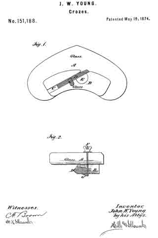
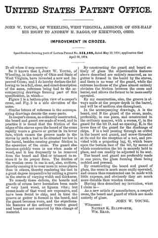
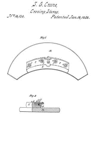
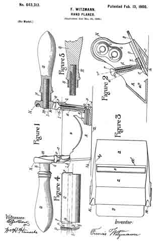
Figure 1 is a front view, partly in section, of a hand-planer embodying my invention. Fig. 2 is a vertical cross-section thereof. Fig. 3 is an inverted plan view of the planer. Fig. 4 is a detail and transverse sectional view of a clamp or wedge, and Fig. 5 is a detail sectional view of the handle.

In the accompanying drawings, in which similar letters of reference indicate corresponding parts in the several views, A indicates a frame of suitable construction, and which is shown provided with a bottom plate a, having a slot or opening a’, opposed side walls a2, and upwardly and outwardly inclined back wall J, upon which a blade B is adapted to rest so thatits lower cutting edge will project into or through the opening a’.
(See Fig. 2.)

C is a clamp or wedge that is adapted to bear upon the blade B to hold the latter in the operative position. Means are provided for retaining the clamp C in such position that its lower beveled edge will aline with and lie near the cutting edge of the blade B, and for this purpose I have shown the clamp C as provided with projections or tongues P, that are adapted to pass into grooves D in the walls a2, which grooves are shown parallel with the walls J and the blade B and above the latter, and the lower ends m, of these grooves form abutrnents, against which the ends l of projections or tongues P rest to regulate the distance that the clamp C can be pushed into the frame. The clamp is held in place so as to create a pressure upon the blade B by means of screws F, which mesh in threaded bores c in lugs d, cast on the inner faces of walls a2 and extending upwardly above the clamp C, the lower ends of these bores c opening above said clamp to enable the ends of the screws F to bear upon the clamp. (See Fig. 2.) The lower parts of lugs d are shown reduced to allow greater freedom for the passage of chips. In line with the bores c the clamp C is provided on its upper surface with countersunk recesses k, into which the tapered ends of the screws F fit.

From the foregoing it will be understood that the clamp C is retained in the lower working position by the projections or tongues P, engaging the abutments m, and that the screws F by entering the recesses k keep the clamp from slipping out of place. By forcing the screws F upon the clamp the latter will hold the blade B rigidly in the cutting position, and by slacking back the screws the pressure of the clamp upon the blade will be reduced and the blade can be readily adjusted more or less into the cutting position to make the desired depth of cut. It will also be seen that when the blade is withdrawn from the frame the clamp will still remain in the working position. As shown, the winged ends of screws F project above the upper edges of the sides a2 of the frame A in position to be readily operated, and the lower edge of the clamp can be seen through the top opening of the frame, whereby as the clamp remains in position it acts as a sight-guide in adjusting the cutting edge of the blade B to a true position transversely of the frame.

The side walls a2 of the frame A are carried high up from the lower wall a, and there is an open space between said walls, as shown in Fig. 1, and to these walls handles G are attached, which extend outwardly in opposite directions. The handles G are thus elevated sufliciently high so that the hands of the operator will not come in contact with the chime of a barrel, keg, or tub when the head of the same is being planed, and by this means practically the entire surface of the barrel-head (except for a slight distance inwardly from the chime) can be planed uniformly and smoothly or a brand or label readily planed or scraped from the same and a perfect command of the tool is afforded. Any suitable means may be provided for attaching the handles to the frame. I have shown a screw or threaded rod H, which meshes in threaded apertures I in the upper portion of the side walls of the frame, and the handles G have threaded apertures that mesh with the screws H, and by preference ferrules N surround the inner ends of the handles and abut, respectively, against shoulders on the handles and against the outer surface of the side walls a2.

The lower edges of the outer sides of the frame A are shown curved, so as to conform somewhat to the curve of the chime or flange of the barrel, keg, or the like whose head or cover is to be planed. (See Fig. 3.)

I do not limit my invention to the details of construction shown and described, as they may be varied without departing from the spirit thereof.

Having now described my invention, what I claim is —

1. In a hand-planer, a frame having an opening in its lower face for a blade and grooves in its side walls parallel to the plane of the blade-seat, combined with a clamp having projecting portions to engage said grooves, the ends of the grooves forming abutments to limit the downward movement of the clamp-plate, and screws carried in threaded apertures in the frame adapted to bear upon said clamp to press the same upon the blade, substantially as described.

2. In a hand-planer, a frame having an opening in its lower face for a blade and grooves in its side walls parallel to the plane of the blade-seat, combined with a clamp having projecting portions to engage said grooves, and provided with recesses on its upper face, the ends of the grooves forming abutments to limit the downward movement of the clamp-plate, and screws carried in threaded apertures in the frame adapted to enter the recesses in the clamp to retain the same in position in the frame and to press the clamp upon a blade, substantially as described.

3. In a hand-planer, a frame having a bottom wall and opposed side walls rising from the same, and means for retaining a blade in said frame, combined with a pair of handles each attached to and projecting laterally from the outer surface of one of said side walls at the top portion of said walls, substantially as described.

In testimony that I claim the foregoing as my own I have hereto affixed my signature in the presence of two witnesses.

FRANCIS WITZMANN.

Witnesses:
GEORGE HILL,
WM. H. HEINECKE.

No. 151,188 – Improvement In Crozes (John W. Young) (1874)

[paiddownloads id=”229″]151188


UNITED STATES PATENT OFFICE.

_________________

JOHN W. YOUNG, OF WHEELING, WEST VIRGINIA, ASSIGNOR OF ONE-HALF HIS RIGHT TO ANDREW H. BAGGS, OF KIRKWOOD, OHIO.

IMPROVEMENT IN CROZES.

_________________

Specification forming part of Letters Patent No. 151,188, dated May 19, 1874; application filed April 30, 1874.

_________________

To all whom it may concern:

Be it known that I, JOHN W. YOUNG, of Wheeling, in the county of Ohio and State of West Virginia, have invented a new and Improved Croze; and I do hereby declare the following to be a full, clear, and exact description of the same, reference being had to the accompanying drawings forming part of this specification, in which —

Figure 1 is a bottom-plan view of a cooper’s croze, and Fig. 2 is a side elevation of the same.

Similar letters of reference in the accompanying drawings denote the same parts.

In cooper’s crozes, as ordinarily constructed, the board and guard are made of wood, and in practice it is found that the friction of the edges of the staves upon the board of the croze rapidly wears a groove or gutter in its lower face, which causes the groove made in the staves by such a tool to be situated too low in the barrel, besides causing greater friction in the operation of the croze. The guard also becomes quickly worn in use when made of wood, and it has frequently to be removed from the board and filed or trimmed to restore it to its proper form. The friction of the wooden croze in use is not, also, uniform, thereby causing it to wear more in some places than in others, thereby rendering the tool in a great degree inoperative by cutting a groove in the staves of varying width and thickness.

To remedy these defects, the boards and guards of crozes have heretofore been made of very hard wood, as lignum vitae; but crozes made of that wood are expensive, and have been found to chip, and in time the groove or gutter is formed in the board, and the guard becomes worn, and the objectionable features of the ordinary wooden guard and board are not removed by this change of material.

By constructing the guard and board entirely of glass the objectionable features above described are entirely removed, as no gutter is formed in the board by the staves, and there is no wear of the guard, while the extreme hardness of the glass almost entirely obviates the friction between the croze and barrel, and allows the former to be more easily operated.

By my construction, also, the groove is always made at the proper depth in the barrel, and will be of uniform size throughout.

In the accompanying drawings, A is the board, and B the guard of the croze, made, preferably, in one piece, and constructed in the ordinary manner, with a recess, C, in the guard for the bit D, and an opening, E, in the lower face of the guard for the discharge of chips. F is a bolt passing through an orifice inthe board and guard, and screw-threaded at its end for the reception of a nut, and provided with a projecting lug, G, which bears upon the bottom face of the bit, by means of which construction the bit is securely held in place, and can readily be adjusted in its seat.

The board and guard are preferably made in one piece, the glass forming them being molded and pressed.

By constructing the board and guard of glass, the croze is much more easily operated, and crozes thus constructed can be made with little expense, and obviously they are much more durable than wooden crozes.

Having thus described my invention, what I claim is —

As a new article of manufacture, a cooper’s croze, the board and guard of which are made entirely of glass.

JOHN W. YOUNG.

Witnesses:
NATHAN K. ELLSWORTH,
WM. READ.

No. 141,828 – Improvement In Crozing And Chamfering Planes (Allen M. Strattan) (1873)

[paiddownloads id=”214″]141828


UNITED STATES PATENT OFFICE.

_________________

ALLEN M. STRATTAN, OF LADOGA, INDIANA.

IMPROVEMENT IN CROZING AND CHAMFERING PLANES.

_________________

Specification forming part of Letters Patent No. 141,828, dated August 12, 1873; application filed March 22, 1873.

_________________

To all whom it may concern:

Be it known that I, ALLEN M. STRATTAN, of Ladoga, in the county of Montgomery, Indiana, have invented an Improvement in Crozing and Chamfering Planes, of which the following is a specification:

This is an improved tool for coopers’ use, and combines the functions of a croze and a charnfering-plane.

Figure 1 is a perspective view of a tool embodying my invention. Fig. 2 is a perspective view of the same reversed. Fig. 3 is a section of my tool taken parallel with the fence-board. Fig. 4 shows my croze-bit detached.

A is a stock and B its fence-board, similar in general conformation to those of a customary chamfering-plane, C being the chamfering-bit and D the wedge. A peculiarly-shaped excavation, E F, in the stock serves as the combined throats of both the chamfering-bit C and a “crow” or crozing-bit, G, whose form is clearly shown in Fig. 4. This crozing-bit is secured by a set-screw, H, tapped into the under side of the stock, and which serves to nip the said bit by its shank I. Embedded into the convex-working face of the stock in advance of, and in line with, the croze-bit G, is a guide bar or tongue, J.

My tool is used in the common way of crozing plows,the fence-board resting upon the edge of the chine and the croze-bit, and chamfer-bit operating simultaneously to both croze and chamfer the chine.

Before using this plane the top of the vessel is leveled by the common block-plane. Then I proceed by placing the chamfering-plane on the top of the vessel, and rotating the plane forward and backward until the croze is cut to a sufficient depth. The chine is finished at the same operation.

I claim as new and of my invention —

The combination of the stock A E F, fence-board B, and bits C and G, when constructed and arranged as herein described to perform the chamfering and crozing operations simultaneously, as explained.

ALLEN M. STRATTAN.

Witnesses:
ISAAC WILLIAM ELLIS,
NATHAN STRATTAN.

No. 80,917 – Improvement In Coopers’ Croze (Charles O. Cook) (1868)

[paiddownloads id=”139″]80917


United States Patent Office.


CHARLES O. COOK, OF ROCKFORD, ILLINOIS, ASIGNOR TO HIMSELF AND R. R. BLAISDELL.

Letters Patent No. 80,917, dated August 11, 1868.
_________________

IMPROVEMENT IN COOPERS’ CROZE.

_________________

The Schedule referred to in these Letters Patent and making part of the same.

_________________

TO ALL WHOM IT MAY CONCERN:

Be it known that I, CHARLES O. COOK, of Rockford, in the county of Winnebago, and State of Illinois, have invented a new and improved Coopers’ Croze; and I do hereby declare that the following is a full and exact description of the same, reference being had to the accompanying drawings, and to the letters of reference marked thereon.

This invention relates to certain improvements in coopers’ croze, and consists in a simple construction of the cutting-iron, whereby it is readily attached to and detached from the adjusting-screw when desired, and yet is securely held when in use, as will be described hereinafter.

Figure 1 represents a plan view of my invention, and
Figures 2, 3, and 4 represent views of parts detached.

In the drawings —

A represents the main part of the instrurncnt, the outer edge of which is curved, to dt the inside of a barrel, and is V-shaped, as shown.

a represents a socket or groove running diagonally across it, in which iits the upper part of the cutting-iron B, which latter is made of proper form to slide easily therein.

b represents an arm extending from the upper end of the cutting-iron B, as shown, upon which is placed the shoulder b1.

b2 represents a flat spring fastened to the lower side of the iron, and extending out in line with shoulder b1.

By this arrangement a socket is made in which rests the button of screw C. The lower or cutting part of the instrument is made V-shaped, for the purpose of cutting the groove in the staves. If desired, this part may be made square in forrn, for the purpose of cutting a corresponding groove.

C represents a screw, the button of which its into the socket of the cutter B, as before described, and revolves freely therein.

c c represent its bearings, provided with corresponding screw-threads. By turning the screw C, the cutter is thrust forward or drawn back, as may be desired.

D represents another screw, placed above the cutter, and operated sirnilarly to C, excepting that it is not attached in any way to the cutter. A bearing-surface of different metal may be used if desired, for the cutter to slide upon, but this is not essential.

This instrument should be attached to the wooden guide, constructed as usual, by means of the lugs x x.

From this description the operation of my invention will be readily understood. The iron is easily attached to the screw by simply pushing the former forcibly against b2 and shoulder b1, in which case the spring b2 yields sufficiently to permit the head of the screw C to pass by the shoulder b1 and rest in the socket. When it is desired to detach the iron for any purpose, its free end should be pulled up from the croze (the holding-screw having been loosened) far enough to force spring b2 open, by which means the head of screw C is permitted to slip out. The cutter B is adjusted in or out, as may be desired, by means of the screw C, after which the screw D is set down upon it, by which means the cutter is rigidly held in place.

This construction allows the cutter to be quickly and easily detached, while at the same time it is firmly held when in use.

Having thus fully described my invention, what I claim as new, and desire to secure by Letters Patent, is —

The arm b, shoulder b1, and spring b2 of cutting-iron B, when combined and operated in connection with the head of screw C, as and for the purpose described.

This specification signed and witnessed, this third day of April, 1868.

CHARLES O. COOK.

Witnesses :
OLIVER A. PENNOYER,
G. W. FORD.

No. 19,130 – Crozing Plane (S.G. Crane) (1858)

[paiddownloads id=”69″]19130


UNITED STATES PATENT OFFICE.

_________________

S. G. CRANE, OF ROCHESTER, NEW YORK.

CROZING-PLANE.

_________________

Specification of Letters Patent No. 19,130, dated January 19, 1858.

_________________

To all whom it may concern:

Be it known that I, S. G. CRANE, of Rochester, in the county of Monroe and State of New York, have invented a new and useful Improvement in Crozing-Planes for Coopers; and I do hereby declare that the following is a full and exact description thereof, reference being had to the accompanying drawings and to the letters of reference marked thereon.

Figure 1, is a plan of the instrument.
Fig. 2, is a transverse section.

The nature of my invention consists in constructing crozing planes with two adjustable circular plates P so arranged as that their radius may be changed to suit barrels, half barrels, &c., and in attaching the knife V to one of said plates P.

The “board” M, I construct in the usual way also the block K. The plates P, are attached to said block by screws J. There are slots in the plates for the screws J to pass through, and they permit the changes shown by the dotted lines in Fig. 1. The slots are covered by the Washers C.

The knife V is attached to the rear plate P by the screw Y and its nut D. Said nut is a flat plate of about the same size as the shank of the knife, and answers as a gage for the depth of cutting when the plates are set out for smaller circles, as seen in Fig. 1 by the dotted lines, and at such times the knife V requires no readjusting, it being adjusted to the rear plate, is moved with it.
The spur B on the rear plate answers as a gage for the other plate.

What I claim, is —

The construction and arrangement of the adjustable plates P, and the arrangement of the knife V, as, and for the purposes specified.

S. G. CRANE.

Witnesses:
FERDINAND SEIFRIED,
LOUIS ERNST.