No. 1,026,636 – Plane (Christian Bodmer) (1912)

UNITED STATES PATENT OFFICE.
_________________
CHRISTIAN BODMER, OF NEW BRITAIN, CONNECTICUT, ASSIGNOR TO THE STANLEY RULE &
LEVEL COMPANY, OF NEW BRITAIN, CONNECTICUT, A CORPORATION OF CONNECTICUT.
PLANE.
_________________
1,026,636. Specification of Letters Patent. Patented May 14, 1912.
Application filed July 26, 1911. Serial No. 640,618.
_________________
To all whom it may concern:
Be it known that I, CHRISTIAN BODMER, a citizen of the United States, residing at New Britain, county of Hartford, State of Connecticut, have invented certain new and useful Improvements in Planes, of which the following is a full clear and exact description.
My invention relates to an improvement in planes, the object of the invention being to provide a simple and efficient plane construction which may be used for the purpose of accurately truing up or squaring up the edges of boards. Where heretofore various more or less complex constructions, including separate attachments, have been provided in conjunction with plane bodies for accomplishing this purpose, in the present invention the plane body itself is of unique construction, being integral throughout, the handle portion being so arranged that the pressure applied to the plane is in such a direction relatively to the work being done that said plane naturally seeks a true position upon the board being planed.
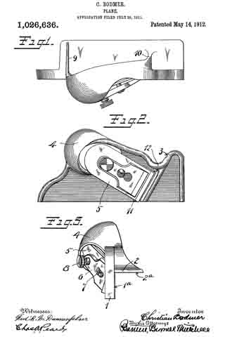
In the drawings Figure 1 is a plan view of the plane complete, ready for use and practically full size. Fig. 2 is a side elevation thereof. Fig. 3 is a front end elevation.
The frame is made of a single body casting and comprises two right-angle side fianges 1–2, which furnish the two right-angle bearing faces 1a–2a respectively. The flange 1 is continued upwardly at its front end to form an inclined and rearwardly facing thumb-rest 3. To the rear of the thumb-rest 3 and back of the middle line of the plane is a palm-rest 4 formed by a cross-web or flange set at an angle on the upper end of flange 1 and projecting above flange 2. This palm-rest is bulged to conform to the palm of the hand, so that the position of the hand upon the plane body will be such that pressure applied will cause both bearing surfaces 1a–2a to press uniformly upon the surface and edge of the board being planed. Upon the outer side of the plane is supported at a proper angle a cutter 5. The side flange 1 is provided with a throat, preferably oblique, in which throat the cutting edge of the plane iron or cutter 5 stands.
6 is a cap detachably held at the middle by the usual screw 7. 8 is a clamp screw at the rear of the cap, for causing said cap to properly engage the cutter to hold it tightly upon its support and in its properly adjusted position. The palm-rest 4 is preferably connected with the flange 2 by means of flanges or ribs 9–10, formed by widening the ends of the cross-web and which serve to rigidly hold the two flanges against distortion.
11 is a lug to support the cutter at its side edge to prevent it from turning during the progress of the work. The width of the cutter is such that it extends the full width of the bearing surface 1a.
12 is a reinforcing rib, which bridges the plane body at the end of the throat in which the cutter stands, so as to stiffen the same at this otherwise weakened point, due to forming the throat. The rib 12 is preferably extended around the forward end of the plane and also rearwardly back to the bulged palm support or bearing.
What I claim is :–
1. As an article of manufacture, a one-piece metal casting forming the body of a plane and comprising a work collocating tool guiding flange and a slotted tool carrying flange extending therefrom and forming a right angle, and an integral palm rest arranged at the rear end of said casting extending outwardly from and obliquely to the line of junction of said flanges and formed by a cross-web or fiange set at an angle on the upper edge of the tool carrying flange and which projects above the first mentioned flange.
2. As an article of manufacture, a one-piece metal casting forming the body of a plane and comprising a work collocating tool guiding flange and a slotted tool carrying flange extending therefrom and forming a right angle, and an integral palm rest arranged at the rear end of said casting extending outwardly from and obliquely to the line of junction of said flanges and formed by a cross-web or flange set at an angle on the upper edge of the tool carrying flange and which projects above the first mentioned flange, the ends of said web being widened to form flanges across the latter flange.
CHRISTIAN BODMER.
Witnesses:
JOSEPH M. HANCE,
CLARENCE L. BENEDICT.
Copies of this patent may be obtained for five cents each, by addressing the “Commissioner of Patents, Washington, D. C.”
_________________