No. 766,491 – Plane (Albert William Campbell) (1904)

[paiddownloads id=”607″]766491


UNITED STATES PATENT OFFICE.

_________________

ALBERT WILLIAM CAMPBELL, OF GLASTONBURY, ENGLAND, ASSIGNOR TO THE STANLEY RULE & LEVEL COMPANY, OF NEW BRITAIN, CONNECTICUT, A CORPORATION OF CONNECTICUT.

PLANE.

_________________

SPECIFICATION forming part of Letters Patent No. 766,491, dated August 2, 1904.
Application filed February 19, 1904. Serial No. 194,429. (No model.)

_________________

To all whom it may concern:

Be it known that I, ALBERT WILLIAM CAMPBELL, a citizen of Great Britain, residing at Glastonbury, in the county of Somerset, England. have invented certain new and useful Improvements in Planes, of which the following is a full, clear, and exact description.

My invention relates to improvenients in planes, and particularly to adjusting mechanism for double-ended planes.

The object of the invention is to provide a simple and inexpensive means for adjusting the plane-iron in a double-ended plane, which adjusting means shall be reversible to cooperate with the plane-iron in either its front or rear position, so as to vary the cutting depth when desired.

The invention consists in providing, first, a plane-body having two openings or throats in the sole portion and supports for the plane-iron for both of these throats; second, a plane-iron and a clamping member with means for holding them in place; third, adjustable and reversible means for projecting or retracting the plane- iron through either one of the throats, as desired.

The details of my invention will be more clearly seen on an inspection of the accompanying single sheet of drawings, in which —

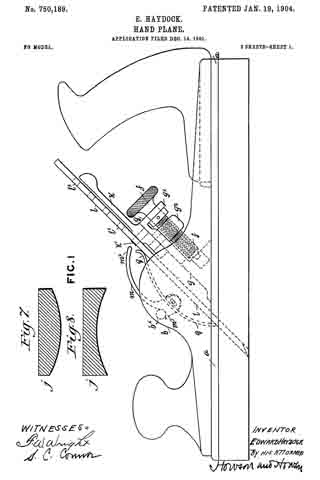
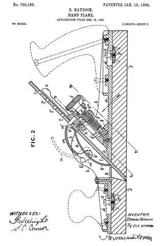
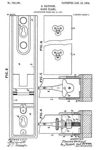
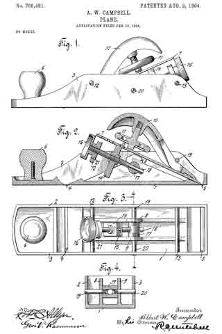
Figure 1 is a side elevation of a plane embodying the improvements of my invention, the plane-iron being projected through the forward throat. Fig. 2 is a central longitudinal section of the plane with the iron projected through the rear throat. Fig. 3 is a plan view of the plane-body and the adjusting mechanism in the position of Fig. 2, the plane-iron and clamp being removed. Fig. 4 is a vertical cross-section taken on the plane of the line 4 4, Fig. 3.

1 indicates the sole portion of the plane. 2 and 3 are the side flanges which reinforce and strengthen the same 4: is the front throat or opening through which the cutting edge of the plane-iron may project.

5 is the rear throat.

6 is a handle which may be conveniently provided at the fore end of the plane.

7 is a plane-iron which at its cutting edge is supported by a portion of the sole.

8 and 9 are supports for the plane-iron 7 intermediate the throats 4; and 5.

10 is a cap member which bears against the plane-iron near the lower end.

11 is a clamping member carried by the cap which coacts with the plane-iron.

12 and 13 are cross-bars supported by the flanges 2 and 3 of the plane. The cap is inserted beneath one of these cross-bars, and the clamp 11 holds the parts in place.

14 is an adjusting-block having a projection 15 at the upper end for coacting with a recess or perforation in the plane.-iron.

16 is an adjusting-screw for coacting with the adjusting-block to move it back and forth, so as to vary the cutting depth of the plane-iron.

17 is a pivoted step for the adjusting-screw.

18 is a washer over which the lower end of the adjusting-screw is riveted to hold the same in place, so as to prevent the adjusting-screw from moving longitudinally with relation to the step 17.

19 and 20 are pivot-screws which extend through the side flanges 2 and 3 and also through the supports 8 and 9 and are screwed into the step 17. The lower end of the adjusting-block is guided between the inner faces of the supports 8 and 9, and thus prevented from rotation with respect to the adjusting-screw. The rotation of the adjusting-screw thus causes longitudinal movement of the plane-iron.

21 is a wheel or roller carried by the adjusting-screw 16, which rests upon the cross-bar 12 when the parts are in the position shown in Fig. 2. This supports the adjusting-screw toward the upper end. Of course when the plane-iron is reversed the cap 10 is inserted under the rod 12 and the wheel 21 rests on the rod 13, the adjusting and clamping means being reversible and interchangeable in this respect.

It will be obvious to one skilled in the art that many changes and alterations might be made in the construction shown in the drawings without departing from the spirit or scope of my invention.

What I claim is —

1. In a double-ended plane, a body portion having two throats, a plane-iron and reversible means for adjusting the cutting depth of the iron at either throat.

2. Adouble-ended plane comprising a body portion having two throats, a plane-iron and a pivoted reversible means for adjusting its cutting depth of said plane-iron through either of said throats.

3. A plane comprising the combination of a body portion with two throats, a step, pivots therefor, a screw coacting with said step and an adjusting-block operated by said screw.

4. In a plane, a body portion having side flanges and two throats in the sole, a plane-iron, clamping means therefor, two rods connecting said flanges, supports between said throats for said iron, a step, an adjusting-screw for said iron coacting with said step and adapted to coact with either one of said rods for support.

5. In a plane, a. body portion having two throats, supports between said throats, a plane-iron, a reversible adjusting-block therefor, a guide for said block to the rear of each throat to prevent its rotation and a screw coacting with said block for the purpose specified.

6. In a plane, a body having two throats, two supports therein, a plane-iron, a step pivotally mounted between said supports, an adjusting-block, and a screw coacting with said step and said block.

Signed at Shepton Mallet, in the county of Somerset, England, this 4th day of February, 1904.

ALBERT WILLIAM CAMPBELL.

Witnesses:
P. MAGGS,
T. E. RUSSELL.

No. 750,189 – Hand-Plane (Edward Haydock) (1904)

[paiddownloads id=”597″]750189


UNITED STATES PATENT OFFICE.

_________________

EDWARD HAYDOCK, OF MANCHESTER, ENGLAND.

HAND-PLANE.

_________________

SPECIFICATION forming part of Letters Patent No. 750,189, dated January 19, 1904.
Application filed December 14, 1901. Serial No. 85,900. (No model.)

_________________

To all whom it may concern:

Be it known that I, EDWARD HAYDOCK, a subject of the King of Great Britain, residing at 75 Ackroyd street, Higher Openshaw, Manchester, in the county of Lancaster, England, have invented a new and useful Improved Hand-Plane, of which the following is a specification.

This invention relates to hand-planes for woodworking, particularly pattern-making, in which curves and other irregular forms are required to be produced in patterns and core-boxes and other like work.

The object of my invention is to enable plane-irons with diiferent forms of cutting edges to be employed in a metallic stock having a flat sole in combination with a wood sole that is capable of being fixed to or removed therefrom, whose face is either formed to any preferred curve or of other required shape, and to provide means for holding said sole firmly in position; also, quick and automatic adjustment of the plane-iron.

In the accompanying drawings, illustrating my invention, and to which I hereinafter refer, Figure 1 is a side view, and Fig. 2 a longitudinal section, of my improved plane. Fig. 3 is a plan of the stock-sole with the plane-iron and adjustments removed. Fig. 4 is an angular transverse section on line A B, and Fig. 5 a like section on line C D as seen in the direction of the arrow in Fig. 2. Fig. 6 is a plan of adjustable sole. Fig. 7 is a cross-section of a detachable convex wood sole for planing the inside of a cylinder, while Fig. 8 is a view of a concave sole for planing the outside of cylindrical bodies.

In the views the same letters refer to like parts.

According to this invention I form a metallic stock of malleable iron or steel, either cast or pressed, or other preferred metal, having key-shaped holes therein, as shown at d on plan in Fig. 3. These holes, are for the reception of small studs or set-screws c, which are fastened in small castings, as c’, fixed in an adjustable wood sole, as j. (Shown in Figs. 2 and 6.) The position of these castings in the adjustable sole corresponds with the holes in the stock-sole a. The facing on the upper side of the key-shaped holes d in the stock-sole is slightly taper to insure the screws c drawing the adjustable sole perfectly tight and rigid to the stock-sole when it is fitted thereon. The adjustable soles may be flat for ordinary smooth, jack, or trying plane purposes, or they may be of any required shape or radius for curves, core-boxes,or like work, as shown in Figs. 7 and 8. I fix a triangular slide g between the side walls b of the stock by means of screws inserted in the stock-sole.

The holes for the screws are slightly elongated to permit the slide to be moved a little backward or forward in order to alter the pitch of the plane-iron for planing different kinds of wood, either with or across the grain, as required. The aforesaid slide has a slot g’ formed lengthwise in its angular face, through which a square-headed stud g2 is passed. Said stud is square under the head and has a hole through the head, with a screw-thread formed therein. The projecting end of the stud is screwed or loosely riveted into a carrier or adjusting-lever k, which carries aplane-iron, as l, by means of a pin k’, that enters one of the small holes l’, formed at equal distances along the center of the plane-iron if a single iron is employed for radii or curved work or into a small hole in the back iron for ordinary planing. The aforesaid stud, with the plane-iron, is raised and lowered by a screw f, which is passed through the head of the stud g2, the neck of the screw being held in a lug gx at the top of the slide g and the bottom end resting in a footstep in said slide. The plane-irons are set square by the adjusting-lever k being turned a little to one side or the other and are held firmly in position by a curved spring q, the ends of which are pressed against the face of the plane-iron by a cam-lever m, the lower end of which is formed with a curved projection m’ at each side and hinged to the center of the aforesaid spring, as shown at qx in Fig. 2. A lug bx projects inwardly from each of the side walls of the plane, under which the curved projections m’ are placed when the lever m is in the position shown by dotted lines. When the free end mx of the lever is turned down, as shown, the spring q is compressed and the ends pressing on the face of the plane-iron keep it firmly in position, perfect and rapid means of adjustment being thereby obtained. The mouth of the plane if employed as an ordinary metallic plane without wood soles may be enlarged or reduced by a metallic slide p, fitted to the stock-sole by a stud passing through an elongated hole and secured by a nut. By these means a direct positive motion is obtained for forward feed and lateral adjustment of plane-iron, and if one iron is, ground to a two and one-half inch radius it would also work to any radius extending to about four inches without regrinding or altering. A quarter of a turn of the screw f would give one one-hundred-and-twelfth part of an inch, or thereabout, forward adjustment of the plane-iron, and by the lateral adjustment the inconvenience of exercising great care in sharpening or grinding the iron to correct form is avoided.

A sole-plate to do any kind of special work that is usually done by special planes may be made by the workman himself and fixed in the manner described for use as an ordinary smooth, jack, or trying plane.

I claim as my invention —

1. A hand-plane consisting of a metallic stock with keyhole-slots in the stock-sole, the enlarged opening of the keyhole being toward the front of the stock-sole, wooden soles carrying screws adapted to be passed through the keyhole-slots and inclined wedge-surfaces on one of the parts, whereby, upon forcing the metal stock forward the wooden sole will become secured to the metallic stock and by striking the rear of the sole it will become detached, substantially as described.

2. A hand-plane having a metallic stock with a flat sole-face, elongated recesses in said sole and a number of separate wood soles, each having a fiat surface and projections thereon adapted to fit into aforesaid recesses, the projections fitting the forward portion of said recesses loosely and fitting the rear portion tightly so that the sole may be slid against the surface of the stock to secure the wood sole to the metallic stock, whereby on striking the rear of the sole it will become detached, substantially as described.

In testimony whereof I have signed my name to this specification in the presence of two subscribing witnesses.

EDWARD HAYDOCK.

Witnesses:
THOS. PRESCOTT,
JNO. HUGHES.

No. 707,085 – Recessing Or Grooving Plane (Fred Clayton) (1902)

[paiddownloads id=”567″]707085


UNITED STATES PATENT OFFICE.

_________________

FRED CLAYTON, OF PUDSEY, ENGLAND.

RECESSING OR GROOVING PLANE.

_________________

SPECIFICATION forming part of Letters Patent No. 707,085, dated August 19, 1902.
Application filed April 1, 1902. Serial No. 100,915. (No model.)

_________________

To all whom it may concern:

Be it known that I, FRED CLAYTON, a subject of the King of Great Britain and Ireland, residing at Pudsey, near Leeds, in the county of York, England, have invented a new and useful Recessing or Grooving Plane, of which the following is a specification.

My invention relates to an improved recessing or grooving plane in which various tools are interchangeable in various positions in the plane according to the nature and situation of the work required to be done, such plane being applicable for planing the bottom and sides of grooves in woodwork — such, for instance, as grooves in hoist-slides, grooves in collapsible boxes, shelf-grooves in cupboard sides, step-grooves in staircase sides, grooves in the sides of core-boxes for the ends to fit into, and grooves in patterns in to which lifting-irons, fillets, or ribs are recessed. It is applicable also for planing out the bottom of panels and all other depressions or recesses below the general surface of the wood-work.

My invention is illustrated in the accompanying drawings, in which —

Figure 1 is a plan, Fig. 2 an end view, and Fig. 3 a side view, of my improved plane, showing a right-hand side tool in position for use. Fig. 4 is a plan of regulating or adjusting slide for right-hand side tool. Fig. 5 is a plan and Fig. 6 a side view of regulating or adjusting slide for left-hand side tool. Fig. 7 is a plan and Fig. 8 a side view of bottom tool. Fig. 9 is a plan and Fig. 10 an end view of loose collar and screw by which the various tools are secured in position. Fig. 11 is an end view, and Fig. 12 a side view, of right-hand side tool. Fig. 13 is a side view, and Fig. 14 an end view, of left-hand side tool.

Similar letters refer to similar parts throughout the several views.

My improved plane consists of a frame or body B, preferably having two handles C C and fitted with five vertical tool-posts A’ A2 A3 A4 A5 in suitable positions on the said frame or body B. A right-hand side tool D, Figs. 1, 11, and 12, a left-hand side tool E, Figs. 13 and 14, and a bottom tool F, Figs. 7 and 8, are provided, the side tools D and E being fitted in the posts A’ and A2, respectively, and the bottom tool F being interchangeable in the tool-posts A3 A4 A5. The tools are held in position in the desired post so as to be adjustable vertically therein by means of a loose collar G, having thumb-screw H.

A right-hand slide K for use with the side tool D may be fitted beneath the frame or body B of the plane, this slide being secured and adjusted by means of pin M and screw N, working within a pair of parallel oblique slots P P in the frame or body B. The cutting-tool D when in position passes through a side opening R in the said slide K, the amount of cut being regulated by tapping the slide at the ends. A similar left-hand slide L is provided for use with the side tool E, this slide having side opening R’ and being similarly secured by pin M’ and screw N’, working within a second pair of parallel oblique slots P’ P’. These slides K L are removed when not required by slackening the irrespective screws N N’ and, withdrawing the pins M M’ and screws N N ’ from their respective slots, a suitable opening S in the frame being provided to allow for the insertion and withdrawal of the screw-heads. By this means the plane can he adapted to a large variety of work, the required tool being fixed in the post best suited to the purpose. Thus for planing the sides of grooves or recesses the tools D and E would be employed, fixed in the post A’, as shown in Figs. 1, 2, and 3, and in the post A2, respectively. For general purposes of planing out the bottom of grooves the tool F would be fixed on the inside of the post A3. For work in which the tool is required to go in advance of the plane the tool would be fixed on the outside of the post A3. Where the work operated upon is short and the recess deep the tool would be fixed in the post A4, so as to obtain bearing-surface both in front of and behind the tool. For work in which the tool is required to follow the plane — as, for instance, in half-lapping-the tool would be fixed in the post A5.

T represents holes for screws for attaching a curved piece of wood to the bottom of the plane-body when desired.

What I claim is —

1. The combination, with a plane-body provided with a series of separate tool-posts arranged in different planes, of a clamp for securing tools to the said posts, substantially as set forth.

2. The combination, with a plane-body provided with separate tool-posts arranged in different planes and having also oblique slots, of an adjustable slide provided with fastening devices which engage with the said slots, and a clamp for securing tools to the said posts, substantially as set forth.

3. The combination, with a plane-body provided with separate tool-posts arranged in different planes and having also two pairs of oblique slots for right and left hand side tools provided with fastening devices which engage with the said slots, and a clamp for securing the tools to the said posts, substantially as set forth.

In testimony whereof I have signed my name to this specification in the presence of two subscribing witnesses.

FRED CLAYTON.

Witnesses:
ALLAN BENNETT,
LEWIS DEXTER.

No. 649,090 – Plane-Handle (John Henry Webb) (1900)

No. 649,090 – Plane-Handle (John Henry Webb) (1900)

[paiddownloads id=”547″]649090


UNITED STATES PATENT OFFICE.

_________________

JOHN HENRY WEBB, OF CARDIFF, ENGLAND.

PLANE-HANDLE.

_________________

SPECIFICATION forming part of Letters Patent No. 649,090, dated May 8, 1900.
Application filed July 10, 1899. Serial No. 723,413. (No model.)

_________________

To all whom it may concern:

Be it known that I, JOHN HENRY WEBB, of Riverside, Cardiff, England, have invented certain new and useful Improvements in or Relating to Handles for Planes and other Tools, of which the following is a full, clear, and exact description.

In carrying out my invention I provide a handle of suitable material which is attached to the plane in any convenient position by means of grooves or such like. I provide strengthening brackets or supports. In ordinary plane-handles these are cut from wood in the solid and are mortised into the plane-block; but by my invention this handle may be attached to the block without cutting the block, it being merely necessary to secure the handle to the supports which are attached to the plane-block.

For purposes of illustration I will now refer to the annexed drawings, in which —

Figure 1 is a side elevation showing my invention applied to a plane, and Fig. 2 a plan view of same.

a, is a plane-block to which the brackets b and d are attached by means of the screws g and f, the bottom bracket d being recessed, as indicated by the dotted lines. The handle c is secured between the brackets b and d by means of the screw e, which passes through the top bracket b, through the handle c, and is then screwed into the bracket d, thus securing the handle c in position.

Having thus described my invention, what I claim, and desire to secure by Letters Patent, is —

In means for attaching handles to plane-blocks, in combination, two brackets secured by means of screws to the plane-block, one upon the end thereof and the other upon the adjacent top of the plane-block; a handle of suitable material adapted to engage between said brackets, a screw passing through top bracket and handle and engaging in the bottom bracket for the purpose of securing the handle in position, a recess in said bottom bracket for the reception of said handle, substantially as described and illustrated herein and for the purpose set forth.

In testimony that I claim the foregoing I have hereunto set my hand this lst day of April, 1899.

JOHN HENRY WEBB.

Witnesses:
JAMES SLEVIN,
WILLIAM JOHN WEEKS.

No. 512,147 – Rabbeting-Plane (William Beddows) (1894)

[paiddownloads id=”500″]512147


UNITED STATES PATENT OFFICE.

_________________

WILLIAM BEDDOWS, OF NOTTINGHAM, ENGLAND.

RABBETING-PLANE.

_________________

SPECIFICATION forming part of Letters Patent No. 512,147, dated January 2, 1894.
Application filed August 27, 1892. Serial No. 444,288. (No model.) Patented in England January 28, 1892, No. 1,736.

_________________

To all whom it may concern:

Be it known that I, WILLIAM BEDDOWS, a subject of the Queen of Great Britain and Ireland, residing at Nottingham, in the county of Nottingham, England, have invented new and useful Improvements in Rabbeting-Planes, (for which I have obtained a patent in Great Britain and Ireland, No. 1,736, bearing date 28th January, 1892,) of which the following is a specification.

My invention relates to improvements in side planes or those planes wherein the cutting edge of the iron or bit lies at the side, as contradistinguished from the bottom of the plane stock, and the object of said invention is to provide a plane of the class mentioned which is adapted to smooth the side walls of narrow grooves, quirks and beveled shoulders in wood work and which is constructed in a novel manner, whereby the edge of the iron or bit will give a clear cut, the iron being firmly bedded, fiat, and of a form capable of being sharpened and adjusted in the stock, so as to be used for a long period of time.

To these ends the invention consists in the novel construction and combination of parts hereinafter described and claimed, reference being had to the accompanying drawings, wherein —

Figure 1, is a side elevation of a plane constructed according to my invention. Fig. 2, is an end elevation thereof. Fig. 3 is a cross sectional view taken on the line x–x Fig. 1. Fig. 4 is a plan view, the iron or bit and its retaining devices being removed. Figs. 5 and 6, illustrate, respectively, a face and an edge view of the plane iron or bit. Fig. 7 is a detail vertical sectional view of the iron or bit retaining plate. Figs. 8 and 9 are, respectively, plan and end views illustrating a different arrangement. Figs. 10, 11 and 12, illustrate, respectively, plan, edge, and end views of a triangular plane iron or bit. Figs. 13 and 14, illustrate, respectively, a side view and a longitudinal section of a construction particularly adapted for curved work. Fig. 15, is a detail transverse sectional view, illustrating another arrangement. Figs. 15a, 16 and 17, illustrate, respectively, a side elevation, an end view and a plan view of a further different arrangement. Figs. 18 and 19, are sectional views, taken, respectively, on the lines 18–18 and 19–19, Fig. 15a.

In said drawings the reference letter a designates the plane stock or body which is substantially triangular in section and of narrow dimensions transversely or in width and which is provided with a vertical working side face, the width of the upper part of the stock being comparatively large, so as to form a firm and strong bed or support for the iron and to give rigidity to the tool, while the lower part is extremely narrow and may be only one-tenth or one-twentieth of an inch in transverse section, so as to permit its entrance into narrow grooves in wood-work, to plane or smoothen the side walls of such grooves. Said stock is provided with an iron or bit-receiving channel b which extends from the top to the bottom of the stock a in an inclined, forward direction, as best shown in Figs. 1, 13, 15a and 20, of the drawings, and which also slants laterally, or extends in a transversely inclined direction from its commencing end b’ to its finishing end f.

In order to employ an iron or bit of flat form and having the advantages above described, in a stock which has an inclined mouth, that is to say, a mouth making any angle say from ten degrees to eighty-nine degrees with the bottom or riding edge of the plane, the iron or bit and its channel or bed are so inclined or canted with respect to the face or side of the plane stock as indicated by the reference letter b3, as to bring the cutting edge of the iron in the mouth when the iron or bit is in place in said channel. This will be better understood by reference to Figs. 1 to 6 and 15 to 19 of the drawings which show stocks with the mouth inclined at angles less than ninety degrees and by reference to Fig. 13, which represents a stock with the mouth at ninety degrees to the bottom or riding edge.

The reference letter c indicates the plane iron or bit having a cutting edge g formed at an angle with the side edge of the said iron or bit, the cutting end being of the same thickness as the remainder of the iron or bit and with a top beveled cutting edge, that is to say, the cutting edge when in place in the mouth slants away from the face, the fiat or unbeveled side of the iron being toward the bed, so that a thin or thick shaving may be produced and the acuteness of the cutting edge increased or decreased in sharpening as desired, the shavings being similar to those produced by ordinary surfacing planes in contradistinction to planes for cutting cigar lighters which have an inclined iron in a more or less rectangular stock and are designed to produce a shaving of a special form, and which cannot be used for surfacing, and which is adapted to be placed in and removed from the channel b, and when in operative position in said channel its cutting edge lies in the rearwardly inclined finishing end f of said channel.

The mouth f of the stock may be at any desired angle with respect to the bottom edge of the plane, the angle being different according as the plane is intended for surfacing soft, fibrous or hard woods, and as it is desired that the iron shall have a more or less shear cut.

The plane iron or bit c is firmly retained in position in the channel b as illustrated in Figs. 1, 2 and 3, by means of a retaining plate d which lies over the channel b and is provided with a flange d’ which bears upon the plane iron or bit c when it is forced in the proper direction by the screw e which passes through an orifice in said plate and has a screw-threaded engagement with the plane stock; a, as clearly shown.

In Fig. 15, I have shown the retaining plate held in place by a bolt e’ passing therethrough and through the stock a, a nut e2 engaging the end thereof, by turning which nut the retaining plate is tightened to clamp the plane iron or bit in place, or loosened to permit its removal.

In Figs. 8 and 9, the plane iron or bit c is shown retained in place by means of a wedge h, the retaining plate d, and its screw or bolt being dispensed with. In this construction the upper part of the stock a is enlarged so as to receive the plane iron or bit and wedge, the wedge being driven into place in the channel to forcibly hold the iron or bit within the channel.

In Figs. 10, 11 and 12 a plane iron or bit c’ is shown triangular in cross section so that it will accurately fit and fill the channel b, which is also triangular in cross section.

A plane particularly adapted for curved work is illustrated in Figs. 13 and 14 wherein the dimensions of the bottom edge of the stock a’ are greatly reduced. In these figures I have also shown a different arrangement of devices for retaining the plane iron or bit in place, that is to say, a retaining lever j and thumb screw k, the fulcrum of the lever being a bar, bridge or pivot l, fixed to or cast in one piece with the stock a’, as shown in section Fig. 14.

In Figs. 15a to 19, I have shown other means for retaining the plane iron or bit in place, wherein the letter a indicates the plane stock; b, the channel and c, the plane iron secured in the channel by the retaining block d3 and screw e3 which engages the screw socket in the retaining block d3 and bears at its inner end against the plane iron c.

It will be understood that the degree of inclination possessed by the channel b herein described may be varied to suit different conditions without departing from the scope of my invention, and that a side rabbeting plane having a stock wide at the top and narrow at the bottom so as to be capable of entering narrow grooves and yet forming a strong, firm support for a single, flat or triangular section top beveled adjustable iron or cutter, which lies in the bed of the stock which bed is inclined from top to bottom and also slants transversely of the stock and is capable of being easily clamped or secured in position in said bed, may be made with the bottom or riding edge of various lengths according as the tool is intended for straight or curved work, for rough or fine work, and also that the mode or means of clamping the iron or bit may be varied, the wedge as in Figs. 8 and 9 being preferable for deep narrow grooves and the means shown in Figs. 1, 2, 3, 13,15, 16, 17, and 18 being more desirable for shallow grooves or large work. For this reason three methods of clamping are shown and described. The plane stock is so shaped at its upper part as to be easily held in the hand of the user.

Having thus described my invention, what I claim is —

1. In a plane, the combination with a transversely narrow stock, having a vertical working side face, and provided with a channel which is inclined from top to bottom of the stock and slanted transversely of the stock, and one side wall of which is canted, whereby said channel terminates in a rearwardly inclined opening in the vertical working side face of said stock, of a plane iron located in said channel with its cutting edge lying in a rearwardly inclined direction with respect to the working face of the stock, and means for holding said plane iron in position, substantially as described.

2. In a side rabbet plane, the combination with a channeled plane stock of substantially triangular section and having a slit or mouth in the vertical side face thereof, of a uniform iron or cutter having a top beveled cutting edge angularly to the sides of the iron or cutter, and devices for holding said iron or cutter in position, substantially as described.

In witness whereof I have hereunto signed my name in the presence of two subscribing witnesses.

WILLIAM BEDDOWS.

Witnesses:
EDW. D. HEARN, Junr.,
6 Victoria Street, Nottingham.
ISAAC GALE.