No. 984,083 – Floor-Plane (William J. Faber) (1911)
[paiddownloads id=”676″]984083


UNITED STATES PATENT OFFICE.

_________________

WILLIAM J. FABER, OF ONEIDA, NEW YORK.

FLOOR-PLANE.

_________________

984,083. Specification of Letters Patent. Patented Feb. 14, 1911.
Application filed March 28, 1910. Serial No. 551,829.

_________________

To all whom it may concern:

Be it known that I, WILLIAM J. FABER, of Oneida, in the county of Madison, in the State of New York, have invented new and useful Improvements in Floor-Planes, of which the following, taken in connection with the accompanying drawings, is a full, clear, and exact description.

This invention relates to certain improvements in floor planes for smoothing floors and other wood surfaces.

ln the use of ordinary planes the cutting blade is previously set or adjusted to produce the desired depth of cut and remains in this position until readjusted to vary the depth of the cut and under such conditions, preferably in smoothing the surface of hard wood, it is extremely difficult to start the plane on its initial movement owing to the fact that immediately upon the beginning of such movement the cutting edge is embedded to the full depth of its adjustment into the wood, thereby requiring considerable power to move the plane forward. Furthermore under the same conditions when the plane is drawn backward, the cutting edge is allowed to drag or ride over the surface of the floor, thereby producing excessive wear and more or less dulling effect upon such edge, and making it necessary to frequently regrind or re-sharpen the same.

The main object of my present invention is to provide means whereby the cutting edge of the blade will be held clear of the surface of the floor during the initial forward movement and will be gradually forced to its cutting position as the plane advances, thereby enabling the operator to move the plane forwardly under comparatively light pressure or force or until under sufficient momentum to permit the plane to be carried to the limit of its forward stroke with a minimum amount of power. In other words, the object sought is to cause the cutting edge of the blade to automatically clear the surface of the floor during the backward stroke and to be gradually moved to its cutting position during the forward stroke, so as to allow the plane to be moved through the complete forward stroke with a minimum degree of power and at the same time relieving the cutting edge from undue wear during the backward stroke.

Other objects and uses relating to specific parts of the device will be brought out in the following description.

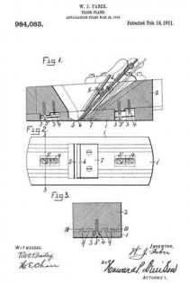
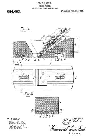
In the drawings: Figure 1 is longitudinal sectional view of a plane embodying the various features of my invention. Fig. 2 is an inverted plan of the same. Fig. 3 is a transverse sectional view taken on line 3-3-, Fig. 2.

This plane comprises a base section –1– and a stop section –2– resting upon and movable relatively to the base section. The meeting faces of said sections are inclined rearwardly from the front end and are therefore disposed at an angle with the bottom of the base section –1– which is substantially flat. The object of the inclined meeting faces is to permit a slight vertical movement of the section –2– as the plane is moved forward and backward. The upper section –2– is adapted to be engaged by the hand of the operator and it therefore follows that during the operation of moving the plane forward the upper section will be moved down the incline or slightly lowered, while the backward movement will similarly elevate the top section. These sections –1– and –2– are limited in their relative endwise movement by suitable stops –3– consisting in this instance of bosses which are projected into elongated slots –4– near the front and rear ends respectively of the base section –1– and formed with threaded apertures in the under side of the top section –2–. The slots –4– are enlarged at the bottom to receive the heads of screws –3’– and to form shoulders against which said heads abut to hold the meeting faces of the sections –1– and –2– in sliding contact, the heads of the screws being wholly within the lower surface of the section –1– to prevent contact with the surface which is being planed. This lower section –1– is also provided with a comparatively narrow knife opening –5– through which the cutting edge of a knife blade, as –6–, is movable and adapted to protrude when in operative position, the lower surface of the section –1– just back of the cutting blade being reinforced by a metal plate –7–. The cutting blade –6– is adjustably mounted in and upon the upper section –2– where it is locked or held in its adjusted position by a set screw –8– or other suitable fastening means, not necessary to further illustrate or describe, it being understood that any well known fastening means common in this art may be employed for this purpose which will enable the blade to be adjusted so that its cutting edge protrudes more or lesss through the opening –5–.

The plane is operated back and forth by the engagement of one or both hands of the operator upon the upper section –2– and owing to the fact that this section is movable relatively to the lower section –1– it is apparent that as the plane is drawn back the upper section will be moved up the incline of the lower section a distance corresponding to the length of the slots –4– or until limited by the engagement of the limiting stops with the rear ends of the slots thereby elevating the cutting edge of the blade –6– above the lower face of the plane section –1– whereupon the continued backward movement of the upper section of the plane effects a corresponding backward movement of the lower section –1–, as soon as the limiting stops –3– engage the rear ends of the slots –4–, it being understood that when the cutting blade is in its lowermost position the protrusion of its cutting edge will not exceed the degree of rise of the incline for the length of the slot. In moving the plane forward for the cutting operation assuming that the upper section is then in its extreme backward position or at the highest point of incline, the upper section will be initially or first moved down the incline and relatively to the lower section until the cutting edge of the blade is brought into engagement with the surface to be planed or until the limiting stops –3– engage the front ends of the slots –4– whereupon both sections will be moved forwardly together. This initial movement of the upper section –2– relatively to the lower section –1– requires but little strength or force and enables the operator to get the plane under head-way or momentum before the cutting edge of the blade is embedded to its maximum degree of adjustment into the wood and therefore this momentum aids the operator in forcing the plane through its forward stroke during the cutting operation, thereby reducing the power required to operate the plane from one extreme to the other of its cutting stroke. Another advantage is that when the plane is drawn back by means of the upper section –2– which rides upwardly along the incline of the lower section, the blade is withdrawn from the face of the lower section thereby avoiding excessive wear or rounding of the cutting edge.

In order that the section –2– may be guided longitudinally of and parallel with the lower section –1–, I provide the meeting faces of said sections with one or more tongues –9– and corresponding grooves –10– interfitting with each other, although the limiting stops –3– playing in the grooves –4– perform a similar function.

The operation of my invention will now be readily understood upon reference to the foregoing description and accompanying drawings and though I have shown a specific mechanism for adjusting and clamping the cutting blade and specific form of stops for limiting the relative endwise movement of the plane sections, I do not wish to limit myself to any particular form of construction of either one of these mechanisms, nor to the exact means for moving the cutting blade into and out of the opening –5– or above or below the lower face of the lower section, further than it must be some means whereby the blade is elevated on the backward movement of the upper section and lowered to its cutting position upon the forward movement of the same section.

What I claim is:

1. In a hand operated plane, two frame sections mounted one upon the other and having their meeting faces inclined longitudinally from front to rear, a cutting blade adjustably mounted on the upper section and having its lower edge protruding through the bottom of the lower section when in its cutting position, the upper section being movable endwise relatively to the lower section whereby the cutting blade is raised and lowered as the upper section is moved backward and forward, and means for limiting such movement.

2. In a floor plane, two frame sections mounted one upon the other, the upper face of the lower section being inclined from front to rear and the upper section resting upon and movable along said inclined face, a cutting blade mounted upon the upper section and protruding through the bottom of the lower section when in its cutting position, and means for limiting the movement of the upper section relatively to the lower section.

3. In a floor plane, two frame sections mounted one upon the other and having inclined meeting faces in sliding contact, a cutting blade adjustably mounted upon the upper section and having its cutting edge movable to and from a position below the bottom face of the lower section as the upper section is moved forward and backward, and means for limiting such movement.

In witness whereof I have hereunto set my hand on this 19th day of March 1910.

WILLIAM J. FABER.

Witnesses:
HARRY H. JACOBS,
JAMES E. BREWER.

No. 868,151 – Floor-Plane (John Walter Arnold) (1907)

[paiddownloads id=”647″]868151


UNITED STATES PATENT OFFICE.

_________________

JOHN WALTER ARNOLD, OF ATLANTA, GEORGIA.

FLOOR-PLANE.

_________________

868,151. Specification of Letters Patent. Patented Oct. 15, 1907.
Application filed March 1, 1907. Serial No. 359,966.

_________________

To all whom it may concern:

Be it known that I, JOHN WALTER ARNOLD, a citizen of the United States, residing at Atlanta, in the county of Fulton and State of Georgia, have invented certain new and useful Improvements in Floor-Planes, oi which the following is a specification.

This invention pertains to floor scrapers, more particularly of the roller carriage type, and has as its object to provide a device of that character whereby the same may be easily and noiselessly moved about a floor and remove therefrom any roughness or unevenness and leave the same in one smooth even plane.

Another object is that of providing the scraper with a means for automatically tilting the same on every backward movement thereof and thereby to raise the scraper blade hom scratching the planed surface of the floor. lts further object provides for means whereloy the scraper may be regulated to scrape heavily or lightly without requiring any physical exertion on the part of the operator.

With these and other objects of importance in view the invention consists in the construction and combination of parts hereinafter more fully described and pointed out in the claims.

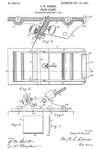
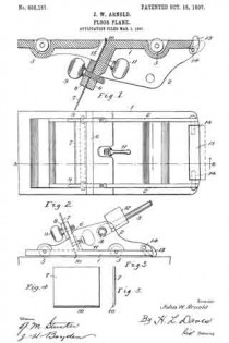
ln the accompanying drawings, forming a part of this specification: Figure 1 is a. longitudinal section. Fig. 2 is a top plan view thereof. Fig. 3 is a side elevation reduced, and Figs. 4 and 5 show the blade in detail.

Similar reference numerals designate corresponding parts in the different figures.

The device comprises a truck of any suitable design mounted upon rollers 5 and having a. base plate 1, and its vertical side walls 2 adapted to receive an operating handle 3 which is journaled thereon by a bolt 4. Said base plate 1 is bifurcated at its rear end as seen in Fig. 2, said bifurcations being adapted to receive therebetween the cam foot 13.

Numeral 6 designates an upright which with the clamping plate 8 and thumb screws 9 constitute the supporting means for the scraper blade 7 which is forwardly inclined as against the usual types which are inclined rearwardly or towards the operating handle. The scraper-blade 7 thus inclined sets its active edge 10 to a drag or relieved position by which all possibilities of its jamming against knots or tearing splinters is obviated. This position rather tends to permit of its readily passing over such obstructions and yet remove therefrom any roughness. The edge 10 of the blade is turned slightly forward, or in the direction of the movement of the scraper, and by means of the regulating screw 11 it may be set to cut at various depths. The opening 15 in the base of the scraper being sufficiently wide to permit this.

To vary the amount of pressure necessary to exert upon the planer as is required on floors of different grains and in the different stages of cleaning a floor, the truck 1, is weighted by one or more weights 12 which are threaded upon the handle.

ln cleaning a floor it is desirable that the scraper-blade should pass over the same only in the necessary operative movements, as any more than that has a dulling and scratching effect on the finish. To remedy this defect my device is provided with a lifting foot or cam 13 suitably journaled to the rear end oi the planer as at 14. Said foot may be operated by gravity, or a spring may be provided to facilitate its movement. In the forward movement of the scraper the cam 13 will remain inactive, that is, — following behind the planer; but upon the reverse movement of the planer the cam immediately engages against the floor and turning upon its bearings 14, raises the rear end of the truck which elevates the edge 10 of the blade 7 sufficiently to permit of its clearing the floor. This operation likewise saves undue wearing on the edge 10 of the blade.

What is claimed as new is:–

1. A floor scraper comprising a truck having a base-plate bifurcated at its rear end, a cam foot pivoted at said end between the bifurcations, a forwardly inclined scraper-blade support located intermediate the ends of the base-plate, a scraper-blade and means for adjustably connecting the same to said support, a roller journaled in rear of the blade, and forward of the cam-foot, another roller journaled in front of the blade, and an operating handle connected to the truck.

2. In a floor scraper the combination of a carriage, an operating handle journaled thereto, removable weights threaded upon said handle, an integral and forwardly inclined upright having a scraper blade secured thereto, the cutting edge of said blade being turned outwardly, means for vertically adjusting said blade, and separate means for adjusting the cutting depth of said outwardly turned edge, and a cam foot journaled to the rear end of the carriage and projecting beyond said carriage, said cam foot adapted to tilt the carriage during its inoperative movement.

In testimony whereof I affix my signature in presence of two witnesses.

JOHN W. ARNOLD.

Witnesses:
W. J. NALLEY,
I. L. HAMMOND.

No. 682,958 – Plane (Thomas M. Seeds, Jr., And Martin Frings) (1901)

[paiddownloads id=”557″]682958


UNITED STATES PATENT OFFICE.

_________________

THOMAS M. SEEDS, JR., AND MARTIN FRINGS,
OF PHILADELPHIA, PENNSYLVANIA.

PLANE.

_________________

SPECIFICATION forming part of Letters Patent No. 682,958, dated September 17, 1901.
Application filed April 12, 1901. Serial No. 55,511. (No model.)

_________________

To all whom it may concern:

Be it known that we, THOMAS M. SEEDS, Jr., and MARTIN FRINGS, citizens of the United States, and residents of Philadelphia, in the county of Philadelphia and State of Pennsylvania, have invented a new and Improved Plane, of which the following is a full, clear, and exact description.

This invention relates to a plane adapted particularly for smoothing floors, but applicable for use in connection with all plane surfaces.

The invention comprises certain peculiar features of construction by which the plane is carried on a wheeled frame and pushed over the floor through the medium of a long handle, thus enabling the operator to stand upright at his work.

This specification is a specific description of one form of the invention, while the claims are definitions of the actual scope thereof.

Reference is to be had to the accompanying drawings, forming a part of this specification, in which similar characters of reference indicate corresponding parts in all the views.

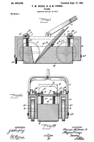
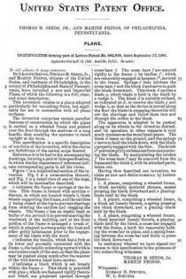
Figure 1 is a longitudinal section of the invention. Fig. 2 is a cross-section thereof; and Fig. 3 is a detail view of one of the dogs, which will be hereinafter described.

a indicates the frame or carriage of the device. This frame is formed with cavities a’
therein, in which are located wheels b, these wheels supporting the frame, andthe cavities a’ being closed at the top to prevent shavings from entering the cavities and clogging the wheels. The frame a has an elastic bead or buffer a2 run around it to prevent marring the woodwork of the building, and at the front portion of the frame is arranged a brush a3, which is adapted to sweep away the dust and other gritty substances prior to the engagement of the blade with the wood.

c indicates the handle, which has a fork at its lower end pivotally connected with the frame a, the handle extending upward within convenient reach of the user, so that the plane may be pushed along much after the manner of the well-known hand lawn-mower.

d indicates a block which is set loosely within the frame a. This block is provided with pins e, which are fastened rigidly thereto and which are projected upward through cross-bars f The cross- bars fare secured rigidly to the frame a by latches f’, which are removably engaged in keepers f2, secured to the frame. Springs e’ bear between the cross-bars f and the block cl and serve to push the block downward. This block cl carries a blade g, which blade is held in the block by a wedge lt. The block d is suitably orificed, as indicated at d’, to receive the blade g and wedge h, so that as the device is moved along the floor the blade in engaging therewith will cut the shavings and throw them into and through the orifice in the block.

The apparatus is adapted to be pushed along on its wheels in the direction desired, and its operation in other respects is very much the same as the usual hand-plane. The block d bears on the ground, and the springs e’ serve to hold the block down, with the blade g properly engaged with the floor. The brush a3 prevents gritty substances from encountering the blade. By manipulating the latches f’ the cross-bars f may be removed from the frame and the block d, with its attached parts, taken out.

Having thus described our invention, we claim as new and desire to secure by Letters Patent —

1. A planer, comprising a wheeled frame, a block movably mounted thereon, means pressing the block downward and a planing-blade held by the block.

2. A planer, comprising a wheeled frame, a block set loosely therein, a spring pressing the block downward, and a planing -blade held by the block.

3. A plane, comprising a wheeled frame, a block mounted loosely therein, a planing-blade held by the block, a cross-bar engaged with the frame, a latch for removably holding the cross-bar in place, and a spring bearing between the cross-bar and block to press the block downward.

In testimony whereof we have signed our names to this specification in the presence of two subscribing witnesses.

THOMAS M. SEEDS, JR.
MARTIN FRINGS.

Witnesses:
NORMAN H. STEVENS,
W. L. STEVENS.

No. 547,829 – Handle Attachment For Planes (John H. Williams) (1895)

[paiddownloads id=”518″]547829


UNITED STATES PATENT OFFICE.

_________________

JOHN H. WILLIAMS, OF TROY, NEW YORK.

HANDLE ATTACHMENT FOR PLANES.

_________________

SPECIFICATION forming part of Letters Patent No. 547,829, dated October 15, 1895.
Application filed July 31, 1893. Renewed May 25, 1895. Serial No. 550,719. (No model.)

_________________

To all whom it may concern:

Be it known that I, JOHN H. WILLIAMS, of the city of Troy, county of Rensselaer, and State of New York, have invented a new and useful Handle Attachment for Planes,of which the following is a specification.

My invention relates to a handle attachment for smoothing-planes to enable the latter to be operated when finishing off hard-wood or other floors without compelling the workman to sit or kneel on the floor. Where hard-wood fioors are finished off with smoothing-planes, the latter are operated by the workman when kneeling or sitting upon the floor, positions producing much discomfort; and the object and purpose of my invention are to have a handle that is attachable to or detachable from the plane, by which when connected with the latter it may be operated by persons standing on their feet.

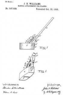
Accompanying this specification, to form a part of it, there is a plate of drawings, containing two figures, illustrating my invention, with the same designation of parts by letter-reference used in both of them.

Of the illustrations, Figure 1 is a side elevation of a smoothing-plane with my handle attachment applied thereto. Fig. 2 is a perspective of the plane and handle attachment with the heel and sole of the plane facing the view.

The several parts of the plane and those containing my invention are designated by letter-reference, and the function of the parts is described as follows:

The letter S designates the stock; B, the bit or iron; W, the wedge holding the iron or bit in the bed b2. The letter T designates the top of the stock, and H its heel, all of which parts are the usual and well-known ones of a smoothing-plane.

The letter I designates the handle- body part, which is made with the handle-socket p2, the heel-piece h2, the bottom b at right angles to the heel-piece, and the upwardly-inclined top A, made with the projecting shoulder h3.

The letter C designates a clamp, which at its upper end tongues into the shoulder h3 and is thereat hinged by means of a hinging-bolt a. This clamp on its inner face is made with a shoulder m and above the latter has its face F parallel to the top A of the handle-body part.

The letter T2 designates a clamping-bolt made to pass downward through the clamp C and the handle-body part below the handle-socket p2, made in the latter, and the lower end of this bolt is threaded and provided with a nut N.

The letter D designates a handle, the lower end of which is adapted to be inserted in the socket p2 for operating the plane.

As thus made, the attachment of handle-body part and plane is made by placing the former with its bottom surface resting on the stock top and its heel-piece bearing against the heel of the stock, with the outer end of the plane iron or bit passing up between the upper part of the clamp and the inclined top A of the body part and with the plane-wedge W between the clamp and the inclined top of the body part below the shoulder h3 of the clamp, with the shoulder resting on said wedge, in which position the bolt T2 is passed down through the clamp and body part and the nut N screwed up onto the lower end of the bolt to bring the clamp and the plane parts, which it and the body part grasp, in close contact and engagement. As thus made, when grasped by the handle the plane may be operated to finish up a floor without the necessity of the workman who uses it getting down onto the floor to move it.

Having thus described my invention, what I claim, and desire to secure by Letters Patent, is —

In a handle attachment for a plane the combination with a body-part made with a heel piece, and constructed with a handle socket and handle; of a clamp hinged to the body-part and adapted to grasp the handle and wedge of the plane and a threaded bolt constructed to secure the parts as connected, substantially in the manner as and for the purposes set forth.

Signed at Troy, New York, this 17th day of September,1892, and in the presence of the two witnesses whose names are hereto written.

JOHN H. WILLIAMS.

Witnesses:
W. E. HAGAN,
CHARLES S. BRINTNALL.

No. 405,540 – Plane (John J. Driver) (1889)

[paiddownloads id=”450″]405540


UNITED STATES PATENT OFFICE.

_________________

JOHN J. DRIVER, OF ST. LOUIS, MISSOURI.

PLANE.

_________________

SPECIFICATION forming part of Letters Patent No. 405,540, dated June 18, 18589.
Application filed December 5, 1888. Serial No. 292,703. (No model.)

_________________

To all whom it may concern:

Be it known that I, JOHN J. DRIVER, a citizen of the United States, residing at St. Louis, in the State of Missouri, have invented certain new and useful Improvements in Planes, of which the following is such a full, clear, and exact description as will enable any one skilled in the art to which it appertains to make and use the same, reference being had to the accompanying drawings, forming part of this specification.

My invention relates to handles for planes, whereby the same can be manipulated by persons when standing to plane floors and the like, obviating the necessity of getting down on the knees.

The invention consists in features and details of construction which will new be set forth at length, and then particularly pointed out in the claims making a part hereof.

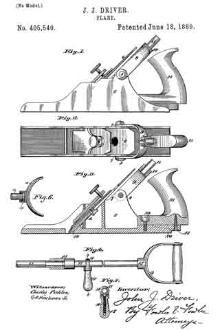
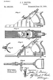
Figure 1 is a side elevation of a plane having my handle applied thereto. Fig. 2 is a plan view of the same. Fig. 3 is a longitudinal sectional view of the same. Fig. 4 is a view showing the handle only. Fig. 5 is a section on the line 5 5 of Fig. 4. Fig. 6 is a section of a detail.

The same figures of reference indicate the same parts throughout the various views.

5 is the plane, whichis of any ordinary construction and preferably made of metal.

6 is the cutter-blade, which is adjusted in said plane by any ordinary means. This means makes no part of my invention. I entend the metal sides of the plane to form ears 7 at each side of said plane, and to these ears 7, I journal my handle by a bolt 8, which passes through said handle and said ears.

The handle is preferably made of a bow-shaped piece 9, which has a screw-threaded socket 10 at its top and middle. This screw-threaded socket receives, preferably, a rod or pipe 11, screw-threaded at both ends, of any desired length, which may be joined to a second piece of pipe 12 to form the handle. The pipes or rods 11 and 12 are joined together by a nut 13, having a right and left hand screw-thread, so that when the nut is screwed down the ends of the rods 11 and 12 are brought together and make a tight joint. To the pipe 12 is swiveled at the point 13′ a handle 14, so that said handle 14 may be turned at any angle. Upon the pipe or rod 12 is also a second handle 15, which is made so as to be adjustable along said rod to accommodate the person using the plane. This handle 15 is made up of a screw-threaded bolt 16, which passes through the wooden part 15 of the handle, and has an eye 18 for receiving the rod 12. By screwing the wooden part 15 in one or the other direction it can be made to approach or recede from the rod 12, and thus allow said handle to be moved along said rod or fastened securely to the same at any point. The handle 14 is for one hand of the user and the handle 15 for the other hand. The ears 7 are about midway between the cutting-line 19 and the heel 20 of the plane, in order that the handle maybe attached to the plane at a point midway between 19 and 20, so as to equalize the pressure at the point 19 and the point 20.

If the handle were attached to the plane farther back, too much pressure would be thrown upon the heel 20 of the plane and too little pressure put upon the cutting-line 19. So, too, if the handle were attached farther forward of the plane too much pressure would be applied along the cutting-line.

The bolt 8 can be readily removed when it is desired to take the handle off of the plane and use it as an ordinary plane. Said handle can be made of any length by joining together any number of sections 11 and 12.

By the means described floors and other objects can be planed by persons when standing as readily as when upon the knees and with much less fatigue.

The invention is simple and effective, the construction strong and of small cost.

21 is the ordinary handle of the plane, which is fastened to said plane by screws 22 and 23, and may be removed from the plane, if in the way, when the other handle is attached.

Having fully set forth my invention, what I desire to claim and secure by Letters Patent of the United States as my invention is —

1. A handle for planes, consisting of the bow-shaped part 9, having screw-threaded socket 10, one or more screw-threaded rods joined to the same, a handle 14, swiveled to the upper end of said rods, and a handle 15, adjustably secured along said rods, for the purpose described.

2. The combination, with a plane, as herein set forth, of the ears 7, a bow-shaped piece 9, swiveled to said ears 7 by a bolt 8, screw-threaded socket 10 upon said bow-shaped piece, screw-threaded rod 11, adapted to be inserted in said socket 10, a second screw-threaded rod 12, a nut 13, having right and left hand screw-threads thereon for joining the rods 11 and 12 together, a handle 14, swiveled to said rod 12, and a handle 15, adjustable along said rod 12, substantially as and for the purpose described.

In testimony whereof I have hereunto set my hand and affixed iny seal, this 3d day of December, 1888, in the presence of the two subscribing witnesses.

JOHN J. DRIVER. [L. S.]

Witnesses:
A. C. FOWLER,
W. S. REEDER.

No. 332,305 – Floor-Plane (Justus A. Traut) (1885)

[paiddownloads id=”402″]332305


UNITED STATES PATENT OFFICE.

_________________

JUSTUS A. TRAUT, OF NEW BRITAIN, CONNECTICUT, ASSIGNOR TO
THE STANLEY RULE AND LEVEL COMPANY, OF SAME PLACE.

FLOOR-PLANE.

_________________

SPECIFICATION forming part of Letters Patent No. 332,305, dated December 15, 1885.
Application filed July 27, 1885. Serial No. 172,773. (No model.)

_________________

To all whom it may concern:

Be it known that I, JUSTUS A. TRAUT, of New Britain, in the county of Hartford and State of Connecticut, have invented certain new and useful Improvements in Floor-Planes, of which the following is a specification.

My invention relates to that class of planes which are provided with along handle for use in smoothing floors; and the objects of my invention are to so hang the long handle that the plane will work smoothly without chattering and to provide a more convenient handle.

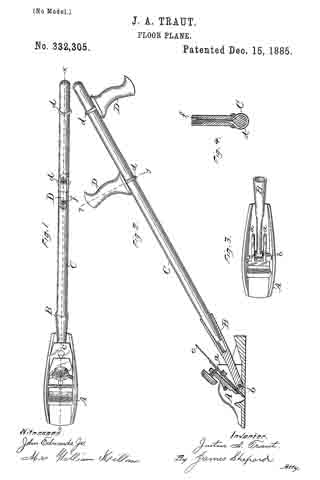
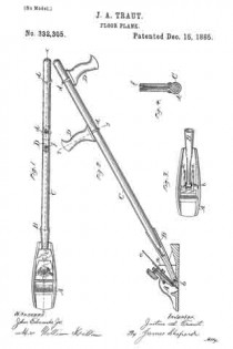
In the accompanying drawings, Figure 1 is a plan view of my plane. Fig. 2 is a vertical section of the plane on the line x x of Fig. 1, with a side elevation of its handle. Fig. 3 is a plan view of said plane with the cutting-bit and holding-cap removed; and Fig. 4 is a sectional view through the handle. on line y y of Fig. 2.

A designates the plane, which in its general features may be of any ordinary construction. The seat for the cutting-bit is formed mainly by the inclined upper surface of the two upright lugs a a. Between these lugs I pivot the socket B for the handle C by means of a bolt, b, which passes through said lugs a a and through an eye at the forward end of the socket B. This pivotal bolt b is located as near the bottom of the stock and as far forward under the cutting-bit c as is practicable, thereby causing the power applied through the handle C and stock B to be transmitted to the stock at such a point relatively to the cutting-edge of the bit as to hold said edge to its work, and thereby cause the plane to work smoothly. I provide the handle C at different points between its ends with two transverse handles, D D, one of which projects upwardly and the other downwardly, which handles are to be grasped by the hands of the operator when shoving the tool over the floor in planing. These handles I attach to the main handle by means of a yoke, d, and nut f, in the manner of attaching transverse handles to scythe-snaths, so that said handles D D may be adjusted to any desired position on the handle C for the convenience of the user.

I am aware that a prior patent shows a floor-plane having rollers at the front end of its stock and a long handle pivoted at the rear end of the stock at a point above the middle of its height, and that another patent shows a floor-plane having a yoke pivoted to its stock at a point about the middle of its height, and about half-way between the cutting-edge of the bit and the rear end of the stock, which yoke is provided with rollers at its lower end, a spring-finger at the top which presses on the forward end of the stock, and a socket which receives a long handle, said handle being provided at its rear end with a single transverse handle or cross arm. All of said prior art is hereby disclaimed.

I claim as my invention —

The herein-described floor-plane, consisting, essentially, of the plane A and the socket B, pivoted to the stock of said plane close to its bottom, underneath the cutting-bit, and just back ofthe cutting-edge of said bit, substantially as described, and for the purpose specified.

JUSTUS A. TRAUT.

Witnesses:
H. S. WALTER,
H. C. HINE.

No. 112,062 – Improvement In Carpenters’ Planes (William Miller) (1871)

[paiddownloads id=”179″]112062


United States Patent Office.


WILLIAM MILLER, OF BOSTON, MASSACHUSETTS, ASSIGNOR TO HIMSELF
AND C. E. WOODMAN, OF SAME PLACE.

Letters Patent No. 112,062, dated February 21, 1871.
_________________

IMPROVEMENT IN CARPENTERS’ PLANES.

_________________

The Schedule referred to in these Letters Patent and making part of the same.

_________________

I, WILLIAM MILLER, of Boston, in the county of Suffolk and State of Massachusetts, have invented certain Improvements in Planes, of which the following is a specification.

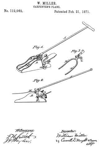
Figure 1 is a perspective view of my invention;
Figure 2 is a side elevation of’ the same; and
Figure 3, a detached view of a modification.

The object of this invention is to enable a carpenter’s plane to be operated at a greater distance from the workmen than the length of his arm, as in planing floors, ceilings, &c.; and It consists of a metallic yoke, pivoted to the plane, and provided with rollers and a projecting finger, and pivoted to a long staff or handle, as will hereinafter more fully appear.

In the drawing —

A represents the plane, on the side of which are the vertical flanges B.
C represents a yoke, which is pivoted to the flanges B by screws D.
The upper portion of yoke C is provided with lugs E and projection F, to the latter of which is attached a spring or finger, H.
The ends of yoke C are provided with rollers, I.
J represents a long handle or staff, which is pivoted at one end to lugs E.

When a forward motion is imparted to the plane A through handle J, the upper portion of yoke C is pushed forward, causing the finger H to bear firmly downward on the forward portion of the plane A, as shown in fig. 1, which places rollers I in such position that their lower edges are flush with the bottom of plane A. The plane is thus caused to operate as effectively as if in the hands of the workman, the finger H holding the foremost end down to its work, which finger, being slightly elastic, does not hold it too firmly.

The plane being drawn backward, the finger H is lifted from the plane, and the rollers I are brought downward until one side of yoke C comes in contact with the projecting pin m, which holds the same in the position shown in fig. 2, the rollers I projecting below the plane A, and slightly raising the same as it is being drawn backward, and protecting the cutting-iron when not in use.

The finger H may be bifurcated, as shown in fig. 3, the bifurcations H’ resting on the flanges B, thereby preventing the shaving from becoming clogged.

Having thus fully described my invention,

What I claim as new, and desire to secure by Letters Patent is —

1. The combination of plane A, yoke C, and rollers I, substantially as described.
2. The combination of plane A, yoke C, rollers I, and single or bifurcated finger H, substantially as described.
3. The combination of plane A, yoke C, rollers I, finger H, and staff or handle J, substantially as described.

In testimony whereof I have signed my name to this specification in the presence of two subscribing witnesses.

WILLIAM MILLER.

Witnesses:
CARROLL D. WRIGHT,
CHARLES F. BROWN.

No. 107,757 – Improvement In Planes (Timothy O. Callahan) (1870)

[paiddownloads id=”151″]107757


United States Patent Office.


TIMOTHY O. CALLAHAN, OF BOSTON, MASSACHUSETTS.

Letters Patent No. 107,757, dated September 27, 1870.
_________________

IMPROVEMENT IN PLANES.

_________________

Specification forming part of Letters Patent No. 107,757, dated December 18, 1870.

The Schedule referred to in these Letters Patent and making part of the same.

_________________

all to whom these presents shall come:

Be it known that I, TIMOTHY O. CALLAHAN, of Boston, in the county of Suffolk and State of Massachusetts, have made an invention of a new and useful Plane for Finishing Board Floors of Halls, Dwellings, Navigable Vessels, &c.; and do hereby declare the following to be a full, clear, and exact description thereof, due reference being had to the accompanying drawing making part of this specification, and in which —

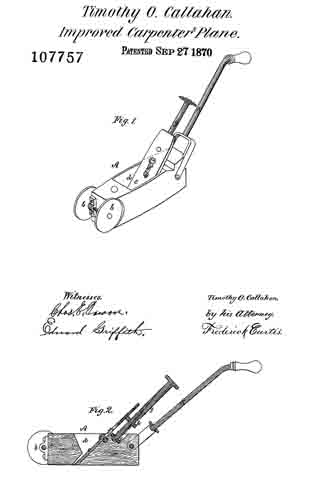
Figure 1 is a perspective view; and
Figure 2, a vertical, central, and longitudinal section of a plane embodying my improvements.

The stooping or crouching position now assumed, of necessity, by carpenters in planing or finishing board floors, and the time consumed in the act, have rendered the introduction of an implement similar to that herein explained of great value, the object to the accomplished being the construction of a plane that may be operated by a carpenter or laborer while in an ordinary erect walking position, the result being great economy of time, as well as lessening of fatigue on the part of the operator.

The invention consists —

First, in mounting a carpenter’s plane upon wheels or rollers, or a carriage supported upon wheels or rollers, in such manner that said plane may be easily propelled over the surface of a floor, while at work; and

Secondly, in providing a carpenter’s plane with an attenuated sloping handle, rising therefrom to such a height as to enable a person to readily grasp it, while in a standing position.

In the drawing which accompanies and constitutes part of this specification —

A represents a carpenter’s plane, the forward end of which is mounted upon wheels or rollers, b b, in order that it may be easily propelled along the floor, the rollers or their equivalents being of considerable weight, in order to insure the contact of the plane with the floor.

The iron of the plane is shown at c as confined within the throat or shaving-passage d of the plane, in part, by a screw, e, which passes through a slot, f formed centrally in the plane-iron, and screws into the rear wall of the throat d, and serves to clamp the iron to the plane.

The vertical adjustment of the plane-iron is effected by a long screw, g, which screws through a stud, h, connected to the rear side of the plane-iron, and at or near the upper part thereof, the lower end of the screw g being swiveled to a metallic plate, i, which is secured to the upper part of the plane, and in rear of its iron, the opposite or upper end of the screw being provided with a milled head, or its equivalent, by which it may be easily rotated.

The plane-iron c is not connected rigidly or immovably to the stud h before mentioned, but merely encompasses the same, consequently, by loosening the screw d, which clamps the iron to the plane, such iron may he instantly removed therefrom, free from any incumberance.

As before observed, the head of the screw g rises to such a position as to be readily seized by a workman while standing erect, or substantially so.

K in the drawing denotes an attenuated handle attached to the rear end of the plane A, and rising therefrom at an oblique angle in parallelism, or there about, with the screw g, which it should slightly overtop, and to such a height as will enable the workman, by its aid, to propel the plane over the surface of a floor in an ordinary walking position, with results and advantages before premised.

l have heretofore stated that the wheels b should possess suflicient gravity to maintain the plane in contact with the floor against irregular movements on the part of the workman, and I would here state that it may, in practice, be found desirable to add a movable weight to the forward end of the plane, in order to facilitate this object.

I would remark, further, that in place of the wheels b the plane may he mounted upon a vehicle or carriage, but I prefer, in practice, to constitute the plane its own vehicle, and the characteristic feature of my invention will be found to consist in providing a plane with a means of support by which the friction between it and the floor is greatly reduced, in addition to its prolonged handle.

As the wheels b or their equivalents are the only points of support or contact necessarily of the plane with respect to the floor, it results that the lower surface of the plane, from its throat rearward, may be sloping or curved, should such form, from any reason, be found necessary.

The merits of a plane provided with a means ol propulsion, as before stated, will be at once apparent to persons whose occupation, like my own, is that of planing floors.

The relief from the strain and unnatural position now, of necessity assumed, and the case and rapidity with which a floor may he planed hy means of my invention need no further comment.

I claim —

A carpenter’s plane, when provided with wheels or rollers and an elongated handle, K, all constructed in the manner and for the purpose herein specified.

TIMOTHY O. CALLAHAN.

Witnesses:
FRED CURTIS,
EDWARD GRIFFITH.

No. 19,539 – Floor Plane (Charles E. Barlow) (1858)

[paiddownloads id=”72″]19539


UNITED STATES PATENT OFFICE.

_________________

CHARLES E. BARLOW, OF PHILADELPHIA, PENNSYLVANIA.

FLOOR-PLANE.

_________________

Specification of Letters Patent No. 19,539, dated March 9, 1858.

_________________

To all whom it may concern:

Be it known that I, CHARLES E. BARLOW, of the city and county of Philadelphia and State of Pennsylvania, have invented a new and useful Improvement in Planes for Planing Decks of Vessels and Boarded Floors; and I do hereby declare that the following is a full and exact description thereof, reference being had to the accompanying drawing, and to the letters of reference marked thereon, making a part of this speciflcation.

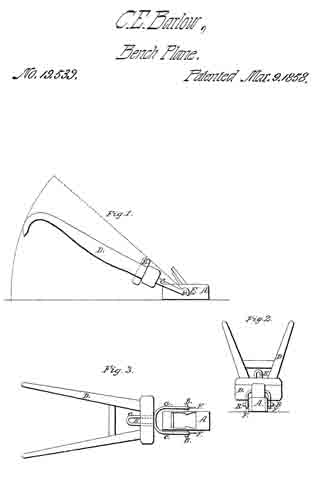
The nature of my invention consists in providing an ordinary carpenter’s plane with a frame, so formed and connected as to enable the operator to stand in the most advantageous position while planing the decks of vessels, boarded floors and other similar surfaces.

Figure 1 is a longitudinal elevation, Fig. 2 is an end view and F ig. 3 is a plan of my improved plane.

A represents a carpenter’s plane of the usual shape having a pivot (B) firmly fixed to each side, said pivots (B) working freely in the bearings formed on the lower part of an iron frame (C). The upper part of the iron frame (C) passes through the lower stay of the wood frame (D) and is secured thereto by a key (E). The upper part of wood frame (D) is formed somewhat like the handles of a plow, the length of which may be made to suit the workman. The total length of the whole (for a man of a medium height) is about five feet. The plane (A) may be detached from the iron frame (C) by withdrawing the pins (E).

When planing off certain kinds of timber I find it advantageous to weight the plane, by attaching a plate of lead to the top of the (A) to slide more steadily over the article being planed but relieves the operator from the necessity of pressing the said plane (A) on to the said article being planed.

The workman when using my improved plane can place himself in any desirable position without moving the plane (A) from the article being planed. That is to say in consequence of the frame (C) being attached to the plane (A) by the pivots B as above stated-the operator may elevate or depress the handles of frames (D) and (C) without affecting the position of the plane A which will therefore in all cases accommodate itself to the work.

The plane A and its connections are worked backward and forward substantially in the same manner as an ordinary plane when being used on a carpenter’s bench; and the decks of vessels, boarded fioors and other similar surfaces can be thereby planed more expeditiously, and with far less manual labor than is required by the usual mode of operation, which is not only tedious and laborious, but painful in consequence of the workman being compelled to rest on his knees while performing the same.

I do not claim broadly the manner of connecting the handle with the stock. But

What I do claim, as a new article of manufacture, is —

The construction of a self adjusting floor plane, with its handle or handles hinged to the stock substantially as described, for the purposes set forth.

CHARLES E. BARLOW.

Witnesses:
JAMES ECCLES,
JOHNN CLOUDS.