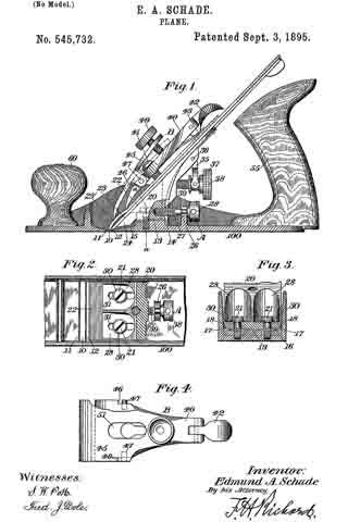
No. 1,021,369 – Plane (Thomas A. Manley) (1912)

[paiddownloads id=”681″]1021369


UNITED STATES PATENT OFFICE.

_________________

THOMAS A. MANLEY, OF AUBURN, NEW YORK, ASSIGNOR TO OHIO TOOL COMPANY, OF AUBURN, NEW YORK, A CORPORATION OF NEW YORK.

PLANE.

_________________

1,021,369. Specification of Letters Patent. Patented Mar. 26, 1912.
Application filed January 18, 1912. Serial No. 671,879.

_________________

To all whom it may concern:

Be it known that I, THOMAS A. MANLEY, a citizen of the United States, residing at Auburn, in the county of Cayuga and State of New York, have invented certain new and useful Improvements in Planes, of which the following is a specification.

This invention relates to improvements in planes, and has for its object to provide novel, simple, convenient and effective means for adjusting the plane-frog longitudinally for facilitating the setting of the bit or plane iron in different positions in the throat of the plane body.

A further object is to provide novel and simple means for locking the frog after the same has been adjusted. And a particular object of the invention is to provide convenient and effective means for adjusting and locking the frog without disturbing the plane iron and related parts.

The various features and parts and the operation of the same, will be fully set forth in the detailed description which follows, illustrated in the accompanying drawing, and then particularly pointed out in the claims.

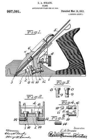
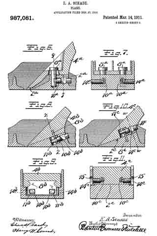
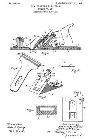
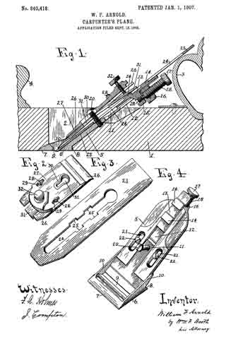
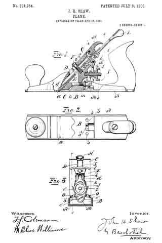
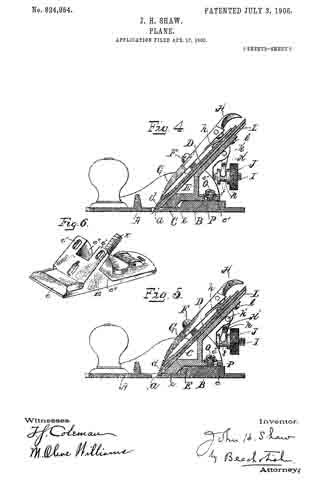
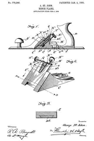
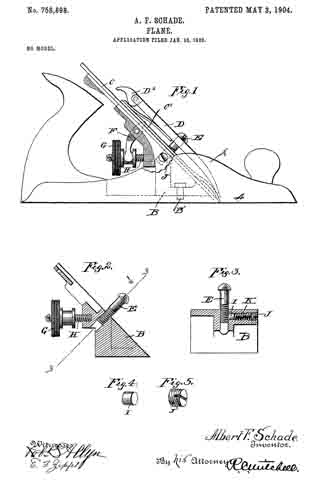
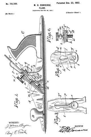
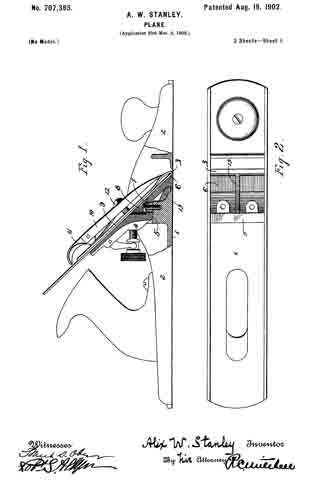
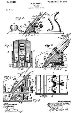
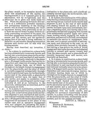
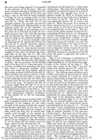
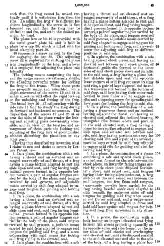
Figure 1 is a side elevation and part section of my complete plane. Fig. 2 is a horizontal section, taken on line 2–2 of Fig. 1. Fig. 3 is a vertical cross-section, taken on line 3–3 of Fig. 2. Fig. 4 is a horizontal section similar to Fig. 2; showing a modification of the locking and adjusting means. Fig. 5 is a vertical cross-section, taken on line 5–5 of Fig. 4.

Similar characters of reference designate like parts throughout the several views.

In the drawing, 2 represents the body of the plane, 3 the sole, 4 the throat or mouth, and 5 the cheeks or lateral guards which are formed integral with the body. The rear side or edge of the throat 4 is formed sharp and thin, and then the metal inclines upwardly and rearwardly at a slight angle for forming a smooth bearing surface 6 which extends across the upper side of the sole 3, to receive a correspondingly formed forwardly projecting portion 7 of the frog 8. The frog 3 consists of an irregularly shaped casting or part having a rearwardly and upwardly inclining top surface 9, for receiving and supporting the plane iron or bit 10, and having a substantially plain horizontal bottom 11, which bears and slides upon a comparatively long elevated step or portion 12, preferably an integral part of the body of the plane. The elevation or seat 12 is disposed a short distance rearwardly of the inclined bearing 6, and its top surface lies in a higher plane than the said bearing. The under side of the frog is correspondingly shaped, so that when the bottom 11 of the frog rests upon the elevation 12, the forward end 7 approaches close to the sloping surface 6. 13 represents like inwardly facing angular ribs or tongues formed horizontally on the cheek pieces 5, directly above the opposite side-edges of the elevated bearing 12, and 14 represents hollow corners or grooves formed in the opposite bottom corners of the frog, the said hollow corners preferably being formed right-angled, so as to clear the ribs 13 when the frog is moved to and fro over the body of the plane. The tongues or ribs 13 are triangular in cross-section, and preferably extend the length of the elevated bearing 12, and they are disposed parallel to said bearing, so that the frog, when operatively connected with the tongues, may be freely moved forward and backward in a true and level plane. The tongues 13 are of sufficient length and strength to effectually hold the frog from chattering while the plane is in operation.

To hold the frog 8 in place on the base 2, and yet allow said part to be freely moved to and fro for adjusting the cutting-blade or bit 10 relatively to the throat 4, the underside of the frog is provided with a broad transverse dove-tail groove or slot 15, in which is operatively fitted a pair of correspondingly shaped keys or locking members 16–17. The keys 16–17 are disposed end to end, in the slot or way 15, and their combined length is slightly less than the breadth of the bearing surface 12 beneath the tongues or guides 13, the outer ends of the keys 16–17 then project beyond each side of the bottom of the frog, as shown in Figs. 2 and 3. The outer ends of the keys 16–17 are beveled to correspond to the under-cut sides of the tongues 13 (see Fig. 3). The abutting ends of the keys 16–17 are provided with transverse concaves 18, the said concaves tapering toward the forward end of the frog.

19 represents a set-screw having a tapering point 19′ extending beyond the threads, the said point being tapered to correspond to the concaves 18 of the keys. The set-screw 19 passes through a threaded hole 20 formed in the rear portion of the frog (see Figs. 1 and 2), the hole 20 being arranged to bring the set or locking screw 19 into coincidence with the abutting ends of the keys 16–17. When the keys 16–17 are brought together, the opposite concaves 18 form a tapering hole corresponding to the tapering point 19′ of the set-screw. In practice, the length of the tapering end of the screw 19 is such that its point 19′ normally projects part way into the tapering hole 18 between the ends of the keys. To lock the frog in any adjusted position the wedge screw 19 is driven inwardly until its tapering end 19′ spreads and forces the keys 16–17 in opposite directions against the beveled under-sides of the tongues or ribs 13 (see Fig. 3). Any desired pressure or tension may be produced by means of the wedging of the screw 19 between the abutting ends of the keys 16–17. The said keys are preferably broad enough to insure a firm bearing beneath and against the tongues 13, and will hold the frog rigidly in place. By the provision of the beveled ends of the keys 16–17, when the screw 19 is driven inwardly for spreading said keys, they exert a downward pressure which forces and holds the frog rigidly against the bearing surfaces of the elevated seat 12. When the keys are made as shown in Figs. 1, 2 and 3, they are not liable to wear seats in the under-side of the ribs 13, which will interfere with the line and accurate adjustment of the frog. In practice the key 16 is made longer than the key 17, so as to bring the abutting ends (18) to one side of the longitudinal center of the body 2. Under this arrangement the screw 19 may be readily manipulated without interference by the handle 21 or the bit adjusting-screw 22.

To assemble the frog and plane body, the frog is inserted between the cheeks 5 just forwardly of the tongues 13, and when brought to the proper position the projecting beveled outer-ends of the keys 16–17 may be entered underneath the tongues 13, after which the frog may be moved rearwardly until brought to the desired position. In constructing the plane body and the frog, the tongues 13 and the hollow-corners 14 are arranged so that the bottom 11 of the frog will rest firmly upon the upper surface of the elevated seat 12.

To adjust the frog to and fro longitudinally, I provide an adjusting screw 25 which enters a threaded hole 26 in the rear side of the frog 8 above the bottom 11. The screw 25 is preferably positioned at one side of the longitudinal center of the plane, so as to facilitate adjusting the frog without interference by the handle 21 or other parts of the plane. The screw 25 is held from longitudinal movement by means of a yoke 27 which forms the upright arm of an L-shaped bracket 28 which is mounted upon the upper side or face of the sole 3, by means of a screw or pin 29. The screw 25 has a circumferential groove 25′ to receive the yoke 27. When the screw 25 is turned in either direction by hand or by means of a screw-driver, it will move the frog to and fro longitudinally on the base 2. The provision of the guide tongues 13 and the corresponding beveled keys 16–17 will prevent vertical movement of the frog, as well as, lateral and longitudinal rocking of said part relative to the base, and this arrangement also insures the smooth, free and true horizontal movement of the frog on the elevated bearing surface 12. The provision and arrangement of the tongues 13 and the locking keys or members 16–17 will also effectually obviate the chattering of the bit when the plane is operated over hard or burly wood.

Figs. 4 and 5 illustrate a modification of the adjusting and locking parts, and also a slight modification of the form and arrangement of the bottom of the frog 8′. The lower side corners of the frog 8′ are provided with annular grooves 14′, which conform to the shape of the tongues 13′ (see Fig. 5). The locking means comprise apair of like round keys or pins 30 and 31 which are loosely disposed in a hole 32 which passes transversely through the lower portion of the frog. The outer ends of the pins or keys 30 and 31 are beveled to correspond to the under-out sides of the guide ribs 13′, and their combined length is slightly less than the distance between the ribs 13′, for permitting endwise adjustment, the same as the keys 16–17. The keys 30 and 31 are preferably the same length, and their inner ends meet at the transverse center o-f the frog. The abutting ends 33 of the keys 30–31 are formed concave, and taper forwardly, similar to the construction shown and described for the keys 16–17. To lock the frog 8′ from longitudinal movement, I provide a screw 34 which enters a threaded hole 35 formed centrally in the rear-part of the frog 8′. The inner end of the screw 34 is provided with a tapering point 36, which is arranged to enter the tapering concaves arranged in the abutting ends of the keys 30 and 31 for wedging them apart. When the screw 34 is driven inwardly the point 36 spreads the keys 30–31 and forces said keys laterally for tightly engaging the underside of the ribs 13′. When the screw 34 is driven tightly between the keys, the frog 8′ will be held from longitudinal movement. The arrangement of the dove-tail tongues 13′ and the similar grooves 14′ is such that, the frog cannot be moved vertically until it is withdrawn free from the ribs. To adjust the frog 8′ to different positions longitudinally, the screw 34 is first loosened up, and then the frog may be shifted to and fro, and set in the desired position, by hand.

The plane iron or bit 10 is provided with the usual guard plate 37, and is held in place by a cap 38, which is fitted with the usual clamping part 39.

40 represents a screw carried by the frog for engaging the cap 38. The adjusting screw 22 is employed for shifting the plane iron longitudinally on the frog, and a lever 41 is employed for adjusting the plane iron laterally.

The locking means comprising the keys and the wedge screws are extremely simple, yet affording powerful means for locking the frog to the frame. When these parts are properly made and assembled, but a slight movement of the screws 19 and 34 in either direction will effect the rigid locking or the unlocking and freeing of the frog. The broad keys 16–17 cooperating with the side ribs 13 tend to steady the frog during its forward and backward movements. The disposition of the screws 19 and 25 at or near the sides of the plane render the locking and adjusting parts conveniently accessible, and in view of the location and arrangement of these parts the locking and adjusting of the frog may be accomplished without disturbing the plane-iron or any other part.

Having thus described my invention what I claim as new and desire to secure by Letters Patent, is —

1. In a plane, the combination with a sole having a throat and an elevated seat arranged rearwardly of said throat, of a frog having a plane bottom adapted to rest and slide upon said seat, said frog having longitudinal grooves formed in its opposite bottom corners, a pair of angular tongues carried by the body of the plane, said tongues received by said grooves, and adjustable means carried by said frog adapted to engage said tongues for guiding and locking said frog.

2. In a plane, the combination with a sole having a throat and an elevated seat arranged rearwardly of said throat, of a frog having a plane bottom adapted to rest and slide upon said seat, said frog having longitudinal grooves formed in its opposite bottom corners, a pair of angular tongues carried by the body of the plane, said tongues received by said grooves, adjustable means carried by said frog adapted to engage said tongues for guiding said frog, and a screw cooperating with said means for locking said frog rigidly to the elevated seat.

3. In a plane, the combination with a sole having a throat and an elevated seat arranged rearwardly of said throat, of a frog having a plane bottom adapted to rest an slide upon said seat, said frog having longitudinal grooves formed in its opposite bottom corners, a pair of angular tongues carried by the body of the plane, said tongues received by said grooves, adjustable means carried by said frog adapted to engage said tongues for guiding and locking said frog, and a swivel-screw for adjusting said frog to different positions on said sole.

4. In a plane, the combination with a sole having spaced cheek pieces and having an elevated seat between said cheek pieces, of horizontal guide-ribs formed on the inner sides of said cheek pieces above and parallel to the said seat, a frog having a plane bottom slidable upon said seat, the opposite lower corners of said frog cut away to clear said ribs, a pair of keys disposed end to end in a transverse slot formed in the bottom of said frog, said keys having their outer ends beveled to pass under and to engage said ribs, and a tapering screw for spreading said keys apart for locking the frog to said ribs.

5. In a plane, the combination of a sole having a transverse throat and an inclined bearing adjacent the throat, and having an elevated seat adjacent the inclined bearing, triangular ribs formed above and parallel to the said elevated seat, a frog having a plane bottom surface adapted to engage and slide upon said elevated seat between said ribs, said frog having portions out-away for clearing said ribs, and a pair of transversely movable keys carried by said frog adapted to engage said ribs for guiding and also for locking said frog.

6. In a plane, the combination of a frame comprising a sole and spaced cheek pieces, a raised seat formed on the sole between the cheek pieces, an inwardly facing tongue carried by each cheek piece disposed horizontally above said raised seat, said tongues having their facing sides under-cut, a frog slidable on the said raised seat between the said tongues, but free from said tongues, transversely movable keys carried by the frog having beveled outer ends adapted to slide beneath the under-out sides of said tongues for guiding said frog when moved to and fro on said seat, and a wedge-screw carried by said frog adapted to force and hold said keys against said tongues for locking said frog from movement in any direction.

7. In a plane, the combination with a body having an integral elevated seat lying between like cheeks projecting upwardly on its opposite sides, and ribs formed on the inner sides of said cheeks and overhanging said elevated seat, said ribs disposed parallel to the said elevated seat and also to the sole of the body, of a frog having a plane bottom surface adapted to engage and slide upon the said elevated seat, said frog having its opposite bottom corners. cut-away to receive said ribs, and means carried by said frog adapted to engage said ribs for holding said frog from vertical movement.

8. In a plane, the combination of a frame comprising a sole and spaced cheek pieces, a raised seat formed on the sole between the cheek pieces, an inwardly facing; tongue carried by each cheek piece disposed horizontally above said raised seat, said tongues having their facing sides under-cut, a frog slidable on the said raised seat between the said tongues, but free from said tongues, transversely movable keys carried by the frog adapted to slide beneath the under-cut sides of said tongues for guiding said frog when moved to and fro on said seat, a wedge-screw carried by said frog adapted to force and hold said keys against said tongues for locking said frog from movement in any direction, and a swivel-screw for adjusting said frog to different positions in the said frame.

9. In a plane, the combination with a body having an integral elevated seat, said body having like cheeks projecting upwardly on its opposite sides, and ribs formed on the inner sides of said cheeks and overhanging said elevated seat, said ribs disposed parallel to the said elevated seat and also to the sole of the body, of a frog having a plane bottom surface adapted to engage and slide upon the said elevated seat, said frog having its opposite bottom corners cut-away to receive said ribs, means carried by said frog adapted to engage said ribs for guiding said frog during its longitudinal movements, and means for adjusting said frog to different positions on said elevated seat.

10. In a plane, the combination of a body having vertically disposed lateral guards, ribs carried by the inner faces of said guards, said ribs arranged parallel to the sole of said body, an elevated step disposed beneath and parallel to said ribs, a frog having a substantially flat bottom adapted to rest and slide upon said elevated step, the opposite sides of said frog cut-away to clear said ribs, transversely disposed keys carried by said frog, the outer ends of said keys projecting beyond said frog adapted to engage the under-cut edges of said keys for holding said frog firmly upon said step, said keys and said ribs cooperating for guiding said frog when moved to and fro on said body, and a wedge-screw carried by said frog adapted for spreading said keys for rigidly locking said frog to the said ribs.

11. In a plane, the combination of a sole having a transverse throat and an inclined bearing adjacent the throat, and having an elevated seat adjacent the inclined bearing, triangular ribs disposed above and parallel to the said seat, a frog having a plane bottom surface adapted to engage and slide upon said seat between said ribs, a pair of keys carried by said frog adapted to engage said ribs for guiding and also for locking said frog, and a screw for adjusting said frog to different positions relative to said throat.

In testimony whereof I affix my signature in presence of two witnesses.

THOMAS A. MANLEY.

Witnesses:
G. W. BAYNON,
N. L. CASEY.

_________________

Copies of this patent may be obtained for five cents each, by addressing the “Commissioner of Patents, Washington, D. C.”
_________________

No. 987,081 – Plane (Edmund A. Schade) (1911)

[paiddownloads id=”678″]987081


UNITED STATES PATENT OFFICE.

_________________

EDMUND A. SCHADE, OF NEW BRITAIN, CONNECTICUT, ASSIGNOR TO THE STANLEY RULE & LEVEL COMPANY, OF NEW BRITAIN, CONNECTICUT, A CORPORATION OF CONNECTICUT.

PLANE.

_________________

987,081. Specification of Letters Patent. Patented Mar. 14, 1911.
Application filed December 27, 1910. Serial No. 599,481.

_________________

To all whom it may concern:

Be it known that I, EDMUND A. SCHADE, a citizen of the United States, residing at New Britain, county of Hartford, State of Connecticut, have invented certain new and useful Improvements in Planes, of which the following is a full, clear, and exact description.

My invention relates to an improved frog adjustment for a bench plane, whereby the frog, which is the means for supporting the plane iron, may be readily adjusted to and fro, and which, when locked in position, is rigidly held in such a manner as to reduce to a minimum any chance of slippage or displacement.

In the drawings, Figure 1 is a longitudinal section of a plane showing my improved adjustment. Fig. 2 is a section on the plane of the line x–x, Fig. 1, looking from left to right. Figs. 3, 4 and 5 are detail views. Fig. 6 is a longitudinal section of part of a plane of slightly modified construction from that shown in Fig. 1, my invention being applied thereto. Fig. 7 is a cross section on the line y–y of Fig. 6, looking from right to left. Fig. 8 is a longitudinal section of a part of a plane of another modified form. Fig. 9 is a cross section on the line z–z Fig. 8, looking from left to right. Fig. 10 is a longitudinal section illustrating still another modification. Fig. 11 is a cross section thereof on the line w–w looking from right to left.

Referring to Figs. 1 to 5, 1 represents a sole of an iron bench-plane which may be, as to general details, of conventional form. 2 is a frog bearing, in this particular instance formed on an incline directly to the rear of the throat 3. 4 is a frog adjustably mounted on the support 2 for movement to and fro relatively to the throat 3. 5 is a plane iron. 6 is a cap of conventional form and by which the plane iron may be clamped to the frog 4. The invention in this case resides primarily in the means for adjustably securing the frog 4 to the frog support 2. In this instance the frog is provided with two longitudinal slots or passages 7 in which stand clamping or gripping studs 8–8. These studs are headed, the headed portions standing above the slots, the opposite ends projecting down into cavities or recesses in the support 2. Each stud is transversely recessed toward its lower end, as indicated at 9. 10 is what I will term a cam stud, there being one for each gripping stud 8. The cam studs are arranged in the support 2, suitable bores being provided therefor, the rear ends of said studs being arranged to receive a suitable tool, for example, a screw driver, the forward end of each cam stud being provided with an eccentric projection or cam 11. This cam 11 projects into the recess 9 of the respective gripping stud. 12 is a slot in the side of each cam stud. Entering from the side of the plane is a locking screw 14, the same being so arranged relatively to the slotted portion 11 of the cam stud that the forward ends of each screw 14 will engage the wall at the base of the recess 12 at one side of, or eccentric to, the axis of the cam stud.

In the operation of the parts thus far described, it will be seen that by rotating the cam stud in the proper direction, the cam 11 will engage with the wall at the lower end of the recess 9 in the gripping stud so that said gripping stud will be pulled down into firm gripping engagement with the frog 4. To give a further set to the cam and to guarantee against disengagement, the screw 14 may be turned in until its nose engages eccentrically said cam stud, tending to turn it in a direction to increase the tension of the cam on the gripping stud and also preventing any rotation of the cam stud in a reverse direction to release said gripping stud. I have found, by this means, that the frog may be very quickly and easily adjusted, and, at the same time, when locked in position, is held with exceeding rigidity.

In the other views I have shown slight modifications. For example, in Figs. 6 and 7 I have shown the frog 4a as mounted upon a support 2a having a two-point bearing for the frog. In this case as before, the frog is held by means of gripping studs 8a operated by cam studs 10a which are in turn controlled by screws 14a.

In Figs. 8 and 9 I have shown a modification in which instead of providing the gripping studs 8 for holding the frog to its seat, I have provided the frog 4b with a plate-like extension 8b which is preferably cast into the frog, so as to be a permanent part thereof, said plate 8b having passages to receve the cam ends 11b of the cam studs 10b. In this case, as previously, the side screws 14b may be employed to cooperate with the cam studs for the same purpose as before.

In Figs. 10 and 11 I have shown a modification more particularly of the construction shown in Fig. 8 in that instead of anchoring the aforesaid plate in the frog, I have anchored a similar plate in the frog support. In these views, 8c represents said plate anchored in the support 2c, and in this case the cam studs 10c are carried in passages in the rear of the frog 4c, the cam ends 11c engaging the walls of the slot in the plate 8c in the same manner as the cam ends 11b engage the walls of the slot in the plate 8b, shown in Figs. 8 and 9. Here again take-up screws are employed, the same being indicated at 14c. In this case the take-up screws are carried by threaded bores in the sides of the frog, suitable windows or clearance openings 15 being provided in the cheek pieces of the plane to permit a screw driver to be entered sufficiently to engage the slotted ends of said screws 14c for the purpose of operating the same.

In both forms of devices shown in Figs. 8 to 11, a suitable clearance space is provided for the plates 8b and 8c respectively whereby there may be a relative movement between said plate and the part carrying the cam screw. In these cases, the cam ends 11b and 11c respectively should be of sufficient length to engage the plates 8b and 8c respectively in all of the various positions of adjustment.

What I claim is:

1. In a plane, a main body portion having a throat therein, a frog support at the rear of said throat, a frog adjustable to and fro thereon, a locking means for holding said frog in different positions of adjustment comprising a clamping member operatively engaged with one of said parts, means for operating said clamping member carried by the other part and comprising a rearwardly projecting cam stud coacting with said clamping member, and a lock and tightener for said cam stud, said lock and tightener comprising a laterally projecting exposed screw engaging said cam stud in a direction to turn the same as said lock and tightener is advanced.

2. In a plane, a main body portion having a throat therein, a frog support at the rear of said throat, a frog adjustable to and fro thereon, a locking means for holding said frog in different positions of adjustment comprising a clamping member operatively engaged with one of said parts, means for operating said clamping member carried by the other part and comprising a rearwardly projecting cam stud coacting with said clamping member, a lock for said cam stud, said lock comprising a laterally projecting exposed screw, and a shoulder on one side of said cam stud eccentric thereto, said screw engaging said eccentric shoulder and pressing against the same in a direction to turn said cam stud so as to more tightly engage the clamping member.

3. In a plane, a body portion having a throat, a frog support at the rear of said throat, a frog adjustable to and fro on said support and relatively to said throat, a clamping member carried by said frog and projecting into said support, said support having a recess therefor, a cam stud carried in said support and exposed at its rear end, an eccentric pin extension at the forward end of said stud eccentrically engaging said clamping member, and a lock screw for engaging said clamping stud at one side and arranged laterally thereto.

4. In a plane, a body portion having a throat, a frog support at the rear of the throat, a frog mounted for adjustment to and fro on said support, said frog having a fore and aft slot therein, a clamping stud passing downwardly through said slot into said support, an operating device for said clamping stud comprising a cam stud mounted in said support, an eccentric pin projection at the forward end of said cam stud eccentrically engaged with said clamping stud, and a lock for said cam stud.

5. In a plane, a body portion having a throat, a frog support at the rear of the throat, a frog mounted for adjustment to and fro on said support, said frog having a fore and aft slot therein, a clamping stud passing downwardly through said slot into said support, an operating device for said clamping stud comprising a cam stud mounted in said support, an eccentric pin projection at the forward end of said cam stud eccentrically engaged with said clamping stud, and a lock for said cam stud, said lock comprising a screw entering said frog support from the side of the plane.

6. In a plane, a body portion having a throat, a frog support at the rear of the throat, a frog mounted for adjustment to and fro on said support, said frog having a fore and aft slot therein, a clamping stud passing downwardly through said slot into said support, an operating device for said clamping stud comprising a cam stud mounted in said support and eccentrically engaged with said clamping stud, and a lock for said cam stud, said lock comprising a screw entering said frog support from the side of the plane, said screw engaging said cam stud eccentrically to rotate the same in a direction to increase the pressure on the clamping stud.

EDMUND A. SCHADE.

Witnesses:
W. J. WORAM,
H. S. WALTER.

_________________

Copies of this patent may be obtained for five cents each, by addressing the “Commissioner of Patents, Washington, D. C.”
_________________

No. 930,307 – Plane (Charles E. Mitchell And Edmund A. Schade) (1909)

[paiddownloads id=”664″]930307


UNITED STATES PATENT OFFICE.

_________________

CHARLES E. MITCHELL, OF NEW YORK, N. Y., AND EDMUND A. SCHADE, OF NEW BRITAIN, CONNECTICUT, ASSIGNORS TO THE STANLEY RULE & LEVEL COMPANY, OF NEW BRITAIN, CONNECTICUT, A CORPORATION OF CONNECTICUT.

PLANE.

_________________

930,307. Specification of Letters Patent. Patented Aug. 3, 1909.
Application filed May 6, 1902. Serial No. 106,200.

_________________

To all whom it may concern:

Be it known that we, CHARLES E. MICHELL and EDMUND A. SCHADE, citizens of the United States, residing at New York, N. Y., and New Britain, Connecticut, respectively, have invented certain new and useful Improvements in Planes, of which the following is a full, clear, and exact description.

Our invention relates to improvements in the construction of planes, and particularly to the parts which are adapted to carry and provide adjustment for plane irons in that class known as bench planes.

The part of the plane which immediately supports the cutting tool or plane iron is commonly termed a frog. This part is so constructed as to bear upon and be supported by the stock portion of the plane and to itself carry and provide means for adjusting the position of the iron. This frog is commonly constructed of cast iron and separate from the base or stock portion of the plane. Frogs constructed in this manner of cast metal are heavy, and having the usual characteristics of such metal, are easily broken and but poorly adapted to withstand the strains to which such a structure is subjected. The great weight is also a material element in considering the usefulness and general utility of a plane. For this reason, it is desirable that the parts shall he made as light as possible and consistent with a requisite strength. In casting such a body as this, it is not feasible to make it of such a finish as to be immediately useful in the final construction which is desired. For this reason it is necessary that it should be put through several finishing operations under machine tools in which the surfaces are given the proper angles relatively to one another and finished to present satisfactory bearing surfaces and appearance. Being of irregular and peculiar shape, there are moreover set up in a frog strains due to the unequal cooling of the metal in different parts of the frog consequent upon the casting operation. These strains are likely to and often do cause checks and irregularities in the structure to such a degree that the parts are the more easily subject to fracture when used in the ordinary course of business. Even if actual defects do not appear on the surface of the metal, there sometimes are such initial strains in the interior as to seriously impair the strength of the parts. For these reasons and in order to make the structure in a more simple and economical manner we have constructed the parts of sheet metal which may he for instance cold rolled steel. ln this way a very light, reliable and economical structure is effected which in its use is most satisfactory and durable.

ln the drawings: Figure 1 is a side elevation partly in section of a plane embodying the improvements of our invention. 2 is a perspective view from the rear of the parts which immediately support a plane iron. Fig. 3 is a rear elevation of the same with what may be termed yoke portion of Fig. 4. Fig. 4 is a perspective view from the front of this so-called yoke portion. Fig. 5 is a view partly in section of the Y-adjustment lever which is used with the part of Fig. 2. Fig. 6 is a side elevation and section of the plane iron supporting member and adjusting devices.

In Fig. I the stock or base portion of the plane is represented as shown at 1 which may have as usual a rear handle and a forward knob for convenience in handling the same. In the base of the stock portion is provided the usual throat or opening 10, and to the rear a chair or seat 13. Above the chair is supported the part 2 which may he herein termed the frog and which provides the immiediate support or bearing for a plane iron. Beneath this frog is what may be conveniently termed a yoke portion 3 which may he attached to the frog as hereinafter set forth. The plane iron 4 which rests upon the face of the frog is in the form shown provided with a plate 5 at its upper surface. These are in turn held in place by a cap iron 6 and are provided with the Y-adjustment lever 7 coacting with an adjusting nut 8. A laterally adjusting lever 9 is secured at the top of the frog.

The yoke portion 3 which is formed at the lease in a manner suitable to cooperate with the chair portion 13 of the stock 1, is provided with slots or holes 30. Through these holes pass the screws 31 which secure the yoke portion to the base and thus provide a forward and backward adjustment for the position of the frog. The front end 32 of the base portion of the yoke may be bent downward at an angle to correspond with the under surface of the face of the frog to which it may be secured, as for example by rivets. The upright portion or back of the yoke extends upward and is secured at the downwardly bent portion 36 to the frog at a point just above the opening 20 in the face of the frog. Through this opening access may be had readily to the securing screws 31 in the base.

When the plane iron and plate are adjusted in position and secured to the frog by means of the cap iron 6 and cap screw 61, the frog is subjected to stresses of considerable amounts. To provide for meeting these stresses it is desirable that the sides of the frog should be bent down and depressed to form reinforcing flanges. It will be noted that these flanges as shown are substantially triangular in form and correspond in depth from the face of the frog very closely to the diagram of changes in bending moments which would occur in a beam loaded in the center and supported at the ends, which is the case that we have herein. The cap iron 6 is provided with a cam lever 65 for effecting the requisite pressure between the cap and the plane iron or the plane iron plate for holding the parts in place.

The upper end of the bearing face of the frog is depressed in a truss-like form at 29 to provide a recess in which the lower end of the aterally adjusting lever 9 may be pivoted at 92 and operate. The end of this lever 9 may be provided as is usual in planes of this character with a disk 94 which cooperates with a slot 40 in the plane iron 4 to effect the desired lateral adjustment. The depth of the cutting edge of the instrument may be adjusted by means of what is known as a Y-adjustment 7 in which the nose 75 projects forward through an opening in the face of the frog into a hole 50 in the plate which is above the plane iron. The plane-iron and plate being secured together by the screw 45, movement up and down of the Y-adjustment will also operate the plane iron itself.

The face of the frog is provided with a perforation or recess to receive the head of the securing screw which is thus let into the platform and allows the plane iron to have a smooth and even bearing upon the face of the frog. Above this recess the metal of the frog may be cut out and bent back in the form of ears 27 which will provide bearings for the pivot of the Y-adjustment. In order that these ears may be bent back at convenient angles and with as little injury to the metal as possible, it is desirable that the sides of the recess should be cut back both above and below the ears and at the base thereof as shown particularly in Fig. 3. ln order that the Y adjustment 7 may have a secure and even bearing and also to increase the economy and efficiency of the device, we have made the Y-adjusting lever 7 of sheet metal as shown in Fig. 5, in which 70, 70 are perforations in the two opposite sides of the lever to provide for the pivot pin. It will thus be seen that the lever has two bearings and that they are spaced apart a considerable distance. The lower ends of the arms 78 coact with the adjusting nut 8 which operates on the screw 81. in this construction as shown particularly in Fig. 6 the adjusting screw 81 is conveniently seated in the back of the yoke at a point near the top thereof where the strength and rigidity of the same would be sufficient to give it a secure bearing. lt is also desirable that the face of the frog should have a reinforcing piece at the point where the cap screw 61 is attached thereto. The bent down portion 36 of the yoke provides this in a most satisfactory manner. By this structure also the cap screw tends to aid in holding the yoke and the frog more securely together. The upper portion 33 of the back of the yoke may be out away as appears most clearly in Fig. 3, and thus provide an easy and convenient access for the purpose if desired of riveting the plate 36 to the frog 2. The lower front end of the yoke acts also as a reinforcement to the lower front edge or toe of the frog in the structure herein shown, and materially adds to the strength and efficiency of the parts since the pressure of the lower end of the cap iron 6 is applied near this point. The cutting edge of the plane iron may be projected through the throat or slot 10 in the base of the stock portion just in front of the toe of the frog. The face of the frog is also reinforced as shown by the depressed portion 29 which in stamping the article forms a corrugation at that point substantially opposite the point of application of the pressure applied by the cam lever 65 at the upper end of the cap iron.

The whole structure is exceedingly light in weight and although very simple and economical in its construction is durable and efficient.

The yoke 3 forms a backing for the plane-iron and may be referred to in some of the claims by the term backing or frog backing.

What we claim is:

1. In a plane the combination of a stock-portion having a throat therein for the passage of a plane-iron, a chair at the rear of said throat, a sheet metal frog adapted to sit upon said chair, a plane-iron bearing against the face of said frog, a plate for said plane-iron, a screw for securing said plane-iron and said plate together, a perforation through the face of said frog forming a cavity to receive the head of said screw the head of said screw being accessible from the rear of said frog, the sides of said frog being depressed to form supporting flanges, substantially as described.

2. In a plane the combination of a stock-portion having a throat therein for the passage of a plane-iron, a chair at the rear of said throat, a sheet metal frog sitting upon said chair, a plane-iron bearing against the face of said frog, a plate reinforcing said plane-iron, a screw for securing said plane-iron and said plate together, a recess in the face of said frog forming a cavity to receive the head of said screw, pivot ears formed from the metal of the face of said frog and bent above said recess forming bearings for the pivot of an adjustment lever.

3. In a plane the combination of a stock-portion having a throat therein for the passage of a plane-iron, a chair at the rear of said throat, a sheet metal frog sitting upon said chair, a plane-iron bearing against the face of said frog, a plate for said plane-iron, a screw for securing said plane-iron and said plate together, a perforation through the face of said frog forniing a cavity to receive the head of said screw, pivot ears formed frori the metal of said frog and above said cavity forming bearings for the pivot of an adjustment lever, said adjustinent lever being formed of sheet metal and having bearings in the opposite sides thereof, substantially as described.

4. In a plane the combination of a stock-portion having a throat therein for the passage of a plane-iron, a raised chair at the rear of said throat, a sheet metal frog for said chair, a plane-iron bearing against the face of said frog, a plate over said plane-iron, a screw for securing said plane-iron and said plate together, a perforation through the face of said frog forming a cavity to receive the head of said screw the head of said screw being accessible from the rear of said frog, the sides of said frog being depressed and forrning triangular shaped supporting flanges for said frog resting on said chair, the forward edge of said frog projecting downward beyond the chair and resting on the sole back of the throat and forward of the chair.

5. In a plane, a stock-portion having a chair seat therein, a frog adapted to support a plane-iron and adjacent parts, the sides of said frog being depressed to form supporting and reinforcing flanges and a sheet metal yoke portion secured to said frog, and means for securing said yoke portion to said frog portion, substantially as described.

6. In a plane, the combination of a stock-portion, a frog for supporting a plane-iron, the said frog being formed of sheet metal having the opposite sides depressed to forrn supporting and reinforcing flanges, a yoke secured to said frog forming a seat for said frog, and a screw secured in said yoke portion and adapted to carry a means for adjusting the cutting depth of a plane-iron.

7. In a plane, a stock-portion having a chair therein, a sheet metal frog adapted to support a plane-iron, screws for securing said frog to said stock-portion, a perforation through the face of said frog to permit of access to the said screws, a plane-iron having a plate at the top thereof, a screw for securing said plate and said iron together, a perforation in the face of said frog to receive the head of said screw, a lever for laterally adjusting the position of said plane-iron, a depressed portion from the face of said frog to form a recess to receive said laterally adjusting lever, pivot ears struck from the metal of said frog and bent down to form bearings for an adjustment lever, the metal of the face of said frog being cut away above and below at the sides of said ears, substantially as described.

8. ln a plane, a stock-portion having a chair therein, a sheet metal frog adapted to support a plane-iron, screws for securing said frog to said stock-portion, a perforation through the face of said frog to permit of access to said screws, a plane-iron having a plate at the top thereof, a screw for securing said plate and said iron together, a perforation in the face of said frog to receive the head of said screw, a lever for laterally adjusting the position of said plane-iron, a depressed portion from the face of said frog to form a recess to receive said laterally adjusting lever, pivot ears struck from the metal of said frog and bent down to forrn bearings for an adiustrnent lever, the metal of the face of said frog being out away at the sides of said ears, and a yoke portion secured to said frog forming a reinforce therefor, and providing a bearing for a cap screw and also a bearing for an adjusting screw.

9. ln a plane, a sheet metal frog forrned with depressed side flanges, a sheet metal yoke having slots in the base thereof for adjusting-screws, said yoke being bent down at the upper portion and secured to the underside of the face of said frog, substantially as described.

10. ln a plane, a sheet metal frog formed with depressed side flanges, a sheet metal yoke having slots in the base thereof for adjusting-screws, said yoke being bent down at the upper-portion and secured to said frog, and a cut out portion in the face of said frog below the point of attachrnent of the upper end of said yoke, whereby access may be had to the slots in the base of said yoke, as and for the purpose specified.

11. In a plane, a frog formed of sheet metal having the sides depressed to form supporting flanges , a yoke formed of sheet metal and separately therefrom but united to the underside of the face thereof at the lower end and also at the upper end by a bent down portion, substantially as described.

12. ln a plane, a stock-portion, a frog for and forming a bearing for a plane-iron, means for securing said frog to said stock-portion, a plane-iron secured to the face of said frog, a plate secured to said plane-iron, a screw for fastening said plate to said iron, a recess in the face of said frog forming a cavity to receive the head of said screw, bearings formed integral with said frog and above said recess, an adjustment lever formed of sheet metal and having its nose projecting upward into a hole in said plate and having bearings in the two opposite sides thereof for a pivot therefor, and means for operating said adjusting lever, substantially as described.

13. In a plane, a stock-portion, a frog for and forming a bearing for a plane-iron, means for securing said frog to said stock-portion, a plane-iron secured to the face of said frog, a plate secured to said plane-iron, a screw for fastening said plate to said iron, a recess in the face of said frog forming a cavity to receive the head of said screw, pivot bearing ears formed integral with said frog, the face of said frog being out away at the sides near the upper and lower edges of each pivot bearing ears for the purpose specified.

14. In a plane, a stock-portion, a frog for supporting a plane-iron, a yoke portion formed of sheet metal and secured to said frog portion and having slots in the base thereof for receiving securing screws and a support in the rear thereof for carrying a Y-adjustment screw.

15. In a plane, a frog formed of sheet metal having a perforation near the top thereof to receive a screw-head, a yoke portion formed of sheet metal and at its lower forward edge parallel to the face of said frog portion, the base of said yoke portion being bent back from the face of said frog to form a bearing surface and slotted to receive securing screws, the back of said yoke portion being adapted to form a bearing for an adjustment lever screw, and means for securing the upper end of said yoke to said frog.

16. In a plane, a frog formed of sheet metal having a recess near the top thereof to receive a screw-head, a yoke portion formed of sheet metal and secured at its lower forward edge to said frog portion, the base of said yoke portion being bent back from said frog and having holes to receive securing screws, the back of said yoke portion being adapted to form a bearing for an adjustment screw, the upper end of said yoke being bent downward and forward and parallel to the face of said frog, and means for securing said bent down portion to said frog.

17. In a plane, a frog formed of sheet metal adapted to support a plane iron, a yoke portion formed of sheet metal and at its lower forward edge secured to said frog portion, the base of said yoke portion having holes to receive securing screws, the back of said yoke portion being adapted to form a bearing for an adjustment screw, the upper end of said yoke forming a supporting means for a cap screw.

18. In a plane, a frog formed of sheet metal adapted to form a bearing for a plane iron, a yoke-portion formed of sheet metal and secured at its lower edge to said frog portion, the base of said yoke portion having holes to receive securing screws, the back of said yoke portion being adapted to form a bearing for an adjustment screw, and means for securing the upper end of said yoke to said frog, the sides of said frog being depressed to form reinforcing flanges about said yoke portion.

19. In a plane, a plane stock, a chair portion therein, a frog adapted to carry a plane-iron, a sheet metal yoke secured to said frog having a base portion and being secured at its upper portion to the said frog and having a back portion extending from said upper portion to said base, said back portion being narrowed at the top adjacent said top portion to facilitate attaching the said top portion to the said frog.

20. A frog for a plane said frog being formed of wrought metal, the opposite edges being turned downwardly, a sheet metal frog-backing to the rear and underneath said frog, permanently secured to the frog, and means for removably securing the backing to the plane stock.

21. In a plane, the combination of a stock portion, a frog formed of sheet metal and adapted to support a plane iron said frog having downwardly extending flanges formed integrally with its face, a rearwardly extending sheet metal member carried by said frog and substantially parallel to the upper surface of the sole of said stock portion an upward extension therefrom secured to the back of the frog and means for securing said frog to said stock portion whereby it may be adjusted backward and forward on its seat.

22. In a plane, a plane stock, a frog formed of sheet metal and having reinforcing side flanges, a sheet metal frog-backing formed separately from said stock and said frog, means for securing said backing to said frog and means for adjustably securing said backing to said stock to permit said frog to be adjusted to and fro and a passage through the frog to afford access to the last mentioned means.

23. A frog for a plane, said frog being formed of sheet metal, downwardly extending integral side flanges and a separately formed sheet metal downwardly extending and reinforcing backing secured to the frog.

24. A frog for planes, said frog being formed of sheet metal, a separate backing attached thereto and extending downwardly and to the rear thereof, screws for securing said frog to the plane, a passage through the face of the frog to afford access to the screws, an opening in the upper part of the frog and integral lugs adjacent to said opening and a lever pivot-ed between said lugs.

25. In a plane, a stock portion, a frog therefor formed of sheet metal and having at downwardly extending backing securely fixed at the rear thereof end resting on the stock, and means for removably securing the same thereto.

26. In a plane, the combination of a stock portion, a sheet metal frog adapted to support a plane iron and a reinforcing sheet metal yoke portion secured to said frog, said yoke portion having a downwardly extending member, a forwardly extending member and a further downwardly and forwardly extending member, the letter being secured to said frog adjacent its foward lower end.

27. In plane, a stock portion, a frog carried thereby, a plane iron and cap carried by said frog, a lever for adjusting said plane iron formed of sheet metal and having side arms connected by an integral bend forming a double nose for engagement with the plane iron, and an adjusting member cooperating with said side arms for moving said lever.

Signed at New Britain, Conn., this 2d day of May 1902.

CHARLES E. MITCHELL.
EDMUND A. SCHADE.

Witnesses:
H. S. WALTER,
W. J. WORAM.

No. 865,491 – Bench-Plane (Burton M. Graves And Frank N. Loson) (1907)

[paiddownloads id=”645″]865491


UNITED STATES PATENT OFFICE.

_________________

BURTON M. GRAVES AND FRANK N. LOSON, OF LOWVILLE, NEW YORK.

BENCH-PLANE.

_________________

865,491. Specification of Letters Patent. Patented Sept. 10, 1907.
Application filed May 7, 1906. Serial No. 315,549.

_________________

To all whom it may concern:

Be it known that we, BURTON M. GRAVES and FRANK N. LOSON, citizens ol the United States, residing at Lowville, in the county of Lewis and State of New York, have invented certain new and useful Improvements in Bench-Planes, of which the following is a specification, reference being had therein to the accompanying drawing.

Our invention relates to an improved bench plane, and we declare that the following is a lull, clear, concise and exact description thereof sufficient to enable one skilled in the art to make and use the same, reference being had to the accoinpanying drawings in which like letters and numerals refer to like parts throughout.

The invention comprises the several utilities shown in the drawings and herein fully pointed out with references to the accompanying drawings, in which Figure 1 is a longitudinal sectional view ot the plane; Fig. 2 is a perspective view of a sliding block which carries the blade; Fig, 3 is a cross section view on the line y–y Fig. 2; Fig. 4 is a view of the block and its adjusting parts taken from the rear; Fig. 5 is a partial section view on the line x–x of Fig. 1 & Fig. 6 is a view of a part.

ln the drawings 1 represents the stock of the plane having the side rails 2, handle 3 and grip 4. The stock is of ordinary construction and as are also the side rails 2 extending from the front to the rear and integral with the stock and being raised torward of the middle to support between them the chipping block 5 which may be made integral or fixed suitably. The blade is represented by 6 and has openings centrally disposed and numbered 7 through one of which pin 8 passes to support the blade.

The parts which support the blade include a sliding member 9 which may be moved to and fro on the upper face of the stock between the side rails. At its rear it has cutout 10 to receive stud 11 which is integral with the stock or fixed thereto and which is pierced at its upper end to receive pin 12 on which cam 13 is pivotally mounted so that its lower portion, indicated by 13a, bears on the front and rear faces of the cutout 10 to move the block 9 to and fro as the cam is turned to crowd the blade into position or to withdraw it. The block 9 has an extension 9a which, together with the block, is suitably grooved and recessed to receive the worm 14 which is operated by the thuinbscrew 14a to be mounted on the stem of the worm after the parts are assembled. On the front and beveled face of the block 9 and dovetailed into it is a slidably mounted adjusting block 15 having its under edge transversely cut to receive the threads of the worm 14 so that by the turning of the worm the block 15 may be raised or lowered. Near the upper end of the sliding block 15 is a dovetail to receive transverse sliding block 16 on which is mounted pin 8 to support the blade 6. The sliding block 16 is upset at the end to carry the screw 17 which engages the sliding block 15 and by the operation oi which the block 16 is moved laterally to give proper side tilt or adjustment to the blade. By the cooperation ol these two adjusting means the blade can be positioned as needed to bring the blade 6 against the chipping block 5.

Ordinarily the adjustment of the blade is made to control the thickness of the shaving, but we have devised a further improvement readily adjustable to conditions without necessitating the troublesome readjustment of the blade after it has once been put in proper alinement and feed. The hand-grip 4 is screw mounted on the pin 17, and between the hand-grip and the stock of the plane we provide plate 18 slotted longitudinally as at 19 lor the pin 17. The inner end of the plate is substantially the width of the space between the side rails 2 and at the end toward the blade is bent downwardly and parallel with the face of the stock. The side rails are slightly notched, as indicated at 2a, and the edges 18a of the plate 18 are extended to fit into said grooves, the grooves being slightly extended to permit to and fro movement of the plate so that the front edge of the plate 18 is slightly wider than the blade 6. By slightly unscrewing the grip 4 the plate can be moved to and fro to widen or narrow the space between its edge and the tip of the blade so as to control the amount of work to be done or material to be removed by the operation of the plane.

Having described our invention, what we claim as new and desire to secure by Letters Patent, is:

1. A plane having a throat-opening enlarged forwardly of the blade and bounded on the side by the side rails of the plane, the said rails having their lower edges notched on the inner face thereof from about the blade-tip to the forward end of the throat, and a plate slidably mounted on the fore-stock and between the rails and extended to and into the throat and thence bent to provide a bottom face level with the bottom face of the stock, the plate at said end having an edge extended to fit into the said notch in the side rails, substantially as described.

2. A plane having a forwardly extended throat and an adjusting plate adjustably mounted on the forestock and extending into the throat and of a width equal to the distance between the side rails at the top of the throat-opening but widening at the bottom of said opening to extend laterally beyond the inner faces of the side rails, the bottom edges of the side rails being cut out and partly therethrough to receive the said widened portion of the plate, substantially as shown.

In testimony whereof we affix our signatures in presence of two witnesses.

BURTON M. GRAVES.
FRANK N. LOSON.

Witnesses:
SAMUEL P. GURNSEY,
EMERSON GRAVES.

No. 864,101 – Plane (Edward S. Marks) (1907)

[paiddownloads id=”644″]864101


UNITED STATES PATENT OFFICE.

_________________

EDWARD S. MARKS, OF AUBURN, NEW YORK, ASSIGNOR TO OHIO TOOL COMPANY, OF AUBURN, NEW YORK, A CORPORATION OF NEW YORK.

PLANE.

_________________

864,101. Specification of Letters Patent. Patented Aug. 20, 1907.
Application filed March 7, 1907. Serial No. 361,030.

_________________

To all whom it may concern:

Be it known that I, EDWARD S. MARKS, a citizen of the United States, residing at Auburn, in the county of Cayuga and State of New York, have invented or discovered certain new and useful Improvements in Planes, of which the following is a specification, reference being had therein to the accompanying drawings.

This invention relates generally to bench planes and more particularly to the manner of seating the “frog”, or support for the bit or cutting iron, upon the sole or bottom of the plane. In planes of this character the frog is ordinarily made in a piece separate from the body or stock of the plane and bolted or otherwise secured thereto, and is adjustable longitudinally of the plane body in order to permit the effective size of the throat or opening in the sole of the plane to be varied. When, however, a frog of this character is adjusted to a position in which its forward or bit-supporting face lies in a plane in advance of the rear edge of the throat or opening in the sole, the lower end of the bit is left unsupported for a distance above its cutting edge equal to the thickness of the sole. In order to remedy this defect and to provide a support for the bit as near the cutting edge thereof as possible it has been proposed to provide a thinned down portion of the sole at the rear of the mouth or throat by cutting away the sole at its upper side at this point, and to provide the frog with a depending lip at its forward side which is received in the recess formed by cutting away the sole as above described, and which is adapted to support the bit at a point close to its cutting edge. It is necessary, however, in order to prevent rattling of the parts and to provide a firm support for the bit against the thrust of the plane, that the frog have a firm bearing upon the sole of the plane at a plurality of points and that it be firmly and tightly bolted or otherwise secured thereto. In the construction last referred to one of the supports of the frog upon the sole is provided by causing the depending lip on the frog to bear upon the thinned down portion of the sole at the rear of the throat. This is undesirable, since when the bolts which secure the frog to the sole are screwed down tightly the bearing of the lip of the frog upon the thinned down and therefore weakened portion of the sole tends to spring said thinned down portion out of the plane of the lower surface of the sole, thereby seriously impairing the efficiency of the plane.

One object, therefore, of my invention is to provide means for supporting a frog of the character above referred to in such a manner that the bit is supported at a point close to the cutting edge thereof while no tendency to warp any portion of the sole out of its proper plane is produced.

A further object of my invention is to dispense with the heavy raised frog seats which have been heretofore used in planes of this character, thereby simplifying the manufacture of these planes and reducing their weight.

A still further object of my invention is to improve certain details of construction in planes of this character, as will hereinafter appear.

To these ends my invention consists in certain constructions and combinations of parts hereinafter described and particularly pointed out in the claims.

Referring to the drawings accompanying and forming part of this specification, Figure 1 is a side elevation, partly in section, of a plane made in accordance with my invention. Fig. 2 is a cross section of the plane stock and frog, taken substantially on the line 2–2, Fig. 1. Fig. 3 is a plan of a portion of the sole with the frog removed, showing the frog seat. Fig. 4 is a bottom plan view of the seating portion of the frog.

Like characters indicate like parts throughout the several views of the drawings.

12 indicates the stock or body of the plane, having a sole 13 provided with the usual throat or mouth 14, at the rear of which the sole is cut away at its upper side to provide a thinned down portion 15. Directly in the rear of said thinned down portion 15 is formed, preferably upon the sole of the plane itself, a single, continuous frog seat 16.

The frog seat 16 is adapted, alone, to support the frog, and to this end it is made of sufficient area to provide the necessary extended bearing surface to seat the frog firmly and to prevent any rocking movement thereof. The seat 16, as shown, lies wholly in a single plane substantially coincident with the upper surface of the sole, and, in the embodiment of my invention herein illustrated, is constructed in the form of a hollow rectangle, although it is obvious that many changes in the specific form of this seat might be made without departing from the spirit of my invention.

Located within and surrounded by the seat 16, and extending transversely of the sole of the plane, is a boss or rib 17. This rib is provided in order to furnish sufficient thickness of material to insure a secure engagement of the bolts 18, 18, which serve to clamp the frog 19 to its seat. To this end the boss or rib 17 is provided with threaded openings 20, for the reception of the attaching bolts 18. Preferably and as herein shown the rib 17 is provided with a transverse groove or notch 21 for the reception of a guiding or centering rib 22, on the frog 19. It will thus be seen that the boss or rib 17, provides means for engaging the attaching bolts 18, 18, and also means for guiding or preventing undue lateral movement of the frog 19, but in no other sense does the boss 17 support the frog, there being a slight clearance provided between the upper surface of the boss 17 and the opposite lower surface of the frog 19, and between the bottom of the groove 21 and the crest of the rib 22.

The frog 19 is provided with a depending lip 23, for supporting the bit 24 close to its cutting edge, and with a continuous seating portion 25, codperating with the seat 16. Surrounded by said seating portion 25 is a recess 26, for the reception of the boss 17 in the bottom of which recess is located the rib 22, and the slots 27, 27, for the passage of the attaching bolts 18, 18.

It will be noticed that a slight clearance, indicated by the numeral 28 in Fig. 1, is provided between the lower edge of the lip 23, and the thinned down portion 15 of the sole. These two parts are never allowed to come into engagement with one another, and all tendency to distort or warp this necessarily weak part of the sole is entirely prevented. The continuous frog seat 16 is oi sufficient extent to provide an absolutely firm bearing for the frog without any necessity for the frog to find an additional bearing on the thinned down portion 15 of the sole. Moreover my construction provides a wide seating area for the frog combined with a compactness of parts which is very desirable.

It will be further noticed that the frog is seated directly upon the sole, thus doing away with the heavy raised portions which have heretofore been considered necessary in order to provide the necessary bearings for the attaching screws of the frog, but which are difficult to cast satisfactorily, and which support the frog in an objectionably high position, or which have been omitted at the expense of the strength and durability of the plane. In my construction, however, the relatively small lug 17, which is not difficult to cast, provides sufficient thickness of metal to hold the attaching screws firmly, while the frog has a broad, flat, and desirably low support.

While I have shown and described one form in which my invention may be embodied, I wish it to be distinctly understood that I do not limit myself to the precise construction shown, it being obvious that many changes may be made therein without departing from the spirit of my invention.

Having thus described my invention I claim and desire to secure by Letters Patents —

1. In a plane, the combination with a sole having a frog seating surface lying in a single plane and a raised boss or rib provided with frog attaching means, of a frog having a plane seating surface adapted to cooperate with the seating surface on said sole, and cooperating means on said boss or rib and said frog for preventing relative lateral movement of said frog and sole.

2. In a plane, the combination with a sole having a single plane frog seating surface and a raised boss or rib provided with a groove, of a frog having a recess to receive said boss and a rib adapted to cooperate with said groove.

3. In a plane, the combination with a sole provided with a frog seating surface lying in a plane substantially coincident with the remainder of the upper surface of said sole and with a boss or rib rising above the plane of said frog seating surface, of a frog provided with a single seating surface adapted to coijperate with the seating surface on said sole and with a recess to receive said boss or rib, means cooporating with said boss or rib for attaching said frog to said frog seat, and coperating means on said boss or rib and said frog for preventing relative lateral movement of said frog and sole.

4. In a plane, the combination with a sole provided with a frog seating surface lying in a plane substantially coincident with the remainder of the upper surface of said sole and with a boss or rib rising above the plane of said frog seating surface, said boss or rib having a threaded aperture, of a frog provided with a single seating surface adapted to cooperate with the seating surface on said sole and with a recess to receive said boss or rib, a bolt cooperating with the aperture in said boss or rib for attaching said frog to said frog seat, and coiiperating means on said boss or rib and said frog for preventing relative lateral movement of said frog and sole.

5. In a plane, the combination with a frog having a depending lip, of a sole provided with a throat or mouth, a thinned down portion in the rear of said throat or mouth, a frog-seating surface lying in a plane substantially coincident with the remainder of the upper surface of said sole, and a boss or rib rising above the plane of said frog seating surface, means cooperating with said boss or rib for securely clamping said frog to said seat, said depending lip being out of contact with said thinned down portion, and coiiperating means on said boss or rib and said frog for preventing relative lateral movement of said frog and sole.

6. In a plane, the combination with a frog, of a sole having a throat or mouth. a frog seating surface in the rear of said mouth, and lying in a plane substantially coincident witli the remainder of the upper surface of said sole, and a boss or rib rising above the plane of said frog seating surface and provided with a frog-attaching means, and cooperating means on said boss or rib and said frog for preventing relative lateral movement of said frog and sole.

7. In a plane, the combination with a frog, of a sole having a plane frog seating surface and a raised boss or rib, and cooperating means on said boss or rib and said frog for preventing relative lateral movement of said frog and sole.

In testimony whereof I affix my signature, in presence of two witnesses.

EDWARD S. MARKS.

Witnesses:
JOHN W. BRAINARD,
RALPH R. KEELER.

No. 840,418 – Carpenter’s Plane (William F. Arnold) (1907)

[paiddownloads id=”637″]840418


UNITED STATES PATENT OFFICE.

_________________

WILLIAM F. ARNOLD, OF OAKLAND, CALIFORNIA.

CARPENTER’S PLANE.

_________________

840,418. Specification of Letters Patent. Patented Jan. 1, 1907.
Application filed September 12, 1906. Serial No. 334,372.

_________________

To all whom it may concern:

Be it known that I, WILLIAM F. ARNOLD, a citizen of the United States, residing at Oakland, in the county of Alameda and State of California, have invented certain new and useful Improvements in Carpenters’ Planes, of which the following is a specification.

My invention relates to the class of carpenters’ planes, and is applicable to smoothers, jointers, or jack-planes.

The objects of my invention are to provide a better bearing in the stock for the shoe, to avoid cutting too much of the stock away to let the shoe in, to provide an accurate adjustment for the cutting-bit without friction or lost motion, and to provide an effective and easily-operated means for clamping the cutting-bit to the shoe.

To these ends my invention consists in the novel constructions and combinations, which I shall hereinafter fully describe by reference to the accompanying drawings, in which —

Figure 1 is a longitudinal vertical section of a plane embodying my improvements. Fig. 2 is a perspective view of the top bit. Fig. 3 is a perspective view of the cutting-bit. Fig. 4 is a plerspective view of the shoe.

1 is the stock, aving the throat 2, handle 3, and button 4.

5 is the shoe. Its lower end, or, as it may be termed, its “sole” 6, is flat, with a beveled toe 7 and a shouldered heel 8. Through the sole is made the bit-opening 9. The sides of the sole are bounded by low flanges 10.

In the shank of the shoe is formed a groove 11, which near its upper portion is out through to form a slot 12. In the groove 11 is seated a slide 13, on the upper surface of which is a bit-holding lug 14. This lug may be of any shape, here shown rectangular, and there may be more than one of them, two being here shown. From the under side of the slide projects a lug 15, which plays in the slot 12 of the shoe-shank. The end of said shank is formed with a downwardly-projecting lug 16. An adjusting-screw 17 is seated in lugs 16 and 15, said screw having, as shown in Fig. 1, its outer portion 18, which passes through lug 16, right-hand threaded and its inner portion 19 reduced and left-hand threaded to opperate in lug 15. By this reversal of the threads the screw 17 is enabled to move the slide 13 up or down.

The shoe 5 has a central binding-screw 20, and on each side it has slots 21, in which are fitted holding-screws 22. The shoe 5 is fitted to the stock 1 by passing it up through the throat 2 from below, so that, as seen in Fig. 1, its sole 6 fits up flush with the bottom of the stock, the throat being correspondingly cut away to receive said sole. At this point two improvements are to be noted. The first is that by having the shouldered heel 8 fitting squarely, as seen in Fig. 1, against a substantial thickness of the stock the latter at this point is not, as is usual, cut down to a feather-edge, which is a defect, both in affording a weak bearing and in permitting the entrance of slivers; but with the substantial heel 8, bearing against a good thickness of wood, afirm bearing is obtained against end thrust, and no splinters can enter. The second point is that by having the low side flanges 10 on the sole of the shoe I need cut away but a small portion of the throat-walls to receive them flush.

In the ordinary construction in which the side flanges of the shoe run up high to receive the cross-pin which forms part of the bit-holding devices a great part of the throat-walls has to be cut away to let them in. This weakens the stock across the throat, and many stocks break in falling; but with the low flanges 10 of my construction a minimum of wood is cut away to fit them, and said flanges can be low, because I dispense with the customary cross-pin which they usually carry.

The shoe 5 is adjustably secured to the stock by the holding-screws 22, (seen in Fig. 4,) which are deep-seated in the wood. The binding-screw 20 also enters the wood, as seen in Fig. 1.

23 is the cutting-bit. It is formed with a long slot 24, provided with enlargements 25. The cutting-bit lies upon the shoe 5, its slot 24 fitting over the binding-screw 20 and its enlargements 25 fitting over the holding-lugs 14 of the slide 13.

The top bit shown in Fig. 2 is composed, as usual, of the blank blind bit 26 and the top cap 27. The two are adjustably fitted together by the screws 23, passing through the slots 29. A slot 30 in the top cap and an alined slot 31 in the blind bit, Fig. 1, enable them to be fitted over the binding-screw 20.

The novel feature of the to bit is the slitting of the blind bit 26 to form a spring-tongue 31, Fig. 2. Against this spring-tongue bears a pressure-screw 32, seated in the top cap, which has the function when the top bit is in place, as shown in Fig. 1, of forcing the spring-tongue down upon the cutting-bit, which pressure being resisted by the binding-screw 20 effectually clamps both top bit and cutting-bit to the shoe. By relieving this pressure, as by turning back the pressure-screw 32, the cutting-bit can be properly adjusted through the action of the adjusting-screw 17. The shoe itself can be adjusted as the stock wears, and the top bit can be adjusted on the cutting-bit to determine the shaving.

The advantage of the right and left threaded adjusting-screw 17 is that its threaded bearing in the slide-lug 15 is less liable to friction and to wear and tear resulting in lost motion than if a plain collar-bearing were used, as is customary. It is accurate and easy in its movement.

Another advantage of my invention lies in the connections between the cutting-bit and the adjacent parts which result in freeing said bit of all directly-connected lugs or other attachments which tend to interfere with the work of sharpening it. As I have it there is nothing connected with it and it is left clean to be handled as required.

Having thus described my invention, what I claim as new, and desire to secure by Letters Patent, is —

1. In a carpenter’ s plane, a shoe having its sole formed with a shouldered heel to bear against a corresponding shoulder in the stock-throat.

2. In a carpenter s plane, the combination of a stock, the throat of which at the lower terminus of its rear wall is formed with a bearing-shoulder, and a shoe the sole of which is formed with a shouldered heel bearing against the shoulder of the stock-throat.

3. In a carpenter’s plane, the combination of a shoe secured in the stock-throat, the shank of said shoe having a groove terminating in a slot at its upper end; a slide seated in said shoe-shank groove, and having a lug passing down through said slot said slide having also a holding-lug on its upper surface; a cutting-bit having an opening to engage the holding-lug of the slide; means for clamping the bit to the shoe ; and means engaging the downwardly-extending lug of the slide for adjusting said slide.

4. In a carpenter’s plane, the combination of a shoe secured in the stock-throat, the shank of said shoe having a groove terminating in a slot at its upper end; a slide seated in said shoe-shank groove and having a holding-lug on its upper surface; a cutting-bit having an opening to engage the holding-lug, means for clamping the bit to the shoe; and means for adjusting the bit consisting of a lug on the slide playing down through the shoe-shank slot, a lug on the shoe, and a right and left hand threaded screw seated in said lugs.

5. In a carpenter’s plane, the combination of a shoe secured in the stock-throat, the shank of said shoe having a groove terminating in a slot at its upper end; a slide seated in said shoe-shank groove; a cutting-bit; inter-engaging devices between the bit and slide; means for clamping the bit to the shoe; and means for adjusting the bit consisting of a lug on the slide playing down through the shoe-shank slot, a lug on the shoe, and a right and left hand threaded screw seated in said lugs.

6. In a carpenter’s plane, the combination of a shoe secured in the stock-throat; a cutting-bit adjustably seated on the shoe; a top bit comprising a blank blind bit and a top cap, said blind bit being slit to form a spring-tongue; a pressure-screw in the top cap to force the spring-tongue down upon the cutting-bit; and a binding-screw passing through the top bit, the cutting-bit and the shoe, into the stock, to resist the pressure-screw, whereby the cutting-bit is clamped to the shoe.

7. In a carpenter’s plane, the combination of a shoe secured in the stock-throat; a slide seated in the shoe and having a holding-lug on its face; means for adjusting the slide; a cutting-bit having an opening engaging the holding-lug of the slide; a top bit comprising a blank blind bit and a top cap, said blind bit being slit to form a spring-tongue; a pressure-screw in the top cap to force the spring-tongue down upon the cutting-bit; and a binding-screw passing through the top bit, the cutting-bit and the shoe, into the stock, to resist the pressure-screw, whereby the cutting-bit is clamped to the shoe.

8. In a carpenter’s plane, the combination of a shoe secured in the stock-throat; a slide seated in the shoe and having a holding-lug on its face; means for adjusting the slide consisting of a lug on the slide, a lug on the shoe and a right and left hand threaded screw engaging said lugs; a cutting-bit having an opening engaging the holding-lug of the slide; a top bit comprising a blank blind bit and a top cap, said blind bit having a spring-tongue; a pressure-screw in the top cap to force the spring-tongue down upon the cutting-bit; and a binding-screw passing through the top bit, the cutting-bit and the shoe, into the stock, to resist the ressure-screw, whereby the cutting-bit is clamped to the shoe.

9. In a carpenter’s plane, the combination of a shoe having its solle formed with a shouldered heel and bounded by low side flanges, said sole being iet into corresponding depressions in the stock, a slide seated in the shoe and having a holding-lug on its face; means for adjusting the slide, consisting of a lug on the slide, a lug on the shoe and a right and left hand threaded screw engaging said lugs; a cutting-bit having an opening engaging the holding-lug of the slide; a top bit comprising a blank blind bit and a top cap, said blind bit having a spring-tongue; a pressure-screw in the top cap to force the spring-tongue down upon the cutting-bit; and a binding-screw passing through the top bit, the cutting-bit and the shoe, into the stock, to resist -the pressure-screw, whereby the cutting-bit is clamped to the shoe.

In testimony whereof I have signed my name to this specification in the presence of two subscribing witnesses.

WILLIAM F. ARNOLD.

Witnesses:
CHARLES H. TAYLOR,
N. A. ACKER.

No. 824,954 – Plane (John H. Shaw) (1906)

[paiddownloads id=”633″]824954


UNITED STATES PATENT OFFICE.

_________________

JOHN H. SHAW, OF NEW HAVEN, CONNECTICUT, ASSIGNOR TO SARGENT AND COMPANY,
OF NEW HAVEN, CONNECTICUT, A CORPORATION OF CONNECTICUT.

PLANE.

_________________

824,954. Specification of Letters Patent. Patented July 3, 1906.
Application filed April 17, 1903. Serial No. 153,092.

_________________

To all whom it may concern:

Be it known that I, JOHN H. SHAW, of the city and county of New Haven, State of Connecticut, have invented new and useful Improvements in Planes, of which the following is a full, clear, and exact description when taken in connection with the accompanying drawings, which form a part thereof, and in which —

Figure 1 represents a central vertical section, the ends being shown in elevation, of a plane embodying my invention; Fig. 2, a plan view of the bed of the plane; Fig. 3, a vertical transverse section on lines 3 3 of Fig. 1; Fig. 4, a longitudinal vertical section on lines 4 4 of Fig. 3 of a portion of the plane; Fig. 5, a similar view, the bit being shown in a different adjustment; and Fig. 6 is a perspective view of the support E.

In all figures similar letters of reference represent like parts.

This invention relates to planes, and has for its object the production of a plane in which the frog may be adjusted longitudinally and clamped in place after the bit is clamped to the frog.

in the proper adjustment of the bit of a plane it is necessary to move the bit longitudinally on the frog, so that the cutting edge will project more or less through the throat of the frame according to the depth of the cut desired. When properly adjusted, it is necessary in order that the bit may be held firmly in place that its cutting end should rest against the rear of the throat and against the frog. Owing to the variations in the angle to which the bit is ground, the adjustment of the bit longitudinally on the frog may affect its position in the throat and against the frog. It is an important desideraturn, therefore, in order to prevent what is known as “chattering,” which occurs when the lower end of the bit is not held firmly against the throat and frog, that the frog may be adjusted on the frame after the bit is adjusted longitudinally on it, because were it necessary to remove the bit in order to adjust the frog a number of attempts might be required to establish the exact relation between the frog and throat and beveled end of the bit.

To this end my invention resides in the production of a novel construction by which the adjustment of the frog may be made from the rear after the bit is secured to the front face of the frog, as set forth and claimed hereinafter, together with other minor improvements.

Referring to the drawings for a more particular description, the parts designated by the letter A represent the frame or stock of the plane, and a the throat thereof, which extends transversely across the bottom.

B is a raised portion near the middle of the frame having screw-holes b and a vertical flange b’ at right angles to the plane, provided with a substantially semicircular groove b2.

C’ represents the bit or plane iron, to which is secured b the screw c the cap-iron D. The forward end d of the cap-iron D is bowed outward in well-known manner.

E is a frog or support for the bit adapted to rest on the raised portion B of the frame A and having a depending portion e, adapted to rest on the frame A immediately in the rear of the throat a.

F is a screw projecting from the front of the support E, the head of which is adapted to engage and hold in place the clamping-cap G. The forward end of the clamping-cap G bears on the bowed portion d of the cap-iron D, and pivoted to the rear end of the clamping-cap is a cam-clamp H, adapted to bear on a spring-plate it to lock the cap in place between the engaging head of the screw F and the cap-iron D.

I designates a set-screw secured to said support and on which is mounted a nut J, having an annular groove j, engaged by the forked end k of a bell-crank lever K, plivoted at k’ to the support, and having its other end k2 engage the cap-iron D in well-known manner. By means of the nut J and lever K the cap-iron D and the bit C, secured thereto, are adjusted longitudinally on the forward inclined face of the support E.

L is a lever pivoted to the support at l, adapted to engage the screw c, connecting the bit C and cap-iron D. By means of the lever L the bit may be adjusted transversely in well-known manner.

M is an adjusting-screw adapted to be screwed into the rear of the support and having on its head an annular groove m, adapted to be engaged by a flange b’ on the frame of the plane. The support E has lateral projecting portions e’ upon its respective sides and preferably extending to the rear of the body portion thereof, and e” designates upright arms on said projecting portions connecting with the body portion.

O designates one or more clamping-screws adapted to extend through longitudinal slots P in the projecting portions of the support and engage in internally-threaded screw-holes b in the frame.

By this construction it is possible to adjust and clamp the support in place after the bit is properly mounted on the support, for after the bit is so mounted the clamping-screws O may be loosened and the support moved forward or backward by the adjusting-screw M.

Having now described my invention, what I claim, and desire to secure by Letters Patent, is —

1. In a plane, the combination with a frame, of a bit, a throat in said frame throihgh which said bit may project, a longitudinally-adjustable frog or support carrying the bit-adjusting means, a part carried by the support and projecting rearwardly of the bit-adjusting means, an clamping means for retaining the support in adjusted position, said clamping means being arranged to engage said projecting part of the support at a spaced distance from the body part thereof, whereby it is accessible when the bit is mounted on the support.

2. In a plane, the combination with a frame, of a bit, a throat in said frame through which said bit may project, a bodily-adjusting means, and means for clamping said support in its adjusted position carried by a rearwardly-projecting portion of the frog and accessible when the bit is mounted on said support.

3. In a plane, the combination with a frame, of a bit, a throat in said frame through which the bit may project, a movable support on said frame to the rear of said throat and carrying the bit-adjusting means, an adjusting-screw for adjusting said support longitudinally of said frame from the rear of said support, and a clamping screw or screws adapted to hold said support in its adjusted position, said screw or screws being carried by a rearwardly-projecting part of the support and accessible when said bit is in place on said support.

4. In a plane, the combination with a frame having a portion substanially parallel to the bottom thereof, of a bit, a throat in said plane through which the bit may project, a support carrying the bit-adjusting means on said frame capable of moving longitudinally on said parallel portion of said frame, a slot in a rearwardly-projecting portion of said support, and a clamping-screw passing through said slot into said frame to hold the support from movement on said frame, whereby said clamping-screw is accessible for mampulation while said bit is in place on said support.

In witness whereof I have hereunto set my hand on the 28th day of February, 1903.

JOHN H. SHAW.

Witnesses:
LE ROY J. KIRKHAM,
ALICE A. WILSON.

No. 779,246 – Bench-Plane (Alonzo St. John) (1905)

[paiddownloads id=”614″]779246


UNITED STATES PATENT OFFICE.

_________________

ALONZO ST. JOHN, OF LOWVILLE, NEW YORK, ASSIGNOR OF ONE-HALF TO F. N. LOSON, OF LOWVILLE, NEW YORK.

BENCH-PLANE.

_________________

SPECIFICATION forming part of Letters Patent No. 779,246, dated January 3, 1905.
Application filed February 6, 1904. Serial No. 192,420.

_________________

To all whom it may concern:

Be it known that I, ALONZO ST. JOHN, a citizen of the United States, residing at Lowville, in the county of Lewis and State of New York, have invented certain new and useful Improvements in Bench-Planes; and I do declare the following to be a full, clear, and exact description of the invention, such as will enable others skilled in the art to which it appertains to make and use the same, reference being had to the accompanying drawings, and to the letters of reference marked thereon, which form a part of this specification.

This invention relates to new and useful improvements in bench-planes, and the object of the invention is to produce a device of this character which will be simple in construction and having means for easily and rapidly adjusting the knife; and it consists, essentially, in the provision of a cam-shaped member, adapted to cause the knife-holding block to securely clamp the knife in an adjusted position while the operator still has hold of the handle of the stock of the plate, and in the provision of means for regulating the gage of the knife.

My invention consists, further, in various details of construction, combinations, and arrangements of parts, which will be hereinafter fully described, and then specifically deined in the appended claims.

I illustrate my invention in the accompanying drawings, which, with the letters of reference marked thereon, form a part of this application, and in which similar letters of reference indicate like parts in the views, in which —

Figure 1 is a vertical longitudinal section through my improved bench-plane. Fig. 2 is a detail perspective view of the knife-holding block. Fig. 3 is a sectional view on line 3 3 of Fig. 1.

Reference now being had to the details of the drawings by letter, A designates the stock of the plane, which is made of metal of any suitable kind and of any shape or size and has a knob A’ and a handle B of the usual construction. C designates a block of substantially wedge shape, the forward face C’ of which is recessed, the walls of said recess being inclined, forming a flaring recess widest at its bottom and adapted to receive a slide E, having its opposite longitudinal edges beveled and adapted to engage the inclined walls of said recess. On the rear of said slide E is an integral rack having teeth E’, which engage with a worm F, which is fixed to rotate with a shaft H, journaled in an aperture in said wedge-shaped member C. (Shown clearly in Fig. 1 of the drawings.) The outer end of the shaft H has a milled wheel H’, whereby the shaft may be carried in one direction or the other for the purpose of raising or lowering said slide. The upper end of said slide is recessed, as at e, and pivotally mounted upon a pin K. At the apex of said recess e is a bar N, at the outer end of which is formed a threaded eye N ’, adapted to receive the threaded shank portion of the shaft Q, which is journaled in the arms e’ of said slide. A lug n projects from the bar N at any suitable location and is adapted to engage an aperture in the knife R, whereby as the milled wheel T, fixed to the end of the shaft Q, is rotated in one direction or the other the bar N may be thrown slightly in one direction or the other for the purpose of adjusting the angle of the cutting edge of the planing-knife. It will be noted, however, that the pivotal movement of the bar N is very slight, such movement being afforded by having a loose connection between the threads upon the adjusting-screw T and the threads of the eye in said bar, and a very slight movement of the bar is sufhcient for any adjustment of the angle of the plane-iron.

Rising from the base of the stock is a bracket-arm O, carrying a pivot-pin O’, upon which a cam member J is mounted, said cam member being adapted to have a play in a recess a, formed in the upper surface of the horizontal projection of the member C and to bear against the inclined forward or rear edges of said recess for the purpose of causing the member C to be driven forward or withdrawn from clamping engagement with the knife, the forward throw of the handle end of said cam member being adapted to throw the block in clamping relation, so that the knife will be frictionally held against the cross-piece I, interposed between and integral with the stock of the plane, while the reverse movement of said cam will serve to withdraw the handle to allow the knife to be removed from the stock.

From the foregoing it will be observed that by the provision of a plane embodying the features of my invention the knife may be easily adjusted and locked in place upon the stock by the simple manipulation of the cam member, which may be actuated by one of the fingers of the operator while grasping the handle of the stock, and by turning the milled wheel T in one direction or the other the bar N may be thrown slightly to one side or the other for the purpose of regulating the angle of the cutting edge of the blade to the transverse slot through which it passes in the stock. When the plane becomes clogged with shavings, which especially happens when the wood is damp or wet, by giving a backward-and-forward movement to the cam the block may be withdrawn from the knife and the dust and shavings easily removed.

While I have shown a particular construction of apparatus illustrating my invention, it will be understood that I may make alterations, if desired, in the detailed construction of the same without in any way departing from the spirit of the invention.

Having thus described my invention, what I claim as new, and desire to secure by Letters Patent, is —

1. A bench-plane comprising a stock, a movable block mounted thereon and means for actuating the same, a shaft having a worm thereon swiveled in a recess in said block, a slide carried by said block and having rack-teeth on its rear face engaged by said worm, a bar pivoted to said slide, a lug projecting from the bar, a plane-iron engaged by said lug, and means for adjusting the angle of the plane-iron, as set forth.

2. A bench-plane comprising a stock, a movable block mounted thereon and means for actuating the same, a shaft having a worm thereon swiveled in a recess in said block, a slide carried by said block and having rack-teeth on its rear face engaged by said worm, a bar pivoted at its lower end in a recess in the outer face of said slide, a screw journaled in arms of the slide and passing through a threaded eye at the upper end of said bar, as set forth.

In testimony whereof I hereunto affix my signature in presence of two witnesses.

ALONZO ST. JOHN.

Witnesses:
FRED. B. MORSE,
WILLIAM J. D’ARAM.

No. 758,698 – Plane (Albert F. Schade) (1904)

[paiddownloads id=”601″]758698


UNITED STATES PATENT OFFICE.

_________________

ALBERT F. SCHADE, OF NEW BRITAIN, CONNECTICUT, ASSIGNOR TO
STANLEY RULE & LEVEL COMPANY OF NEW BRITAIN CONNECTICUT,
A CORPORATION OF CONNECTIOUT.

PLANE.

_________________

SPECIFICATION forming part of Letters Patent No. 758,698, dated May 3, 1904.
Application filed January 16, 1902. Serial No. 89,958. (No model.)

_________________

To all whom it may concern:

Be it known that I, ALBERT F. SCHADE, a citizen of the United States, residing at New Britain, county of Hartford, State of Connecticut, have invented certain new and useful Improvements in Planes, of which the following is a full, clear, and exact description.

My invention relates to improvements in the construction of planes.

The object of my invention is to provide a simple, inexpensive, and effective device for securing in place the means whereby the position of the cap of the plane is determined, as will be understood from the following description, taken in connection with the accompanying drawings.

In the drawings, Figure 1 is a side elevation of a plane with one side partly broken away to show a detail of construction. Fig. 2 is a longitudinal section of a portion of the plane, showing details of construction. Fig. 3 is a section on the line 3 3, Fig. 2. Figs. 4 and 5 are views of details of construction.

The plane which I have chosen to here describe is an iron plane, in which A is the bottom, and A’ is a side flange.

C is what is commonly termed the “frog,” which is secured by the screw B’ to the bottom between the side flanges and presents an inclined upper surface leading down to the slot in the bottom or base through which the plane-iron C projects. In this type of plane, C’ is the plane-iron cap, the two parts thus forming a plane-iron of double thickness. The iron C furnishes the cutting edge.

D is what is termed the “cap.” In the particular construction shown this cap is provided with a cam D’.

E is what may be termed a “cap-screw” or “holder.” The screw E is ordinarily in the form of a headed screw taking into a tapped hole in the frog B.

The holder E is seldom if ever adjusted after it has been secured in its proper position, and it is desirable to have it snugly retained in position, so that it will not work loose and thus disturb the adjustment of the cap and associated parts. Should the parts become loose, they would chatter and would not properly perform their intended functions. It is desirable not to have a permanent connection in order that in the event of an emergency a new holder or screw E may be inserted and also in order that, if desirable, the same may be adjusted. In case the cap should become broken or lost a new cap must be provided, and if it should happen that the new cap should vary slightly in dimensions from the original cap the holder would have to be adjusted. For that reason it will be seen that while adjustment of the cap-screw is not the common thing, it is, nevertheless, a desirable incident.

F is a lever or Y adjustment pivoted to the frog B, one end of which is adapted to engage with the plane-iron C, the other end being engaged by an adjusting-nut G, movable on a screw or post H, also carried by the frog. The plane-iron may be advanced or retracted relatively to the bottom of the plane by means of the adjusting-nut G, which operates the lever F, engaging with the pl ane-iron and regulating the depth of the cutting edge in the usual manner.

My invention does not relate generally to the construction of the plane and is therefore not limited to any special type of plane, but relates more particularly to an adjustable holding device for the said cap-screw and comprises a means adapted to frictionally bear against the said screw to prevent its turning. This means comprises a shoe I, carried in a hole or passage in the side of the frog B, which hole or passage at its outer end may be screw-threaded to carry an adjusting-screw J. Between the adjusting-screw J and the shoe I is a spring K. The construction and arrangement of the parts are best seen in Fig. 3, in which it will be seen the shoe bears directly against the side of the cap-screw E and with a pressure depending upon the adjustment of the screw J. In practice this has been found sufficient to properly hold the cap-screw in the desired position, and yet it does not so hold it that it cannot be adjusted. It provides a simple, inexpensive, and effective means for accomplishing the desired end, and in operation will not batter or otherwise injure the screw-threads of the cap-screw E. The frog is unseated when it is desired to adjust the screw J. When the cap-screw E is locked by the adjusting-screw J and the frog is seated in the body portion, it is impossible for the screw J to work out and be lost, since it is held in place by the flange A’, which substantially covers the end thereof.

What I claim, and desire to secure by Letters Patent, is —

In a plane the combination of a body having side flanges and a removable frog secured thereto between said flanges, a cap-screw seated in said frog, an adjusting-screw operating in the side of the frog to clamp said cap-screw, the head of said adjusting-screw being held from extraction by one of the side flanges, substantially as described.

ALBERT F. SCHADE.

Witnesses:
A. W. STANLEY,
C. S. HODGE.

No. 716,386 – Plane (Maschil D. Converse) (1902)

[paiddownloads id=”576″]716386


UNITED STATES PATENT OFFICE.

_________________

MASCHIL D. CONVERSE, OF NEW YORK, N. Y., ASSIGNOR TO
JOHN J. TOWER, OF MONTCLAIR, NEW JERSEY.

PLANE.

_________________

SPECIFICATION forming part of Letters Patent No. 716,386, dated December 23, 1902.
Application filed October 29, 1901. Serial No. 80,470. (No model.)

_________________

To all whom it may concern:

Be it known that I, MASCHIL D. CONVERSE, a citizen of the United States, residing at New York, borough of Manhattan, in the county and State of New York, have invented new and useful Improvements in Planes, of which the following is a specification.

My invention relates to improvements in planes, and more particularly to means for securing and adjusting the irons thereof; and the objects of my invention are to improve the efficiency of such and to simplify the construction and reduce the cost of manufacture.

My invention is comprised in certain novel mechanisms, construction, arrangement, and combinations of parts hereinafter fully set forth and claimed.

In the drawings, Figure 1 is a longitudinal vertical sectional elevation of a plane, of a type commonly known as “iron corrugated-bottom” planes, showing my invention incor-porated. Fig. 2 is a plan view of important parts of my invention, compassing the principal means for accomplishing vertical adjustment of the plane-iron. Fig. 3 is a plan view of the plane-iron and lateral-adjustment mechanism. Fig. 4 is a cross-section on line x x of Fig. 1; and Figs. 5 and 6 are views, partly sectional, illustratrating modilied constructions of my invention, all showing construction, application, and operation of my invention, as will be hereinafter more fully set forth in detail.

My invention may be applied to all types of planes, although I have shown it as applied to iron planes, as hereinbefore stated.

Planes have been made with mechanisms for vertical adjustment of the irons comprising bell-crank members and transverse grooves in the plane-irons to be engaged thereby pivoted to the body. Others have been made with mechanisms for vertical adjustment of the irons comprising bell-crank members and transverse slots in the plane-irons to be engaged thereby and pivoted to the body above the fulcrum-screw, and still others have been made with mechanisms for vertical adjustment of the irons comprising bell-crank members pivoted through the longitudinal slot of the plane-iron to a bed-piece at points above the fulcrum-screw and in engagement with notches in the cap-plate. Planes of such construction are expensive of manufacture, involving careful and accurate dimensioning of the throat and finishing of the ways and channels by difficult and tedious machining. In my present invention I overcome these disadvantages by novel arrangement and form of parts, dispensing entirely with the notches in the cap-plate and with the transverse grooves or slots in the plane-irons, rendering it wholly unnecessary to perform any expensive machining or fitting to compass a proper and accurate adjustment and holding of the plane-irons, all of which will be clearly seen and understood by those skilled in the art from the descriptions following.

Like letters indicate corresponding parts throughout the several figures.

A is the body of the plane, B a knob attached to the front portion thereof, and C the handle proper attached to the rearward portion.

D is a post and saddle-rest, which in case of iron-body planes is preferably cast integral centrally thereof. The apex of this post l prefer to make A-shaped, (distinctly shown at a, particularly in Fig. 4,) and the face thereof sloped to correspond with the incline b at its forward and broadened base c, the latter forming pivotal points and a rest for the extreme lower end of a vertical-adjustment lever d, which is pivoted thereto by a screw e. Upon the flattened upper surface of the pivoted end of the lever d rests the lower end of a flat saddle-plate f, which lower end is slotted longitudinally and recessed or countersunk on the upper side at g to receive the said pivot-screw e, which also serves to hold it in place, though admitting of a vertical sliding movement. Adjacent to the upper end of this saddle on the nether side a projection i is cast or formed, and a V-shaped groove h is formed therein to rest in slidable engagement with the sloping A-shaped apex a of the post D, which also serves to retain the same against lateral movement, a condition necessary for the carrying out of part of my invention. At a point centrally thereof and between the V-grooved projection i and above the slot g and pivot e is another opening in the saddle at j, the narrower lowermost end of which is recessed or countersunk on the under side at k to receive the head of the fulcrum screw or stud l when the same is slipped under the laterally-overhanging edges thereof. This fulcrum screw or stud l is secured in a clamping-plate m from its under side, (and I prefer to use a screw for convenience of adjustment.) In the upper end of the clamp-plate is a gnarled-head cramp-screw n, the rounded end of which engages a depression o of a lateral-adjustment lever p, serving as a pivot therefor. The vertical-adjustment lever d is provided at its upper end with a button q for operating. Midway of the ends and laterally of the slot g in the saddle f there is a hole r (see Fig. 2) for reception of a stud s, (freely fitting it, see same figure,) which stud is fixed (preferably rigidly) upon or in the vertical-adjustment lever d at a like position laterally relatively the axis thereof and pivot-screw e. This stud s and the hole r are located on a transverse line at right angles to the longitudinal vertical centers of the lever d and sliding saddle f, respectively, directly opposite the center of the pivot-screw e and sufficiently distant therefrom that it may not bind by describing an arc of too small a radius when the lever is operated.

For convenience and so that post D and projection i may not interfere therewith the lever d is open or divided at u and joined again above at the button q.

T is the plane iron or bit, which has a slot t longitudinally its center to admit of passage of the head and shank of the fulcrum-screw l therethrough.

In the modifications shown by Figs. 5 and 6 the principles of my invention hold, these modifications being such as render my invention applicable to what are known as “block-planes.” In the case of Fig. 5 the cramp-screw n5 is inverted and screw~socketed within and on the under side of the shell-like extension of the clamp-plate m5. The gnarled head of the screw being enlarged somewhat is accessible from the lateral sides, while in the case of Fig. 6 instead of a cramp-screw a projecting point n6 serves to engage the lateral-adjustment lever p6 as its pivot, and a gnarled head cramp-screw l6 is entered from the forward upper side through the clamp-plate m6 and engages a threaded hole k6 in the saddle f6.

The operation of my invention is as follows: To raise or lower the plane-iron T, push the button q to the left or right hand, which will cause the stud s to carry the saddle f up or down as the lever is rocked on its axis at e. To square the cutting end of the plane iron or bit with the throat of the plane, push the lever p to the right or left, as may be required, which causes the eccentric v to move the bit till the desired lateral adjustment is had. All these movements may be made without loosening the cramp-screw.

I do not limit myself to the specific form of the vertical-adjustment lever described herein, except that it should be located beneath the saddle f, which rests upon its lower end, and have its pivotal axis e and saddle-engaging stud s at its lowermost end or below the transverse plane of the fulcrum-screw and the apex of the post D, nor do I limit myself to the particular form of the post or of the saddle herein described, as manifestly they may be modified without departing from the spirit of my invention.

It will be readily understood by those skilled in the art that the novel construction and arrangement of the parts in my present invention, as well as their simplicity, make it possible to cast the same in metal to substantially finished form and dimensions, excepting the screws, thus saving the laborand cost of fitting.

I do not herein claim the lateral-adjustment mechanism shown, except in combination with the leading features of my present invention, for the reason that the same was allowed to me broadly by Letters Patent of the United States No. 619,394, dated February 14, 1899; but,

Having described my invention, what I do claim as new, and desire to secure by Letters Patent, is —

1. In a plane a vertical-adjustment mechanism comprising a laterally-movable lever pivoted centrally to the plane-body at a point below the transverse plane of the fulcrum-screw and of the apex of the post; a stud located thereon on the top side and laterally opposite its axis, a saddle engaged by said stud held in place by the pivot-screw of said lever, and slidably resting upon the pivoted end of the same and upon the apex of a post above said fulcrum-screw, in combination with a plane-iron and means for clamping the latter upon said saddle.

2. In a plane a laterally-movable lever pivoted centrally to the plane-body at a point below the transverse plane of the fulcrum-screw and of the apex of the post; a stud located thereon on the outer side and laterally opposite its axis; a saddle engaged by said stud held in place by the pivot-screw of said lever and slidably resting upon the pivoted end of the same and upon the apex of a post, above said fulcrum-screw; a plane-iron and means for clamping the same upon said saddle, in combination with mechanism for lateral adjustment of the plane-irons.

3. In a plane a vertical-adjustment mechanism comprising a laterally-movable lever pivoted centrally to the plane-body at a point below the transverse plane of the fulcrum-screw and of the apex of the post; a saddle slidably resting upon the pivoted end of said lever and upon the apex of a post; a laterally-located stud operatively connecting said saddle and said lever below the transverse plane of the fulcrum-screw, and a plane-iron, in combination with a lateral-adjustment lever eccentrically pivoted at the upper end of a clamp-plate.

4. In a plane a vertical-adjustment mechanism comprising a laterally-movable lever pivoted at its lower end; a saddle slidably resting upon the pivoted end of said lever and upon the apex of a post removed from the pivoted end of said lever, in combination with means for operatively connecting said lever and said saddle at their respective lower ends to accomplish vertical movement of the latter.

5. In a plane a laterally-movable pivoted vertical-adjustment lever, having an opening u centrally thereof, in combination with a saddle operatively engaged by said lever and having a groove h longitudinally central thereof on its under side contacting with the apex of a central post D within the plane-body and held in place by the pivotal screw of the lever.

6. In a plane a laterally-movable pivoted vertical-adjustment lever, having an opening fa centrally thereof, in combination with a post D projecting within said opening.

MASCHIL D. CONVERSE.

Witnesses:
WARREN W. WHITNEY,
J. MEACH.

No. 707,365 – Plane (Alix W. Stanley) (1902)

[paiddownloads id=”570″]707365


UNITED STATES PATENT OFFICE.

_________________

ALIX W. STANLEY, OF NEW BRITAIN, CONNECTICUT, ASSIGNOR TO THE STANLEY RULE
& LEVEL COMPANY, OF NEW BRITAIN, CONNECTICUT, A CORPORATION OF CONNECTICUT.

PLANE.

_________________

SPECIFICATION forming part of Letters Patent No. 707,365, dated August 19, 1902.
Application filed March 5, 1902. Serial No. 96,773. (No model.)

_________________

To all whom it may concern:

Be it known that I, ALIX W. STANLEY, a citizen of the United States, residing at New Britain, in the county of Hartford, State of Connecticut, have invented certain new and useful Improvements in Planes, of which the following is a full, clear, and exact description.

This invention relates to planes.

The object of this invention is to provide a construction by which the support for the cutting-iron shall be such that the chattering of said iron in use is entirely prevented. In planes of this character the support for the cutting tool or iron is termed a “frog,” and the frog is commonly made in a piece separate from the body or stock of the plane. The reasons for this are several, among which is that an adjustability is permitted whereby the effective size of the opening or throat in the stock or base of the plane through which the cutting-iron works may be narrowed or widened, as desired, according to the character of the work. Another is that the frogs are provided with the adjusting device, and it is more convenient to equip said frogs with said adjusting devices when they are separate from the stocks than would be the case if they were integral with the same.

The accompanying drawings show the preferred form of the invention.

In said drawings, Figure 1 is a side elevation, partly in section, of a plane embodying my invention. Fig. 2 is a plan view of the base or stock portion of the plane with the frog, cutting-iron, and the associated parts removed. Fig. 3 is a similar view of a modification. Fig. 4 is a perspective view of a frog such as is adapted for use in connection with the stock shown in Figs. 1 and 2. Fig. 5 is a perspective view of a modified form of frog adapted for use in connection with the stock or frame shown in Fig. 3.

In the particular form shown, 1 is the floor or sole of the stock portion.

2 2 are side walls or flanges.

3 is a throat or slot in the bottom or floor 1 of the stock.

4 is a frog which is supported, preferably, on two seats or bearings. These seats may comprise an elevated chair 5 and a bearing 6 upon the floor 1. The bearing 6 is formed by thinning down the floor 1 directly to the rear of the throat 3. This thinning down may be effected in casting the stock, (for it is by the casting process that stocks are ordinarily made,) or it may be formed by machine-work after the casting is produced. The purpose of making the bearing 6 thin will hereinafter be explained.

7 7 are screw-passages in the frog, preferably elongated so as to permit the frog to be adjusted forward or back, thereby changing the position of the cutting edge of the plane-iron in the throat 3.

8 8 are clamp-screws (two are preferably used) by which the frog 4 is secured to the stock. The clamp-screws 8 are located between the elevated bearing 5 and the bearing 6 for the frog, so that when the screws are set down they will firmly clamp said frog against both of said bearings 5 and 6. In consequence of the fact that these bearings are spaced apart considerably when the parts are assembled it is impossible for the frog to chatter upon the stock. By loosening the screws 8 the frog may be moved backward or forward, as desired, to place the cutting edge of the plane-iron correctly relatively to the throat 3.

9 is the plane-iron, the lower edge of which is sharpened in the usual manner and is caused to project through the throat as desired. It is preferred that separate adjusting devices be provided to facilitate the longitudinal positioning of the plane-iron.

10 is a cap of the ordinary form carrying the cam 11, also of the ordinary form, and 12 is a cap-screw carried by the frog 4., which projects through a slot in the plane-iron 9 and engages the cap 10 in the usual manner, so that when the parts are assembled the plane-iron is clamped in proper position.

Manifestly the method of clamping the plane-iron to the frog may be varied as desired, since the particular device for accomplishing this end constitutes no part of this invention, excepting as it is obvious that the clamping means should take a long bearing upon the plane-iron to hold it in proper engagement throughout substantially the full bearing-surface of the frog 4.

Inasmuch as the frog is independent of the stock and inasmuch as the clamping effect of the screw 8 is considerable and inasmuch as the bottom 1 directly to the rear of the throat 3 is thin, the clamping effect of the screw 8 might tend to slightly bulge the said thin portion of the door, since this portion preferably affords one of the bearings for the frog. In order to prevent this bulging, I provide a supporting and stiffening rib 13, which in its preferred form is cast integral with the stock of the plane and preferably so as to extend from said thin portion to a heavier portion of the stock. Any desired number of these strengthening-ribs maybe provided. In Fig. 2 one of these ribs 13 is shown. In Fig. 3 two ribs 13 13 are provided; otherwise the construction is identical. I mention this, because it is obvious that the number of stiffening-ribs employed is immaterial. In order to permit the frog to take a proper bearing, I channel out the under side of the frog directly above the strengthening-ribs 13, so that the frog will not encounter the rib when the parts are assembled, but will take its proper bearing upon the seat 6. Manifestly this construction may be modified in a variety of ways.

In operation it is obvious that unless an efficient bearing is provided for the member or members which support the cutting-iron the passing of the plane over the material to be smoothed or cut might cause a vibration and a chattering of the parts. It is therefore desirable to have the forward bearing or point of contact which the plane-iron takes with the stock or parts associate therewith as close to the cutting edge as possible. Heretofore no special attention has been paid to thinning the metal of the stock directly to the rear of the throat. By thinning the metal at this point as I have done the frog supports the plane-iron almost down to its lower edge. In fact, when the best effect is produced the only unsupported portion is the beveled portion formed in shaping the edge. This will be seen in the section Fig. I. While this is of advantage generally, it is of particular advantage in that type of planes wherein the frog is adjustable longitudinally of the plane, so as to widen or narrow the throat, or rather that portion of the throat forward of the cutting edge of the plane-iron. By this invention in its preferred form a greater range of adjustability is rendered possible, since the frog may be moved to the rear of the throat to a considerable extent before the knife or cutting-iron will touch the metal of the stock. This is due to the fact that the metal of the stock may be made so thin at this point that the cutting-iron will not engage it, excepting at a point very close to its cutting edge. As a direct consequence the plane-iron may be adjusted forward or backward substantially the full width of the throat and still have an unimpaired and effective bearing directly upon the frog.

While I have shown and described a preferred form for the door of the stock to the rear of the throat, it is obvious that this may be modified in a variety of ways without departing from the spirit and scope of my invention, which in this respect relates to the provision of a suitable strengthening means adapted to reinforce the door immediately to the rear of the throat, so that that portion may be made thin, while the portion farther to the rear is of sufficient thickness to be self-supporting.

What I claim is —

1. In a plane, the combination with the stock, a frog, a plurality of bearings on said stock for said frog, and a clamping device located between said bearings, a slot or throat in the bottom or door of said stock portion, the bottom or door of said stock portion to the rear of said throat being thinned out up to the edge thereof, and means for strengthening said thinned-out floor.

2. In a plane, the combination with a stock having a plurality of seats for a detachable frog of a throat extending transversely of the stock and in the bottom thereof, the door of said stock directly to the rear of said throat being of thin metal, and strengthening-ribs extending from the heavy part of said stock to said thinned-out portion, substantially as described.

3. A stock for a plane having a transverse slot therein forming a throat for the passage of the plane-iron, the door to the rear of said throat being thin, the stock to the rear of said thin portion of the door being heavy, and a rib extending from said heavy portion to said thin portion, and strengthening and supporting the latter.

4. In a plane, a stock, a transverse slot therein forming a throat for the passage of the plane-iron, the door to the rear of said throat being thin, the stock to the rear of said thin portion of the door being heavy, and a plurality of ribs extending from said heavy portion to said thin portion, and strengthening and supporting the latter.

5. A plane having a stock portion provided with a throat, a frog, said stock portion being provided with two bearings for said frog, a rib connecting said two bearings, said frog being correspondingly grooved.

6. A plane having a stock portion provided with a throat, a frog, said stock portion being provided with an upper and a lower bearing for said frog, a rib connecting said two bearings, said frog being correspondingly grooved.

7. A plane having a stock portion provided with a throat, a frog, said stock portion being provided with an upper and a lower bearing for said frog, a screw having a seat between said bearings for securing said frog to said stock, a rib connecting said two bearings, said frog being correspondingly grooved.

Signed at New York, N. Y., this 15th day of February, 1902.

ALIX W. STANLEY.

Witnesses:
ROBT. S. ALLYN,
L. VREELAND.

No. 696,081 – Plane (Henry Richards) (1902)

[paiddownloads id=”561″]696081


UNITED STATES PATENT OFFICE.

_________________

HENRY RICHARDS, OF PINE MEADOW, CONNECTICUT, ASSIGNOR TO STANLEY RULE & LEVEL COMPANY,
OF NEW BRITAIN, CONNECTICUT, A CORPORATION OF CONNECTICUT.

PLANE.

_________________

SPECIFICATION forming part of Letters Patent No. 696,081, dated March 25, 1902.
Application filed November 2, 1901. Serial No. 80,854. (No model.)

_________________

To all whom it may concern:

Beit known that I, HENRY RICHARDS, a citizen of the United States, residing at Pine Meadow, in the town of New Hartford, in the county of Litchfield and State of Connecticut, have invented certain new and useful Improvements in Planes, of which the following is a specification.

This invention relates principally to the manner of seating frogs upon the stocks of bench-planes. Stocks are generally cast with wide and broad thick seats, thus making a large mass of metal at one portion of a thin casting, which engenders trouble both in casting the stock and subsequently in finishing the same. In casting the thin plates forming the sole and sides of the stock cool, while the thick mass forming the seat is still hot, so that as the latter subsequently cools stresses are set up, which are liable to cause flaws in the castings. In finishing these stresses become manifest when the bottom surface of the sole is faced off by throwing the surface out of alinement, making an extra finishing operation necessary. Moreover, finishing a broad surface for the frog-seat often throws the stock out of true, necessitating a further cut to be taken upon the bottom surface thereof. Metal planes are peculiarly sensitive to the action of such stresses, since the sole and flanges thereof are necessarily made thin in order to minimize the weight, and hence warp from very slight causes. Moreover, the weight of a broad and wide solid seat for the frog, with which the stock is usually provided, is a source of objection. For this reason it is impracticable to form threaded holes of requisite depth for properly receiving the vertical frog-clamping screws, so that stripping of the threads is liable to occur and the screws do not reliably clamp the frog upon its seat. Moreover, said seats have not sufficient thickness to properly accommodate a fore-and-aft frog-adjusting screw. Many of these defects are due to the necessity of lowering the seat of the frog as far as possible, so that the seat may extend close to the throat, thus making the unsupported fore part of the frog of minimum length to avoid chattering. It is principally for this reason that said seat cannot in good practice be of such height as to have a substantial bracing effect upon the stock, so that the latter is very liable to warp, even being distorted in some cases by the mere tightening of the frog-clamping screws. Again, planes as heretofore constructed have been more or less liable to chatter, this fault being-attributed to the upward pressure or reaction of the wood against the edge of the blade, whereby the fore part of the frog is sprung, thus setting up a vibration. This is particularly the case when the wood is hard and resistinge — as, for instance, in facing rose-wood across the end of the grain. Owing to this defect the range of work which can be performed by a plane of the usual structure is seriously reduced, so that it is necessary in most cases when facing across the end of the grain to employ a different type of a plane specially fitted for the work.

This invention aims to improve the operation of the plane and increase its range of usefulness and also to enable high-class planes to be produced at low cost by overcoming various difficulties in their manufacture. I greatly reduce the stresses which are set up by the cooling of the stock in casting, so as to prevent flaws and also minimize the liability of the stock warping at the finishing operations, and I restrict such stresses to a limited portion of the plane considered lengthwise, thus avoiding the usual depressions or hollows in the stock, due to shrinkage. I reduce the surface forming the main seat for the frog, so that the finishing thereof may not warp the stock, and distribute the metal in such a manner that the stock is substantially stiffened without adding to its weight unduly, if at all. I make provision for threaded holes of ample depth and capacity and seat the frog so firmly upon the stock as not only to prevent chattering, but also to greatly improve the effectiveness of the plane and increase its range of efficiency and to steady the fore part of the frog at the point where the plane-iron is clamped thereon, while permitting ample adjustment for closing or opening the throat, and also prevent chattering of the plane, due to the springing of the frog, by either the downward drag or the upward resistance of the wood. In general I furnish a construction adapted to meet all of the numerous and peculiar requirements necessary in practice for satisfactory results in planes of this class, and especially when employed upon highly-resistant woods and when set for the production of fine surfaces, in which cases any flexibility or chattering is particularly objectionable.

A further object of my invention is to overcome a fault in the cam usually employed to clamp the plane-irons upon the frog, whereby the pressure at the lower portion of the blade is relieved and chips are permitted to crowd up between the blade and the cap-plate thereon.

In the drawings accompanying and forming part of this specification, Figure 1 is a side elevation, partly in section, of a plane made in accordance with my improvements. Fig. 2 is a cross-section taken on the line x x of Fig. 3 and showing an adjustable frog from the rear. Fig. 3 is an enlarged sectional elevation of the frog and parts adjacent thereto shown at Fig. 1, this section being taken on the median line of the plane. Fig. 4 is a section similar to Fig. 3, but taken on the line y y of Fig. 2. Fig. 5 is a plan of the middle section of my improved plane-stock and showing also a frog-adjusting screw. Fig. 6 is a fragmentary view similar to Fig. 4, but showing the frog as adjusted forwardly so as to nearly close the throat.

In the several views similar parts are designated by similar numerals of reference.

The plane-stock may consist of a thin floor or sole 1, finished upon its bottom surface, and thin side flanges 2, connected forwardly of the throat 3 by means of a thin high stiffening-rib 4. The stock may also be provided with the usual back handle 5 and front knob 6. At a point well in rear of the throat I join the flanges 2 by a high rib 7, which may be rather thin in cross-section, and trusses the side flanges, producing a stilf box-like device. The top edge of the rib is faced off at 7a in parallelism with the bottom or working surface of the stock. Upon the forward side of the rib 7 I provide bosses 8, one at each side of the median line of the plane, in which I form threaded vertical holes 9 for the reception of screws 10, which clamp a frog 11 upon the stock. At a point between the bosses 8 I form in the rib 7 a threaded horizontal perforation 12 for the reception of a screw 13, whereby the frog may be adjusted forward and back, so as to close or open the throat 3. Along the rear edge of the throat I thicken the sole and finish its upper surface at 14 in parallelism with the top 7a of the rib 7, so that the surfaces 14 and 7a may cooperate to form a chair for the frog. The thickened portion at 14 braces the comparatively weak sole of the plane at this point, but is very much depressed below the surface 7a, so that said surfaces form steps, which are separated, so as to give a broad bearing for the frog.

The frog consists of the body portion 11 and a forwardly-sloping bed 15, the lower part of the latter at 15a projecting downwardly and forwardly from the body portion. At its lower edge said projecting part is fitted upon the step 14, so that the frog may be adjusted forward and back in parallelism with the working face of the plane and be always firmly seated upon the chair. As will be observed at Fig. 4, the frog is provided with slots 16 for the binding-screws 10, permitting the adjustment of the frog, which may be effected by means of the fore-and-aft screw 13, whose grooved head engages a slotted ear 17, secured to the frog by a screw 18.

A blade 19 lies upon the bed 15 and projects beyond the lower edge thereof into the throat 3. This blade may be of the usual construction and is provided with a customary cap-plate 20. The usual longitudinal and transverse adjustments may be effected by means of a screw-operated yoke-lever 21 and a swinging lever 22. The plate-irons 10 and 20 are releasably secured upon the bed by means of a clamping-bow 23, which bears at its lower end upon the cap-plate 20 and at its upper end is provided with an improved cam-lever 24 and works upon the head of a screw 25, projecting from the frog.

It will be observed that by dividing the chair into two well-separated portions abroad seat is obtained for the frog without unduly weighting the plane. The forward step 14 steadies the frog, and hence the blade, at a point close at the working surface of the plane, the plane being adjustable for different kinds of work without detracting from the steadiness of the frog at this point. The high truss 7 renders the stock especially rigid at the very point where the distortive stresses are produced by the clamping-screws, so that the frog may be securely clamped upon its broad chair without warping the thin plane-stock.

The feature of adequately supporting the fore part of the frog when it is adjusted forwardly for different classes of work, as at Fig. 6, is of great importance in my improved plane, since the blade is always given a firm bearing at a point very close to its cutting edge. My improvement is of great value when the plane is used upon highly-resistant woods and when set for the production of line surfaces, in which case any flexibility of the knife is particularly objectionable, producing chattering and making it difiicult or impossible to produce the desired finish. It will also be seen that by dividing the chair into two steps and placing one thereof close to the edge of the throat, so as to afford a positive support for the lower edge of the frog, I am able to heighten the rear step materially, and I thus not only materially stiffen the thin plane-stock, but apply the stiffening-truss at the very portion which is subjected to the most stress. Moreover, I am enabled to increase the depth of the holes for the clamping-screws and also to make ample provision for a fore-and-aft adjusiing-screw and all without adding materially to the weight, but instead reducing the objectionable thickness of metal usual in stock of this kind.

A further and important feature of my improvements appertains to the means illustrated for putting the fore part or nose of the frog normally under tension, whereby I am enabled to secure a perfect action of the plane. As will be observed at Fig. 4, the clamping-screws 10 bear upon the frog at a point between the two steps of the chair, thereby not only clamping the body of the frog securely upon the rear step, but also tending to flex the fore part of the frog and holding it down upon the seat 14 with considerable pressure. Owing to this normal tension upon the frog, it results that applying pressure to or removing it from the blade when planing operates in a far less degree than heretofore to spring the frog. It will be understood that when a frog is held upon a broad single seat by means of screws located in the usual manner this normal stress or tension of the frog is wanting, and the fore part of the frog consequently is left somewhat flexible, so that the pressure of the wood upward under the point of the blade springs up both the blade and the frog and permits a vibration which in many cases amounts to a chattering of the edge of the blade upon the wood. Thus it will be seen that I not only provide a positive support at all times for the fore part of the frog, but also that I spring said fore part upon said support, so that the blade is prevented from chattering either by the downward pull or by the upward thrust of the wood. I thus widen the range of work for which this type of plane is adapted and secure a more reliable operation and better results generally on all kinds of work.

Owing to the proximity of the clamping-screws to the rear-step 7a and their remoteness from the forward step 14, the pressure upon the frog is distributed between the two steps in substantial correspondence to the relative abilities of the two portions of the thin stock to sustain the pressure, without warping or distortion, so that the frog is thus put into condition to avoid chattering without incurring a liability of distorting the stock.

The cam-lever 24 is formed with a curved working surface 24a, which as the lever is turned gradually forces the bow against the plane-irons, said surface 24a terminating in a tangential stop-surface 24b, which arrests the lever just as the point of greatest compression is reached, so that there is no possibility of a reactional movement of the plane-irons, as is usually the case, and the latter are held under maximum tension, thus im-
proving their action and avoiding the liability of chips working between the irons.

Not the least of the several valuable features of my invention consists in the provision for adjustment of the frog forth and back in substantial parallelism with the nnished bottom or working surface of the stock and at the same time enabling said frog however adjusted to be firmly supported not only at its main or body portion, but also at its front end. At least one and preferably both of the elements 15a and 14 are finished in substantial parallelism with the working surface of the stock, and the same is true of the elements 7 and 11. In the construction illustrated a parallelism of adjustment is secured through a parallelism of bearing-surfaces with the working or bottom face of the stock, one of said parallel bearing-surfaces being in front and being formed or provided upon either the frog or the stock, and another of said parallel bearing-surfaces being in rear and also formed or provided upon either the frog or the stock, the surfaces contacting with said parallel bearing-surfaces being themselves preferably also parallel with said working face of the stock, thereby giving considerable breadth or area of contact at both the fore and aft portions of the frog, which is desirable. It will be understood that by having at least one such parallel bearing-surface in front and at the lower portion of the plane and at least one more such parallel bearing-surface in rear and at a considerable elevation it becomes practicable both to adjust the frog forth and back and also to support the same firmly both fore and aft at all such adjustments. I consider it of especial value that the portion 7 of the stock has a stepwise arrangement relatively to the bearing-surface at the throat in said stock, since thereby it becomes practicable in this class of planes to effect a parallel adjustment of the frog while always firmly supporting not only the body but also the fore foot of the latter, this fore foot being an exceedingly sensitive part of the plane and the true action thereof being of the utmost importance. It will be observed that the frog at its forward end affords a direct support for the lower ends of the plane-irons and also at said end and close to the lower ends of said plane-irons bears directly upon the sole of the stock at all times. By maintaining the frog constantly at the same vertical distance from the working-surface or floor of the stock the throat may be closed or opened to any extent by a simple and rapid manipulation without the necessity of resetting the plane-irons either in longitudinal direction or transversely by means of the lever 22, while at all times the action of the plane is rendered most satisfactory. In this instance the adjustment of the frog is effected by means of a fore-and-aft screw threaded into the material of the stock beneath the base of the frog and connected to the latter.

Variations may be resorted to within the scope of my invention, and portions of my improvements may be used without others.

Having described my invention, I claim —

1. A metallic plane-stock having a thin sole and thin side flanges, and also having at the rear edge of the throat a depressed step, and well in rear thereof an elevated step; the upper surfaces of said steps being finished parallel with each other and substantially parallel with the working surface of the stock, so as to form a chair for a frog; and said elevated step being in the form of a high rib erected upon the sole and trussing the side flanges, so as to form a box-like device.

2. A metallic plane-stock having a thin sole and thin side flanges, and also having at the rear edge of the throat a depressed step, and well in rear thereof an elevated step; said depressed step being in the form of a slight thickening of the edge of the sole along the rear side of the throat, and said elevated step being in the form of a high rib erected upon the sole and trussing the side flanges, so as to form a box-like device; the upper surfaces of said steps being linished parallel with each other and substantially parallel with the working surface of the stock, so as to form a chair for a frog.

3. A metallic plane-stock having a high step which is provided with a deep threaded hole for receiving a frog-clamping screw; said stock also having at the rear edge of the throat and forward of said high step a depressed step; and said steps being finished in parallelism with the working surface of the stock and cooperatively adapted to form a chair for a frog.

4. A metallic plane-stock having a thin sole and thin side flanges, and also having well in rear of the throat a thin high transverse rib which trusses said flanges and also forms a rear step, said rib being provided with two deep holes for receiving frog-clamping devices, one hole at each side of the stock; said stock also having at the rear edge of the throat a depressed forward step which is formed by thickening the throat edge of the sole; said step being cooperatively adapted to form a chair for a frog, and each thereof being finished parallel with the working surface of the stock.

5. A metallic plane-stock having a rear step provided at its front side with a threaded hole for receiving a frog-clamping screw; and also having at the rear edge of the throat and forward of said threaded hole a depressed step; said steps being finished in parallelism with the working surface of the stock and cooperatively adapted to form a chair for a frog.

6. A metallic plane-stock having a sole and side flanges and also having well in rear of the throat a narrow high transverse rib which trusses the flanges and also forms a rear step; said step having at its forward side two threaded holes, one at each side of the median line of the stock, for receiving frog-clamping screws; said sole also having at the rear edge of the throat, a thickening which forms a depressed forward step; said steps being finished in parallelism and cooperatively adapted to form a chair for a frog.

7. A metallic plane-stock having a sole and side flanges, and also having well in rear of the throat a narrow high transverse rib which trusses said flanges and also forms a rear step; said rib having a fore-and-aft threaded perforation for receiving a long frog-adjusting screw, which may project forwardly through said rib; and also having an upfand-down threaded hole for receiving a frog-clamping screw; said stock also having at the rear edge of the throat a depressed forward step; said steps being cooperatively adapted to form a chair for a frog, and being finished parallel with the working surface of the stock.

8. A metallic plane-stock having a sole and side flanges and also having well in rear of the throat a narrow high transverse rib which trusses said flanges and also forms a rear step; said rib having a fore-and-aft threaded perforation for receiving a long frog-adjusting screw, which may project forwardly through said rib; and said sole also having at the rear edge of the throat a depressed forward step; said steps being finished in parallelism and being substantially parallel with the working surface of the stock, and being cooperatively adapted to form a chair for a frog.

9. A metallic plane-stock having a sole and side flanges and also having well in rear of the throat a narrow high transverse rib which trusses said flanges and also forms a rear step; said rib having a fore-and-aft threaded perforation for receiving a frog-adjusting screw, and also having at its front side two vertical threaded holes, one upon each side of said perforation, for receiving frog-clamping screws; said sole being also thickened at the rear edge of the throat so as to form a depressed forward step; said steps being finished in parallelism and substantially parallel with the working surface of the stock, and being cooperatively adapted to form a chair for a frog.

10. A metallic plane-stock having well in rear of the throat a pair of vertically bored and threaded bosses formed upon the front side of a rear step; said stock also having at the rear edge of said throat and forward of said bosses a thickening which forms a depressed forward step; and said steps being finished in parallelism with the working surface of the stock and cooperatively adapted to form a chair for a frog.

11. A metallic plane-stock having a sole and side flanges and also having well in rear of the throat a pair of vertically-bored bosses formed upon the front side of a narrow high transverse rib that trusses said flanges, and also forms a rear step; said stock also having at the rear of said throat a depressed forward step; said steps being cooperatively adapted to form a chair for a frog; and said rib being also provided between said bosses with a fore-and-aft threaded perforation for receiving a frog-adjusting device.

12. In a plane, the combination of a stock and a frog; the stock having a thin sole and thin side flanges, and also having at the rear edge of the throata depressed step, and wellin rear thereof an elevated step; the upper surfaces of said steps being finished parallel with each other and substantially parallel with the working surface of the stock; said elevated step being in the form of a high rib erected upon the sole and trussing the side flanges, so as to form a box-like device; and said frog being fitted to and adjustably secured upon said steps.

13. In a plane, the combination of a stock and a frog; the stock having a sole and side flanges, and also having well in rear of the throat a narrow high transverse rib which trusses said flanges and also forms a rear step; said stock also having at the rear edge of the throat a depressed forward step; and said frog being fitted upon said steps and secured thereto by one or more screws which pass down into deep holes formed in said truss, and being also connected to a fore-and-aft screw which engages a threaded perforation also formed in said truss.

14. In a plane, the combination with a stock having a chair consisting of separated seats, of a frog fastened upon said chair by means of a device which bears upon the frog at a point between said seats and thereby causes the frog to bear upon both seats.

15. In a plane, the combination with a stock; having a chair consisting of separated seats, of a frog fastened upon said chair by means of a device which bears upon the frog at a point between said seats but close to one thereof, so as to cause the frog to bear unequally upon the seats.

16. In a plane, the combination with a stock, of a frog fastened thereon and capable of fore-and-aft adjustment; said stock having a sole and side flanges, and having at the rear edge of the throat a depressed step, and well in rear of the throat a narrow high transverse rib which trusses said flanges and also forms a rear step; and said frog being fastened by one or more screws placed at the forward side of said rear step, and bearing upon the frog between its fore~and-aft supports, so that the frog is rigidly seated upon the rear step and is also caused to bear firmly upon the front step at all such adjustments of said frog.

17. In a plane, the combination of a stock and a frog; the stock having a thin sole and thin side flanges, and also having at the rear edge of the throat a depressed step, and well in rear thereof an elevated step; the upper surfaces of said steps being finished parallel with each other and substantially parallel with the working surface of the stock; said elevated step being in the form of a high rib erected upon the sole and trussing the side flanges, so as to form a box-like device; and said frog being fitted to and adjustably secured upon said steps; plane-irons; a clamping-bow; and a cam-lever formed with a curved working surface 24a, which as the lever is turned gradually forces the bow against the plane-irons, said surface 24a terminating in a tangential stop-surface 24b, which arrests the lever just as the point of greatest compression is reached.

18. In a plane, the combination of a stock and a frog; said stock having at the rear border of the throat a depressed step, and said frog having a foot bearing upon said step; at least one of said step and foot elements being finished in substantial parallelism with the working surface of the stock and also engaging with and guiding the other thereof;
said stock also having well in rear of said throat an elevated step, and said frog also having a base adapted to rest upon said elevated step; and at least one of said elevated-step and frog-base elements being also finished in parallelism with the working surface of said stock and engaging with and guiding the other thereof; whereby said frog may be adjusted forth and back in substantial parallelism with the said working surface, so as to close and open the throat, and be always conjointly supported by said steps.

19. In a plane, the combination of a stock and a frog; said stock having at the rear border of the throat a depressed step, and said frog having a foot bearing upon said step; at least one of said step and foot elements being finished in substantial parallelism with the surface of the plane and also engaging with and guiding the other thereof; said stock also having well in rear of said throat an elevated step, and said frog also having a base adapted to rest upon said elevated step; and at least one of said elevated-step and frog-base elements being also finished in parallelism with the working surface of said stock and engaging with and guiding the other thereof; whereby said frog may be adjusted forth and back in substantial parallelism with the said working surface so as to close and open the throat, and be always conjointly supported by said steps; a fore-and-aft screw threaded into the material of said stock beneath the base of said frog; and a connection between said frog and said screw; whereby said frog may be adjusted forth and back.

20. In a plane, the combination of a stock and a frog; said stock having at the rear border of the throat a depressed step, and said frog having a foot bearing upon said step; at least one of said step and foot elements being finished in substantial parallelism with the surface of the plane and also engaging with and guiding the other thereof; said stock also having well in rear of said throat an elevated step, and said frog also having a base adapted to rest upon said elevated step; at least one of said elevated-step and frog-base elements being also finished in parallelism with the working surface of said stock and engaging with and guiding the other thereof; whereby said frog may be adjusted forth and back in substantial parallelism with the said working surface, so as to close and open the throat, and still be firmly supported upon said steps conjointly; and a screw threaded down into the material of said elevated step, and effective to clamp said frog to said stock at all adjustments of the former.

21. In a plane, the combination of a stock and a frog; said stock having at the rear edge of the throat a depressed step, and said frog having a foot bearing upon said step; at least one of said step and foot elements being finished in substantial parallelism with the surface of the plane and also engaging with and guiding the other thereof; said stock also having well in rear of said throat an elevated step, and said frog also having a base adapted to rest upon said elevated step; at least one of said elevated-step and frog-base elements being also finished in parallelism with the working surface of said stock and engaging with and guiding the other thereof; whereby said frog may be adjusted forth and back in substantial parallelism with the said working face so as to close and open the throat, and always be supported by said steps; a fore-and-aft screw threaded into the material of said stock beneath the base of said frog; a connection between said frog and said screw whereby said frog may be adjusted forth and back; and a screw threaded down into the material of said step and effective to clamp said frog to said stock at all adjustments of the former.

22. A metal plane-stock having a thin sole and thin side flanges and also having a high rib erected upon the sole and trussing the side flanges, so as to form a box-like device well in rear of the throat; said stock being also provided forwardly of said rib with a depressed step, and having also a rear elevated bearing-surface having a stepwise relation to said depressed step and which con jointly with said depressed step forms a chair in combination with a frog formed to engage and be guided by the parallel surfaces of said steps, whereby it may be adjusted forth and back said steps being finished in substantial parallelism with the working surface of said stock.

23. In a plane, the combination with a stock, of a frog thereon adjustable fore and aft in parallelism with the working surface of said stock; and plane-irons carried by said frog; said frog at its forward end both affording a direct support for the lower ends of the plane-irons, and also at said forward end and close to the lower ends of said plane-irons bearing upon the sole of the stock at all positions to which said frog may be adjusted; and separate means for supporting the main portion or body of said frog in such a manner as to permit said adjustment thereof; said separate supporting means being engaged by said frog at a material elevation above the sole of said stock.

24. In a plane, the combination with a stock, of a frog bearing upon the sole of the plane at the rear border of the throat; an elevated support well in rear of the throat; said frog having a main seat resting upon said elevated support; means for clamping said frog; a fore-and-aft screw threaded into said support beneath said frog; and an ear provided upon said frog and connected to said screw, whereby the frog may be adjusted by turning said screw; said frog, at all such adjustments thereof, bearing at its front end upon the sole at the rear border of the throat.

25. In a plane, the combination of a stock and a frog clamped thereon; a main support for said frog being provided upon said stock and rising to a material elevation above the sole thereof; and afore-and-aft screw threaded into said main support beneath said frog and connected to the latter so as to effect fore-and-aft adjustments thereof; said frog having a part which extends forwardly and downwardly from said support and bears at its lower end upon the sole of the stock at the rear border of the throat, at all adjustments effected by said screw.

HENRY RICHARDS.

Witnesses:
H. S. WALTER,
W. J. WORAM.

No. 545,732 – Plane (Edmund A. Schade) (1895)

[paiddownloads id=”516″]545732


UNITED STATES PATENT OFFICE.

_________________

EDMUND A. SCHADE, OF NEW BRITAIN, CONNECTICUT.

PLANE.

_________________

SPECIFICATION forming part of Letters Patent No. 545,732, dated September 3, 1895.
Application filed June 5, 1895. Serial No. 551,754. (No model.)

_________________

To all whom it may concern:

Be it known that I, EDMUND A. SCHADE, a citizen of the United States, residing at New Britain, in the county of Hartford and State of Connecticut, have invented certain new and useful Improvements in Planes, of which the following is a specification.

This invention relates to planes, and especially to that class of tools commonly known as “smoothing-planes,” and it has for its object to provide an improved supporting and adjusting device for the plane-knife or plane-iron, whereby the same can be quickly and accurately adjusted with relation to the work to be done, and also to provide an improved clamping device for said plane knife or iron, whereby the same will be firmly held against vibration in the use of the plane.

In the drawings accompanying and forming part of this specification, Figure 1 is a vertical longitudinal section of a plane embodying my improvements, parts of said figure being shown in full lines. Fig. 2 is a plan view of a portion of the plane, illustrating certain features of the construction, a part thereof being shown in section. Fig. 3 is a transverse section taken in line a a, Fig. 1, looking toward the right hand; and Fig. 4 is a top view of the improved clamping device detached, a part thereof being broken away.

Similar characters designate like parts in all the figures of the drawings.

This improved plane, in the preferred form thereof herein shown, consists of a suitable stock or body, designated generally as 100, adapted for co-operating with those elements in which my invention particularly resides. This stock 100 is shown as provided with a suitable handle 55 at one end thereof and with the usual actuating-knob 60 at the opposite end thereof. The stock has formed in its sole the usual transverse mouth 10, the forward wall of which is designated 11 and the rearward wall as 12.

In the rear of the mouth 10 the stock is provided with a plane-iron carrier seat or support 13 of a construction suitable for the purpose herein set forth. This carrier seat or support 13 is shown as having its upper face 14 thereof preferably on a plane parallel with the sole of the stock and thereby forms a horizontal carrier-support for the plane-iron carrier-bracket and is preferably integrally connected with said stcck and extends transversely entirely across the stock, being united with the mouth of the plane by means of an inclined portion 15. This carrier seat or support 13 is somewhat thicker in cross-section than the sole of the stock to adapt it to receive the locking devices of the plane-iron or knife-carrier hereinafter described. Instead of the seat or support 13 extending entirely across the stock, the knife-carrier seat or support may, if desired, consist of a pair of longitudinal shoulders on a plane parallel with the sole of the stock and extending inwardly a short distance from the sides of the plane.

In this case, however, an intermediate horizontal support must be provided to receive the locking devices of the knife-carrier, hereinafter described. When the seat or support 13 is constructed of a solid member extending entirely across the stock, as is the preferable construction, said carrier support or seat has a recess 16 therein forming two parallel longitudinal guideways 17, Fig. 3. A knife or plane-iron carrier or bracket 20 is adjustably supported on the carrier seat or support by means of binding-screws 21, hereinafter described, and is adapted to slide in the guideways 17, and has a recess 18 in its under side to engage the guideways 17 of the carrier support or seat. This carrier-bracket is shown as having a vertically-inclined side 22 relative to the sole of the stock, adapted to receive the plane iron or knife 23, and is provided at its under side with a horizontal bearing-face parallel with the face 14 of the support 13, and is adapted to slide on said carrier support or seat. The carrier is extended below its horizontal face 14 to form a support 24 for the lower end of the knife, and is preferably V-shaped, to permit the under edge thereof to be inclined parallel with the inclined portion 15, connecting the mouth of the stock and the carrier seat or support. A suitable adjusting device for the plane-iron carrier-bracket, designated in a general way by A, is provided for adjusting said carrier-bracket and thereby the knife relative to the mouth of the stock, and is shown comprising suitable bracket-arm 26, preferably integrally connected to the stock of the plane, and in the upper end of which a threaded spindle 27, provided with a suitable thumb-nut 23, is journaled, the screw end thereof working in a suitable screw-threaded recess in the rear side of the carrier. By turning said thumb-nut the carrier-bracket will be adjusted to the desired position by sliding upon its horizontal support or seat toward or from the mouth of the stock.

In order to adjustably secure or clamp the carrier-bracket upon its seat or support 13, binding-screws 21 are preferably used and are passed through elongated slots 31 in that portion of the carrier which has its upper face in a plane parallel with the lower or seat-engaging face of the carrier-support, in order that the carrier may be moved relatively to its seat or support without effecting the positioning of the binding-screws, and to permit this the carrier is shown as having recesses 23 countersnnk therein and communicating with the inclined face 22 of said carrier. Washers 30 are disposed between the heads of the binding-screws and the horizontal upper face of the carrier-bracket, and said carrier-bracket, by means of the elongated slots 31, can be adjusted in longitudinal direction of the stock by means of the adjusting device A, hereinbefore described. By this particular construction and organization of the plane-iron or knife-supporting members of the plane iron or knife a perfect adjustment of the plane is obtained, and, moreover, a perfectly rigid support for the plane-iron or knife-carrier-bracket is provided. Any suitable means for vertically adjusting the plane-iron may be used, but is shown as comprising a lever 35, pivoted at 36 to the carrier, and having its upper end in engagement with the cap-plate 23′ for actuating the same toward and from the plane-mouth, and thereby moving the plane-iron in the same direction. This lever has the usual forked tailpiece 37 engaged by a peripheral groove in an adjusting-nut 38, which works longitudinally upon a screw or threaded post 39, fixed to the carrier.

As a means for clamping the plane-knife 23 and its usual cap-plate 23′ in position, I have provided an improved clamping device, designated in a general way by B, and which comprises a main clamping-lever having a supplemental clamping-lever connected therewith, and thereby forming a double clamping-lever, which, in the preferred form thereof, is shown consisting of a main clamping-lever 40, working on a fulcrum-screw 41, disposed on the carrier-bracket and having pivoted to its upper end the usual actuating cam-lever 42, having its cam-face 43 in operative engagement with the upper face of the cap-plate.

Pivotally connected to the main clamping-lever 40, at any suitable place thereon, and projecting beyond the lower clamping end of said lever, is a supplemental clamping-lever 45 of any suitable construction adapted for the purpose herein set forth and of comparative flexibility relative to the main clamping-lever. The main clamping-lever 40 has recesses 46, and is provided with laterally-projecting pins or studs 47, upon which the supplemental clamping-lever is adapted to swing by means of suitable ears or lugs 48, having apertures therein adapted to engage said pins or studs. As a means for adjusting this supplemental lever, the upper end thereof is provided with a suitable adjusting device, herein shown as a set-screw 49, adapted to work on the upper surface of the main clamping-lever. This supplemental clamping-lever also has an elongated aperture 51 to permit the fulcrum-stud 41 to be adjusted into position. By means of this improved clamping device, one lever of which is adapted to engage the cap-plate at a point beyond the clamping end of the other lever, the knife or plane-iron is firmly held at different points near its working end, and vibration thereof in the use of the plane is substantially eliminated.

Having thus described my invention, what I claim is —

1. In a plane, the combination with a stock, and with a plane-iron supported thereon; of a clamping device for the plane-iron comprising two clamps, one of said clamps clamping the plane-iron at a point in advance of the clamping-point of the other clamp, substantially as described.

2. In a plane, the combination with a stock, and with a plane-iron supported thereon; of a clamping device for the plane-iron comprising two clamps, one of said clamps clamping the plane-iron at a point in advance of the clamping-point of the other clamp; and means for separately operating the clamps, substantially as described.

3. In a plane, the combination with a stock; of a carrier-bracket supported thereon; a plane-iron adjustably supported on said bracket; a cap-plate adapted to rest on said plane-iron; and clamping means for said plane-iron comprising a main clamping-lever fulcrumed on the carrier-bracket and a supplemental clamping-lever pivotally adjustable on said clamping-lever and adapted to clamp the cap-plate at a point beyond the clamping-point of the main-lever, substantially as described.

4. In a plane, the combination with a stock; of a plane-iron adjustably supported on said stock; and clamping means for said plane-iron comprising a main clamping-lever fulcrumed on the stock, and a supplemental clamping-lever pivotally adjustable on said main clamping-lever, and adapted to clamp the plane-iron at a point beyond the clamping-point of the main-lever, substantially as described.

5. In a plane, the combination with a stock; of a plane-iron adjustably supported on said stock; a cap-plate adapted to rest on said plane-iron; and clamping means for said plane-iron comprising a double-lever fulcrumed to the stock, one of said levers clamping the cap-plate at a point beyond the clamping-point of the other lever, substantially as described.

6. In a plane, the combination with a stock; of a plane-iron adjustably supported on said stock; a cap-plate adapted to rest on said plane-iron; and clamping means for said plane-iron comprising a main clamping-lever fulcrumed on the stock; and a supplemental clamping-lever pivotally adjustable on said main clamping-lever and adapted to clamp the cap-plate at a point beyond the clamping-point of the main-lever, substantially as described.

7. In a plane, the combination with a stock; of a plane-iron adjustably supported on said stock; a cap-plate adapted to rest on said plane-iron; and clamping means for said plane-iron comprising a double-lever, the main clamping lever thereof being fulcrumed to the stock and the supplemental clamping-lever being pivotally adjustable on said main-lever; and means for adjusting said double-lever, whereby the adjustable action of the combined levers extends to the clamping ends of both the main and supplemental clamping-levers, substantially as described.

8. In a plane, the combination with a stock; of a plane-iron adjustably supported on said stock; a cap-plate adapted to rest on said plane-iron; a main clamping-lever fulcrumed on said stock; means for adjusting said lever; a supplemental clamping-lever pivotally adjustable on said main-lever and adapted to clamp the cap-plate at a point beyond the clamping-point of the main clamping-lever; and means for adjusting said supplemental-lever relative to the main-lever and independently thereof, substantially as described.

9. In a plane, the combination with the stock having a transverse mouth; of a horizontal carrier-support disposed thereon; and a carrier-bracket having a bearing-face substantially parallel to the horizontal face of the support, and adapted to slide on said support, and also having a vertically-inclined side adapted to support a plane-iron, said inclined side extending below the bearing-face of the horizontal support to support the plane-iron adjacent to the mouth of the stock; a plane-iron adjustably supported on said bracket; means for longitudinally actuating said carrier-bracket relatively to its support; means for adjusting the plane-iron on its inclined support; a cap-plate resting on the plane-iron; and a clamping device for said plane-iron comprising a main clamping-lever fulcrumed to the carrier-bracket; an adjusting device for said main clamping-lever; a supplemental clamping-lever pivotally adjustable on said main-lever, and adapted to clamp the cap-plate at a point beyond the clamping-point of the main-lever; and means for adjusting said supplemental-lever independently of the main-lever, substantially as described.

10. In a plane-iron, the combination with a stock; of a plane-iron adjustably supported on said stock; a cap-plate adapted to rest on said plane-iron; a main clamping-lever fulcrumed on said stock and adapted to clamp said cap-plate and plane-iron; an adjusting device for said main-lever; a supplemental clamping-lever pivoted on the main-lever at a point below the fulcrum-point of said main-lever, and adapted to clamp the cap-plate and plane-iron at a point beyond the clamping-point of the main clamping-lever; and an adjusting device for said supplemental-lever, whereby said supplemental clamping-lever is adjustable independently of the main clamping-lever, substantially as described.

EDMUND A. SCHADE.

Witnesses:
H. S. WALTER,
CHAS. B. STANLEY.

No. 536,746 – Plane (Justus A. Traut) (1895)

[paiddownloads id=”513″]536746


UNITED STATES PATENT OFFICE.

_________________

JUSTUS A. TRAUT, OF NEW BRITAIN, CONNECTICUT.

PLANE.

_________________

SPECIFICATION forming part of Letters Patent No. 536,746, dated April 2, 1895.
Application filed January 12, 1895. Serial No. 584,626. (No model.)

_________________

To all whom it may concern:

Be it known that I, JUSTUS A. TRAUT, a citizen of the United States, residing at New Britain, in the county of Hartford and State of Connecticut, have invented certain new and useful Improvements in Planes, of which the following is a specification.

This invention relates to planes, and especially to that class of tools, commonly known as smooth-planes; and it has for its object to provide an improved plane, adapted for supporting the plane-knife adjacent to the cutting end thereof, and to do this by means which are adapted for adjusting the position of the plane-knife or iron, relatively to the forward wall of the plane-mouth.

In the drawings, accompanying and forming part of this specification, Figure 1 is a vertical, longitudinal section of a smooth-plane embodying my present invention. Fig. 2 is a plan view of a portion of the plane, for illustrating certain features of construction of the same. Fig. 3 is a transverse section, taken in line a–a, Fig. 1, looking in the direction of the arrow, and Fig. 4 is a detail, sectional, plan view of an adjusting device for adjusting the position of the knife carrier, relatively to its seat in the plane.

Similar characters designate like parts in all the figures.

My present improvements comprise, in combination with a plane having a transverse mouth, a knife-carrier seat in the rear of, and inclined toward said mouth, a knife carrier supported by said seat, and having a knife-engaging face inclined toward the mouth of the plane at a relatively-greater inclination to the face or sole of the plane, than that of the knife-carrier-engaging face of the knife-carrier seat, the knife-carrier being adapted for movement along said face of its seat, means for securing the knife-carrier against movement relatively to the seat, and a knife adapted to be secured to said knife-engaging face of the carrier, so that, when the carrier is moved relatively to the forward wall of the plane-mouth, the knife itself will also be correspondingly actuated, and the area of the chip-space increased or decreased, in accordance with such movement.

My invention also comprises, in combination with the aforesaid knife-carrier and its support, means for adjusting the carrier upon, and relatively to the support, and holding the carrier in its adjusted position.

The plane-body, which is designated in a general way by B, is, or may be, in its principal features, of any ordinary or desired construction, adapted for co-operating with those elements in which my invention particularly resides, and this plane-body is shown herein, as provided with the usual handle H, at the rearward end thereof, and with the knob or actuating-handle H’, at the forward end of the same. The plane-body has formed in the face or sole thereof, the usual transverse mouth 2, the forward wall of which is designated by 2’; and, rearward of the plane-mouth, the plane-body is shown as having a knife-carrier seat or support inclined toward said mouth, and having its inclined face at a comparatively slight inclination, relatively to the face of the plane. This knife-carrier seat, which is designated herein by S, may be in the form of a solid member, extending transversely entirely across the body of the plane, or it may comprise a pair of similarly-inclined, longitudinal shoulders, extending but a short way from each of the sides of the plane, and inwardly toward the longitudinal center of the same. In the latter case, however, an intermediate, and preferably similarly-inclined member must also be provided, for a purpose which will hereinafter appear. The inclined face of this seat S, is shown herein as relatively adjacent, at its forward end, to the face or sole of the plane, and this inclined face is adapted to receive a knife carrier or bracket, designated in a general way by C, which carrier is organized to support the knife, and to be engaged and held by the seat S, to thereby prevent movement of the carrier relatively to such seat. This seat S, is much thicker at all points than the base 3, of the plane, or at least, is of a considerably greater thickness at a point a short distance in the rear of the rear wall 2” of the plane-mouth, which wall is herein shown, as formed by the forward edge of said seat. The relatively-greater thickness of this knife-carrier seat S, or of a portion of said seat, is necessary for the purpose of forming therein threaded holes, or bores 4–4, with which may engage holding means, preferably in the form of binding-screws 5–5, for securing the carrier C, to said seat.

It will be evident that, if the upper or carrier-engaging face of the seat S were in a plane parallel with the face, or sole 3′ of the frame, the forward end of the bracket would, as in the present practice, lie so far above the sole 3′, that the forward end and cutting-edge of the knife would be insufliciently supported. As the carrier-engaging face of the seat is forwardly and downwardly inclined, toward the plane-mouth, and as the forward end of the carrier-engaging face of this seat is relatively adjacent to the plane-sole or face 3’, the carrier or bracket C, will be supported with its forward end in close proximity to the extreme forward and under edge of said knife-carrier seat S, and also in close proximity to the cutting-edge of the knife or plane-iron itself, which plane-iron is designated herein by K. By this organization of the parts, it will be evident that the carrier or bracket C, will be adjustable in an oblique direction toward, and from the face or sole 3′ of the plane, and also toward and from the forward wall 2′ of the plane-mouth, so that, when the knife is drawn backward on the knife-engaging face of the carrier, and the carrier is moved downwardly on the inclined face of the seat S, to close the plane-mouth, in performing the most accurate work with the plane, the knife, or plane-iron, is supported close to its cutting-edge, as is necessary for such work. By this peculiar construction and organization of the knife-supporting members of the plane, the most perfect adjustment of the plane-knife for depth of cut, and in longitudinal direction for regulating the area of the chip-space, is obtainable, and, moreover, the most perfect possible support for the plane-knife, that is, a rigid support, most nearly adjacent to the cutting-edge of such knife, also results.

As before stated, the inclination of the carrier-supporting surface of the member S, is such that the body of said support is of considerable thickness, so that an ample thickness of metal is obtained at the line a–a, in which to form the holes 4–4, for the binding-screws 5–5; and this support is also sufficiently thick to permit the employment of screws of relatively-large bore and length, so that the carrier may be rigidly held thereby to the body of the plane.

The means for holding the plane-knife, or plane-iron K, upon the carrier, or bracket C, and for adjusting the knife, may be of any ordinary or suitable construction.

In the present case, the plane-knife is shown as resting upon the inclined, upper face of the carrier, the usual cap 8, being affixed to said knife.

A lever 9, is shown as pivoted at 9’, to the carrier C, and has its upper end in engagement with the cap, for actuating the same toward, and from the plane-mouth, and thereby moving the plane-iron in the same direction. This lever has the usual, forked tail-piece, engaged by a peripheral groove in an adjusting-nut 10, which works longitudinally upon the screw or threaded-post 12, fixed to the carrier.

The plane-knife and cap are shown as clamped in position, against the knife-supporting face of the carrier, by means of the usual clamp-lever 13, working against the fulcrum-screw 14, set into the carrier C, said clamp-lever being controlled in its clamping or releasing position, by means of the actuating cam-lever 15, pivoted at the rear end of said clamp-lever, and having its cam-face in operative engagement with the upper face of the cap 8, all of these holding devices being of ordinary construction, and well known in the art. The carrier C, is normally maintained in engagement with the upper face of the seat S, by means of the binding-screws 5–5, hereinbefore referred to, and these screws are preferably passed through a portion of the carrier, which has its upper face in a plane parallel with the lower or seat-engaging face of the carrier, in order that the carrier maybe moved relatively to seat, without affecting the positioning of these binding-screws. In order to obtain this result, the carrier is shown as having recesses, such as 17–17, countersunk therein, and formed with the end walls thereof parallel with the under side of the carrier.

The binding-screws 5–5, which preferably have washers 5′–5’, between the heads thereof and the end walls of said recesses, are also shown as passed through openings in the relatively-thin walls 13, formed by these recesses 17–17, and which openings are somewhat elongated longitudinally of the plane-body.

It will be evident that when the carrier is moved along the seat S, relatively thereto, these slots 19–19, will permit the screws to maintain their same relation to the seat S, and hold the carrier securely upon said seat. These binding-screws may be loosened, if desired, to permit this adjustment of the carrier, but this adjustment is preferably effected by means of a suitable adjusting device, such as is shown in Figs. 1 and 4 of the drawings. This adjusting device, which is designated in a general way by A, and which is shown as a cam-faced lever 20, is pivoted at its forward end, for movement in a plane coinciding with the plane of the bearing-face of the knife-carrier C, by means of a pin 21, engaging in a socket or recess 21’, in the seat S. Said lever is also shown as formed with a cam-groove 22, disposed substantially transversely of the lever and engaging the depending-lug or stud 23, on the under side of the carrier C. It will be evident that, upon the actuation of this lever 20, the carrier, engaging the cam-groove thereof, by its stud 23, will be actuated longitudinally of the plane, and the area of the chip-space correspondingly increased or decreased, by the advance of the forward edge of said carrier toward the front wall 2′ of the plane-mouth, or its recession therefrom.

After this adjustment of the carrier, the binding-screws 5–5, if loosened prior to the adjustment, will be re-tightened, and the plane-iron set in place and made ready for use. When the adjusting device for this carrier is of a sufficiently powerful character, this preliminary loosening of the binding-screws will be found unnecessary, the binding-screws having been previously so set as to hold the carrier firmly in place without entirely preventing movement of the same, the frictional engagement between said binding-screws and the carrier, and the carrier-engaging face of the seat S, being sufficient to maintain an adjustable, clamping connection between said carrier and its seat with the binding-screws.

Having thus described my invention, I claim —

1. In a plane, in combination, a plane-body having a substantially-transverse mouth, and having also a continuous-plane knife-carrier seat adjacent to, and rearward of, said mouth, and inclined vertically relatively to the plane-sole; a V-shaped knife-carrier having two independent and relatively-diverging continuous-plane bearing-faces, one of which is, throughout the length thereof, in engagement with the plane-knife, and the other of which is movably-supported substantially throughout the length thereof upon the inclined knife-carrier-seat of the plane-body; a plane-knife adjustably carried upon the upper face of said carrier, and means in connection with, and adapted for, adjusting said carrier longitudinally of, and at an inclination to the plane-sole, substantially as described, and for the purpose set forth.

2. In a plane, in combination, a plane-body having a substantially-transverse mouth, and having also a continuous-plane knife carrier-seat adjacent to and rearward of said mouth, and inclined vertically relatively to the plane-sole; a V-shaped knife-carrier adjusting-lever supported for movement in the plane of the carrier-seat and in operative engagement with, and adapted for, adjusting the knife-carrier longitudinally of said seat, and at an inclination to the plane-sole; and a knife adjustably carried upon the knife-carrier, substantially as described.

3. In a plane, the combination with a plane-body having a substantially transverse mouth, and having also an inclined knife-carrier seat adjacent to, and in the rear of said mouth and sloping toward the mouth; of a knife-carrier mounted upon said inclined seat, having a depending stud, and having also a longitudinally-slotted seat-engaging wall formed with substantially-parallel upper and lower faces; holding means, engaging the walls of said slots, and secured to the seat, and adapted to maintain the carrier in engagement with the seat, and to permit movement of said carrier upon, and relatively to the seat; an adjusting lever pivotally secured to the plane, and having a cam-groove the walls of which engage said stud upon the carrier, and adapted thereby to actuate said carrier toward, and from the plane-mouth, and a plane-knife adjustably supported upon said carrier, substantially as described.

4. In a plane, in combination, a plane-body having a substantially transverse month, and having also a continuous-plane-knife-carrier seat adjacent to and rearward of said mouth, and inclined vertically relatively to the plane-sole; a V-shaped knife-carrier having two independent and relatively-diverging continuous-plane bearing-faces one of which is, throughout the length thereof, in engagement with the plane-knife, and the other of which is movably-supported, substantially throughout the length thereof upon the inclined knife-carrier-seat of the plane-body; a plane-knife adjustably-carried upon the upper face of said carrier, and a cam-faced carrier-adjusting-lever carried below and in operative engagement with the knife-carrier, and adapted, for movement transversely of said carrier, in a plane coinciding with the plane of the knife-carrier-seat, substantially as described, and for the purpose set forth.

JUSTUS A. TRAUT.

Witnesses:
FRANCIS H. RICHARDS,
FRED. J. DOLE.