
No. 67,671 – Improvement In Carpenters’ Planes (Russell Phillips) (1867)
United States Patent Office.
RUSSELL PHILLIPS, OF GARDINER, MAINE, ASSIGNOR TO HIMSELF AND NATHAN WESTON.
Letters Patent No. 67,671, dated August 13, 1867.
_________________
IMPROVEMENT IN CARPENTERS’ PLANES.
_________________
The Schedule referred to in these Letters Patent and making part of the same.
_________________
TO ALL WHOM IT MAY CONCERN:
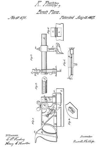
Be it known that I, RUSSELL PHILLIPS, of Gardiner, in the county of Kennebec, and State of Maine, have invented a new and useful Improved Joiners’ Plough ; and I hereby declare the following to be a full, clear, and exact description thereof, which will enable others to make and use my invention, reference being had to the accompanying drawings, forming part of this specification, in which —
Figure 1 shows a side elevation of my invention.
Figure 2, a portion of the top of the horizontal arm, having the graduated scale.
Figure 3 is an end view of my invention, and a view of the top of the end and slides.
Figure 4, a view of a portion of the reverse side of fig. 1.
Figure 5, an edge view of the iron or cutter.
Figure 6, a portion of the adjustable guide or gauge.
Same letters show like parts.
My invention has relation to that tool employed by certain mechanics, joiners, &c., called a plough, and consists in certain improvements thereupon, which may be separately or conjointly used.
I will now describe in detail the different improvements combined in my invention. a shows the groove in which the iron or cutter is placed. It is there secured by means of the clamp b and slide c. Fig. 4 shows the manner in which the slide c is held in place, being by means of a slot and a lip, d, on the side opposite to the one shown in fig. 1. The lip d overlaps the edge of the slot, shown in fig. 4. e is a small projection, to rest against the end of the cutter, so that its edge shall not become dulled by striking or touching any part of the stock. The cutter is fully described hereafter. The cutter, being placed in the groove a, is secured as follows:
As illustrated in fig. 4, the slot in which the slide c moves is curved, so that when the slide is pressed downward, or toward the bottom of the plough, the clamp b is pressed upon the cutter; and when the slide is moved up, the clamp is released or loosened, and its pressure upon the cutter taken away. The clamp b swings on its pivot f. Place the cutter in the groove a, press the slide downward, thus forcing the clamp b upon the cutter, and the cutter is held in place. In this method there is this advantage: With the old form of fastening the cutter or iron, when the wedge that holds it is driven inward by the blow of the hammer or other implement the entrance of the wedge within the stock carries with it, somewhat, the cutter, so that when the cutter has once been adjusted as the mechanic desires, it is made to project further, by being carried inward with the wedge which holds it. Besides this inconvenience, it is difficult to adjust readily. With my invention, the cutter is placed in the desired position, so as to cut into the lumber the desired depth, and can then be immediately fastened by pressing the slide c downward. Moreover, as the clamp b does not slide at all, but simply pushes against the cutter, the cutter is not moved in the least from the desired position, but remains as placed by the user. g, fig. 5, shows the iron or cutter; this has a cutting edge at both ends. These two can be made of different sizes and widths, as seen in the drawing, so as to cut grooves or channels of different widths and sizes. It has a groove, h, to fit over the edge i, to aid in holding it securely. The end of the cutter not employed passes into the recess behind the projection e, and thus its edge is kept from injury till wanted. j is a thumb-piece, for convenience in placing the cutter in its place, and to strike upon with a hammer to move the cutter up or down slightly when it is held by the clamp b. k k are the cutting edges of the iron. l l l l show points projecting beyond the edges k k, which enable the iron to do its work not only with but also across the grain of the wood. These points are sharp, and cut the fibres of the wood before they are reached by the edges k, and thus prevent tearing or breaking out of the work. A shows the single horizontal arm employed in my invention, and upon which the guide or gauge B slides. Upon its top is a channel, with the graduated scale, so that the distance that the gauge is set from the cutter g can be accurately adjusted. Upon this there is no screw-thread, as upon the old form of plough, and, as before remarked, I use but a single arm. This admits of a much easier, more accurate, and readier arrangement for use. The gauge or guide B is made of metal, and has a portion, n, which turns on a hinge, and can be lifted up so as to leave the space o. The object of this will be hereafter described. p are slides, one on each side of the stock of the plough, near the forward end, moving in recesses, and held at any point by the thumb-screw q, which slides in the slot r, shown in fig. 1 by the dotted lines. These slides have at their bottoms the horizontal plates s, one on each side of the plate t. The combination of these devices forms a gauge by which the degree of the penetration of the cutter g into the wood can be governed. By loosening the thumb-screw q, the slides may be raised or lowered, as desired, on either side of t, (see fig. 3.) and, as seen in fig. 1, the cutter is intended to rest against the side of t, so that the depth of the groove to be cut can thus be exactly controlled, and measured by the graduated scale x on the end of the stock, (see fig. 3.) Most of the work to be done by this tool is near the edge of boards or other wood. In such a ease it might happen that the gauge or guide B could not be brought sufficiently near the plate t on account of the projection of the horizontal plates s. This I obviate by the arrangement shown in fig. 6, before described. When the trap an is lifted, as seen in the drawing, the gauge B can be brought quite close to t, one of the plates s entering the space o. In use, one hand of the mechanic rests upon the guide B, where a wooden handle is supplied. The handle upon the stock is seen at D, being placed at the end of the stock, and lower down than is ordinary, with the view that the force applied to the tool is all or nearly all exerted in a horizontal direction, which lessens the labor of using the plough, and makes it more effective. The handle is secured by the removable bolt u, so that if broken the handle can easily be taken off and another substituted. All the parts described, except the arm A, handle D, and a portion of the guide B, are made of metal, which makes the whole tool cheaper, less cumbersome, stronger, and more convenient. The clamp b being made of metal, quite smooth, and slightly rounded, enables the tool to clear itself quite readily of the shavings made in using it. The method of confining the gauge or guide B at any desired point is by the use of the thumb-screw m.
What I claim as my invention, and desire to secure by Letters Patent, is —
1. The reversible cutter shown in fig. 5, as and for the purposes specified.
2. The arrangement of the two slides p p, thumb-screw q, slot r, plates s s, graduated scale x, and plate t, as and for the purposes set forth.
RUSSELL PHILLIPS.
Witnesses:
WILLIAM HENRY CLIFFORD,
HENRY C. HOUSTON.