No. 890,575 – Plane (John L. Pringle) (1908)

[paiddownloads id=”655″]890575


UNITED STATES PATENT OFFICE.

_________________

JOHN L. PRINGLE, OF NEW BRITAIN, CONNECTICUT.

PLANE.

_________________

890,575. Specification of Letters Patent. Patented Jun. 9, 1908.
Application filed November 20, 1905. Serial No. 288,128.

_________________

To all whom it may concern:

Be it known that I, JOHN L. PRINGLE, a subject of the King of Great Britain, and residing at New Britain, in the county of Hartford and State of Connecticut, have invented a new and Improved Plane, of which the following is a specification.

My improvement relates to the class of hand tools used for working upon the surface of boards and the like for smoothing or for grooving, or for similar purposes, and the object of my invention is to provide a plane which shall be simple and cheap in construction, few as to the number of parts, and one which may be put to all of the varied uses to which this class of devices are subjected.

One form of device in the use of which the desired object may be attained is illustrated in the accompanying drawings, in which —

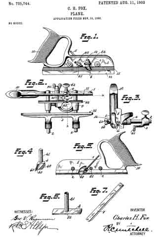
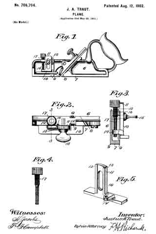
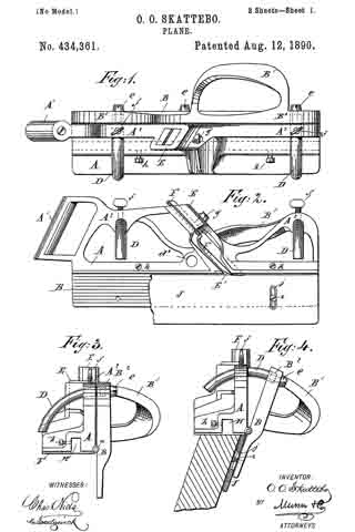
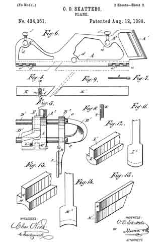
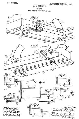
Figure 1 is a perspective view illustrating the bottom and one side of a plane embodying my invention. Fig. 2 is a like view looking from the opposite side of the plane. Fig. 3 is an end view showing the bottom gage-sole used as a side gage. Fig. 4 is what may be termed an illustrative view showing the application of my improvement in cutting a tongue on the edge of a board. Fig. 5 is a like view showing the improvement adapted to the formation of a molding. Fig. 6 is a like view showing the improved tool adapted to cut a groove in the edge of a board. Fig. 7 is a like view showing the improved tool as applied to cutting a concaved surface. Fig. 8 is a view illustrating a modified form of the adjustable gage-sole.

In the accompanying drawings the letter a denotes the body or stock of tlie plane, b a knob or handheld at the forward end, and c a handle located at or near the rear end and on the upper surface of the body part in the usual manner. The body part may be constructed of wood or of any other desired material common to tools of this class. The body part is also provided with a depthwise opening d in which the blade or bit e is located. All of these parts may be of any ordinary and well-known construction.

In carrying out my invention I provide a vertically adjustable secondary sole 1 secured preferably to the side part of the body of the plane, and a laterally adjustable gage-sole 2 which is located underneath the body. The sole 1 includes a plate extendin lengthwise of the body part of the plane, this plate being of proper width and thickness for the purposes in hand, and as shown herein, and as ears 4–5 projecting from the upper edge thereof. These ears are provided with slots 6 through which adjusting studs or screws 7 extend for the purpose of holding the plate in any position of vertical adjustment. An opening 8 is also formed through the ear 5 through which cutting tools or blades of various form may project.

The gage-sole 2 has slots 9 extending laterally thereof formed therein, and studs or screws 10 projecting through these slots into the body of the plane serve as a means of securing the shoe in any position of lateral adjustment. The heads of the screws 10 are located well within the slots, the latter being shouldered to receive the head of the screw. These slots 9 are located at equal distances from the ends of the sole so that the latter may be reversed end for end for certain purposes to be hereinafter described.

It will be seen from the above description and the accompanying illustration that by removing the soles 1 and 2 the plane may be used for all the purposes of a smoothing plane or other surfaces. By placing the secondary sole 1 in position and providing the proper cutting blade the plane may serve the purpose of a plow. By placing the gage-sole 2 and adjusting it in proper position laterally on the bottom of the body part with a proper shaped blade in position, the plane may be used to out moldings of different form. By properly adjusting the soles 1 and 2 with respect to each other and using a blade of proper form articles may be formed of curved shape or round.

The gage-sole 2 is provided on one edge with a recess 14 the walls of which are located preferably at right-angles to each other. When this groove is employed what may be termed the horizontally arranged wall 15 will serve as the bottom proper or sole of the plane, in connection, of course, with the secondary sole 1, and the side or vertically arranged wall 16 will form a gage.

The gage-sole 2 is provided with blade recesses 17 and 18. These recesses are formed to receive one side of the blade of a bit when the tool is used for certain purposes. As shown in Fig. 2, the recess 17 covers one side of the cutting edge of a comparatively wide bit, so that the pidane with such bit may be used as a fillister plane.

By adjusting the gage-sole 2 vertically and laterally, as shown in Fig. 5 of the drawings, and also by adjusting the second ary sole 1 it will be seen that the plane is readily adapted for cutting various forms of moldings, the blade 18 being, of course, properly adjusted.

By adjusting the parts as shown in Fig. 4 the device is adapted for cutting a tongue on the edge of a board, the bit 19 having one of the prongs lying within the opening 8 in the vertical guide, and the other prong extending through the shoulder 15, the edges of these being shown projecting as at 20 in Fig. 4. By reversing the gage-sole 2 and moving it to the position shown in Fig. 6 the device may be used for cutting a groove on the edge of a board, the same knife as shown in Fig. 4 being employed, and that point located within the opening in the secondary sole 1 cutting the groove and the other point being located within the recess 18 in the sole 2, as shown in dotted outline in Fig. 6.

If a circular or curved recess is to be reduced then a blade 21, as shown in Fig. 7 of the drawings, may be used, having its cutting edge of proper form, the extreme curved edge of the blade being located just in advance of the sole 1, and the sole 2 being emlployed as a guide.

In order to adapt the sole 2 for vertical adjustment adjusting supports are mounted on the arms 11, these consisting of a sleeve 22 having set screws 23 with wings 24 bearing adjusting screws 25 which engage threaded sockets in the surface of the gage-sole 2. When the gage-sole 2 is used with the recess 14 facing the secondary sole 1, as shown in Figs. 1, 2, 4, and 5 of the drawings, the screws 10 may be turned out of the stock a or may be removed entirely. It is also obvious that when the gage-sole 2 is used as shown in Figs. 1 and 2, the adjusting screws 25 are not absolutely essential, a though they form a means of support for the projecting edge of the sole.

While the secondary sole 1 has been shown herein as adjustable it is obvious that advantageous results would follow its use in a plane in which it was rigidly secured to the stock without any means of adjustment, but by providing the adjustment I secure all of the advantages present in the late as used in either of the ways mentioned.

In the form of adjustable sole shown in Figs. 1 and 2 the gage-sole is reversed end for end when it is desired to employ the sole as a gage. In Fig. 8 I have adapted this form of the invention so that the sole need not be so reversed when it is to be employed as a gage. In this form of the invention I construct the gage-sole in two parts, a main section 26 and an adjustable section 27. The main section is rovided with a groove 29, and the adjustable section with a shouldered groove 30, a screw 28 to take the place of the screws 10 hereinbefore described for holding the parts in engagement and for holding the sole as a whole in place on the sole or bottom of the plane. It will be seen from this construction that with the parts adjusted as shown in Fig. 8 the device is applicable for the same use as shown in Figs. 1 and 2. By loosening the screw and moving the adjustable section 27 so that the edges are flush, then the sole is adapted for a gage, as illustrated in Fig. 3. It will be noted that the parts 1 and 2 act as soles for the plane, that is, they support the plane in a direction depthwise thereof, the secondary sole 1 supporting the plane when grooves, tongues and the like are being cut, and the gage-sole in connection with the secondary sole supporting the plane as when moldings, and rabbets are cut. It will be noted that when either of the soles 1 and 2 are employed the sole proper of the plane is not in use, the latter mainly being employed when the plane is used as an ordinary surface plane.

I claim:

1. A stock having a bit opening and adapted for use as a surface plane, a secondary sole secured to the side surface of said stock and adjustable depthwise to project below the main sole thereof, and a gage-sole underlying said main sole and adjustable laterally thereof, both of said secondary and gage-soles having openings for the bit and adapted to cooperate therewith in the cutting operation.

2. A stock having a bit opening and adapted for use as a surface plane, a secondary sole secured to the side surface of said stock and adjustable depthwise to project below the sole thereof, a age-sole underlying the main sole and lateragy adjustable thereof, and means for securing the latter sole directly to the under surface of the stock, both of said secondary and gage-soles having openings for a bit to cooperate therewith in the cutting operation.

3. A stock having a bit opening adapted for use as a surface plane, a secondar sole secured to the side surface of the stock and adjustable depthwise to project below the main sole thereof, a reversible gage-sole underlying the said main sole, means for securing said sole in position, both of said secondary and gage-soles having bit openings to cooperate with the bit in the cutting operation.

4. A stock having a bit opening and adapted for use as a surface plane, a secondary sole secured to the side surface of the stock and adjustable depthwise to project below the main sole thereof, a reversible gage-sole underderlying said main sole and adjustable laterally thereof, means for securing said gage-sole directly to the bottom of the stock, both of said secondary and gage-soles having openings for a bit to cooperate therewith in the cutting operation.

5. A stock having a bit opening and adapted for use as a surface plane, a secondary sole secured to the side surface of the stock and adjustable depthwise thereof to project below its main sole, a gage-sole underlying the stock and adjustable vertically and laterally thereof, and means for adjustably securing said gage-sole directly to the under surface of the stock, both of said secondary and main soles having bit openings to cooperate therewith in the cutting operation.

6. A stock having a bit opening, and adapted for use as a surface plane, a secondary sole secured to the side surface thereof and adjustable depthwise to project below its main sole, a gage-sole underlying the stock and vertically and laterally adjustable thereof, means for adjustably securing said sole directly to the under surface of the stock and including slots for the reception of screws and recesses for the reception of the heads thereof, screws for securing said soles, each of said secondary and main soles having openings for a bit to cooperate therewith in the cutting operation.

7. A stock having a bit opening and adapted for use as a surface plane, a secondary sole secured directly to the side surface and adjustable deipthvvise to project below the main sole thereo, a reversible gage-sole underlying the stock and adjustable vertically and laterally thereof, and means for securing said sole directly to the main sole of the stock, both of said secondary and main soles having openings for the bit to cooperate therewith in the cutting operation.

8. A stock having a bit opening and adapted for use as a surface plane, a secondary sole secured to the side surface of the stock and adjustable depthwise to project below the main sole thereof, a gage-sole underlying the stock and reversible thereon and vertically and laterally adjustable thereof , slots in said sole for the reception of screws and recesses for the heads thereof, and screws for securing said sole directly to said main sole, both of said secondary and main soles having openings for a bit to cooperate therewith in the cutting operation.

JOHN L. PRINGLE.

Witnesses:
ARTHUR B. JENKINS,
LENA E. BERKOVITCH.

No. 778,921 – Plane (Justus A. Traut) (1905)

[paiddownloads id=”612″]778921


UNITED STATES PATENT OFFICE.

_________________

JUSTUS A. TRAUT, OF NEW BRITAIN, CONNECTICUT, ASSIGNOR TO THE STANLEY RULE & LEVEL COMPANY, OF NEW BRITAIN, CONNECTICUT, A CORPORATION OF CONNECTICUT.

PLANE.

_________________

SPECIFICATION forming part of Letters Patent No. 778,921, dated January 3, 1905.
Application filed April 27, 1904. Serial No. 205,115.

_________________

To all whom it may concern:

Be it known that I, JUSTUS A. TRAUT, a citizen of the United States, residing at New Britain, in the county of Hartford, State of Connecticut, have invented certain new and useful Improvements in Planes, of which the following is a full, clear, and exact description.

My invention relates to improvements in planes and particularly to planes, in which cutters of various sizes and shapes may be interchangeably employed.

The object of the invention is to provide a construction in which interchanges of cutters may be effected readily and quickly and the operation of the same made reliable and efficient. I have also sought to employ as few parts as possible and to make the construction as economical as its large variety of functions make feasible.

The construction of my invention in the particular form as shown in the drawings consists of a main body portion and a relatively movable section between which the cutting-iron is secured and held in place. Adjustable and interchangeable sole portions are provided by means of which the plane may be guided and the cutting depth regulated with any form of cutting-iron. These adjustable sole portions also support and steady the plane-iron and permit the user to vary the size of the throat or opening in front of the cutting edge.

The details of construction will be more plainly seen on an inspection of the accompanying single sheet of drawings.

Figure 1 is a side elevation of a plane embodying the improvements of my invention. Fig. 2 is a front elevation of the same with the addition of adjustable auxiliary guide. Fig. 3 is a perspective view of a cutting-iron. Fig. 4 is a perspective view of the adjustable and interchangeable sole portions for employment with the plane of my invention.

1 indicates a main body or stock portion of the plane having a guide-blade 2.

3 is a handle which is conveniently provided.

4 is the plane-iron or cutter, which has its cutting edge formed to correspond with the outline of the work which it is desired to turn out.

5 is a suitable clamping-screw for securing the cutter in place.

6 is a screw for adjusting the cutting depth of the plane-iron.

7 and 8 are rods which extend from the body portion of the plane.

9 and 10 are screws for clamping in position.

11 is a sliding section which is upon the rods 7 and 8.

12 and 13 are thumb-screws for clamping the section in place at the distance desired from the main body portion.

14 and 15 are flanges to the front and rear of the throat of the plane which extend downward. The plane-iron when clamped in place is partially supported by the rear flange.

16 and 17 are portions of a sole which is provided to correspond with the shape of the cutter employed to limit the cutting depth and to guide and direct the plane in its operation. These sole portions are formed, preferably, of wood.

18 indicates two screws which take into the sole member 16 for clamping it to the forward flange 14. The flange is preferably provided with keyhole-openings, as shown, so that the sole portion may be removed without entirely removing the screws, it simply being necessary to loosen the screws, slide the sole forward, when the screws may be readily drawn through the enlarged portion. The rear flange 15 is provided with oppositely-positioned keyhole-openings, and the screws 19 coact therewith to clamp the rear sole portion 17 in position. Both of the sole portions may be adjusted front and rear, so as to vary the size of the throat in front of the cutter to bring the rear sole portion up so as to reinforce the cutter and prevent it from chattering or to remove the parts, as may be desired.

20 indicates a section of a molding being cut by a cutter, as shown in the drawings. The form of outline produced will of course depend upon the cutter employed. With my improved invention in use any form of cutter may be employed, it simply being necessary to make use of correspondingly-formed sole portions.

21 indicates a member which may be provided to slide on the rods 7 and 8 and carry an auxiliary guide 22 for fixing the distance of the cutter from the edge of a board, molding, or the like.

23 is a handle which is conveniently provided on this fence portion which serves as a rest for the left hand.

The advantages of my construction will be particularly apparent to those skilled in the manufacture of woodworking-tools and in their use. It greatly reduces the number of parts necessary for a wide variety of work and the expense of the same.

What I claim is —

1. In a plane the combination of a main body member, a member laterally adjustable relatively thereto having flanges projecting downward, said flanges having horizontal openings with enlarged ends, a cutter having an irregularly-shaped edge, a sole member for each of said flanges corresponding in shape to said cutter, and screws for removably securing said sole members to said flanges.

2. In a plane the combination of a main body member, a second member slidable laterally relatively thereto, a pair of flanges projecting downwardly from said slidable member and having an opening between the same, a sole portion carried by each of said flanges, and means for adjusting said sole portions, substantially as described.

3. In a plane, the combination of a body member, a second member laterally adjustable with relation thereto and adapted with said first member to support a plane-iron, a pair of flanges carried by said second member, one in front and the other in the rear, each of said flanges having a plurality of openings elongated liorizontally, the openings in said forward flange being enlarged on their forward ends, the openings in the rear flange being enlarged on their rear ends and a pair of removable sole portions with means coacting with said flanges and the elongated openings therein for securing said sole portions to said flanges.

Signed at New Britain, Connecticut, this 25th day of March, 1904.

JUSTUS A. TRAUT.

Witnesses:
W. J. WORAM,
ROBERT N. PECK.

No. 763,527 – Cutting-Tool (Augustus E. Venn) (1904)

[paiddownloads id=”604″]763527


UNITED STATES PATENT OFFICE.

_________________

AUGUSTUS E. VENN, OF CHICAGO, ILLINOIS.

CUTTING-TOOL.

_________________

SPECIFICATION forming part of Letters Patent No. 763,527, dated June 28, 1904.
Application filed October 5, 1903. Serial No. 175,902. (No model.)

_________________

To all whom it may concern:

Be it known that I, AUGUSTUS E. VENN, a citizen of the United States, residing at Chicago, in the county of Cook and State of Illinois,have invented certain new and useful Improvements in Cutting-Tools, of which the following is a specification, reference being had to the accompanying drawings.

My invention relates to cutting-tools, and particularly to tools adapted to cut grooves in wood or other material to be operated upon; and its object is to provide a new and improved means by which, by the rotation of the cutter in the tool, grooves of different shapes may be cut in the work.

In the drawings, Figure 1 is a longitudinal vertical section on line 1 1 of Fig. 2. Fig. 2 is a top or plan view with one of the handles broken away. Fig. 3 is an enlarged detail, being an isometric view of a part of the support by means of which the cutter is secured to the stock. Fig. 4 is an enlarged detail, being an isometric view of a cross-bar by which one end of the support shown in Fig. 3 is secured to the stock. Fig. 5 is a detail, being a view of the gage, partly broken away; and Fig. 6 is a diagrammatic view showing several shapes which may be given to the cutting edge of the cutter.

As shown in the drawings and as preferably constructed, my invention is embodied in the form of a grooving-plane.

7 indicates the stock, and 8 the bit or cutter.

9 indicates a support which is provided with a cross-piece 10, preferably integral therewith, having its two ends bent up at right angles, as is best shown in Fig. 3, and of such length as to fit closely between the sides of the stock 7. The under side of the support 9 is rounded out, as is best shown in Fig. 3, to conform to the shape of the handle of the bit or cutter 8.

11 indicates a cross-piece which is bent at right angles at its ends and is of such length that the bent-up ends may fit snugly between the sides of the stock 7.

The support 9 is provided at the opposite end from the cross-piece 10 with a projection 12, and the cross-piece 11 is provided with a recessed portion 13 on its upper side, into which the projection 12 will snugly fit.

14 indicates a stirrup which is adapted to surround the rounded portion of the bit or cutter 8 and to pass around the support 9. It is provided on its upper surface with a screw-threaded opening into which a thumb-screw 15 may be screwed.

The bent ends of the cross-piece 10 and of the cross-piece 11 are provided with suitable screw-threaded openings by means of which they may be secured between the sides of the stock. The projection 12 of the support 9 is provided with screw-threaded openings and the recessed portion of the cross-piece 11 with corresponding openings, through which screws may pass to engage the screw-threaded openings in the projection 12 for the purpose of fastening the parts together.

The support 9 is placed between the sides of the stock with its hollowed rounded surface facing downward and is secured to the stock by suitable screws passing through the sides of the stock and into the screw-threaded openings in the bent ends of the cross-piece 10. The stirrup 14 is then placed in position around the support 9, the cross-piece 11 placed in position and fastened by screws to the sides of the stock, and the projection 12 is secured in place in the recess 13 by means of suitable screws.

The bit 8 is cylindrical at its upper end and is provided at its lower end with a cutting portion 16. The bit is provided with a proper clearance above the cutting portion, through which the shavings may pass, as is best shown in Fig. 2.

The cutting edge of the tool may be of various shapes, of which several are illustrated in Fig. 6. The cutter, being placed in position between the support 9 and the stirrup 14, may be adjusted longitudinally of itself, so that a proper amount of the cutting edge may project below the sole of the stock 7 through the usual opening therein, and is locked in position by turning the thumb-screw 15, which will cause the stirrup 14 to move up toward the support 9, firmly binding the cylindrical portion of the cutter between the stirrup and the support. It will be obvious that by rotating the cutter 8 upon its longitudinal axis, which it is obvious can be accomplished by loosening the set-screw 15 and then screwing it home when the desired amount of rotation is made, a different-shaped cutting edge will project below the sole of the stock 7 and a different-shaped groove thereby cut in the work.

17 (see Fig. 2) indicates handles, of which one is cut away upon one side to show the gage hereinafter described. The handles are secured to the stock in any appropriate way.

18 indicates a pin which is cylindrical in shape and has upon its ends screw-threaded portions 19. The sides of the stock 7 are provided with cylindrical openings 20 21, through which the cylindrical pin 18 may pass, and opposite the openings 20 21 are screw-threaded openings 22 23, which are adapted to engage with the screw-threaded ends of the pin.

24 indicates a gage which is provided with a suitable opening through which the pin 18 passes and which is secured in any desired position upon the pin 18 by means of a set-screw 25. It will be obvious that by this construction the gage can be used upon either side of the tool.

That which I claim as my invention, and desire to secure by Letters Patent, is —

1. The combination with a support, of a bit-iron mounted in said support adjustable longitudinally of itself therein and adapted to be rotated on its longitudinal axis and by its rotation to present a different-shaped cutting edge to the work, and means for locking said bit-iron in any desired position, substantially as described.

2. The combination with a plane-stock, of a bit-iron mounted in said stock adjustable longitudinally of itself therein and adapted to project its cutting edge below the sole of said stock, said bit-iron being rotatable on its longitudinal axis and having a cutting edge of such shape that by said rotation of said bit-iron grooves of different shape may be cut, and means for locking said bit-iron in any desired position, substantially as described.

3. The combination with a support of a cutting-tool adjustably mounted in said support adapted to be rotated on its longitudinal axis and having a tubular end provided with a cutting edge adapted by the rotation of said cutting-tool to present a different-shaped cutting edge tothe work, and means for locking said cutting-tool in any desired position, substantially as described.

4. The combination with a stock, a support secured to said stock, a stirrup surrounding said support, a set-screw carried by said stirrup adapted to bear upon one side of said support, a cutter having a shank adapted to be engaged between said support and said stirrup, said cutter being adapted to be rotated upon its longitudinal axis and having a cutting edge of such shape that by the rotation of said cutter grooves of different shape may be cut, substantially as described.

AUGUSTUS E. VENN.

Witnesses:
MINNIE A. HUNTER,
HELEN M. COLLIN.

No. 735,744 – Plane (Charles H. Fox) (1903)

[paiddownloads id=”586″]735744


UNITED STATES PATENT OFFICE.

_________________

CHARLES H. FOX, OF NEW BRITAIN, CONNECTICUT, ASSIGNOR TO
STANLEY RULE & LEVEL COMPANY, OF NEW BRITAIN,
CONNECTICUT, A CORPORATION OF CONNECTICUT.

PLANE.

_________________

SPECIFICATION forming part of Letters Patent No. 735,744, dated August 11, 1903.
Application filed November 15, 1902. Serial No. 131,485. (No model.)

_________________

To all whom it may concern:

Be it known that I, CHARLES H. FOX, a citizen of the United States, residing at New Britain, Hartford county, Connecticut, have invented certain new and useful Improvements in Planes, of which the following is a full, clear, and exact description.

My invention relates to improvements in planes, and particularly to a construction for improving the efficiency and general usefulness of the device in its operation.

The object of my invention is to construct a plane for use in matching boards and the like, which may be adjusted to various widths of cutting-irons. The clogging of shavings which are produced when the plane is in use is avoided. It is also possible to use a beading-iron with the same plane-body when desired.

The invention consists in the improvements to be hereinafter described and shown in the accompanying drawings. The invention is particularly applicable to that class called “matching-planes,” in which a cutter is provided to form the edges of boards in order that they may be matched together. The plane is so constructed as to effect the smooth and certain turning aside of the shavings when theplane is cutting. In the form herein shown the tonguing-iron may be replaced by a beading-iron when the proper adjustments have been made.

Figure 1 is a side elevation of a plane embodying the improvements of my invention. Fig. 2 is a projection showing the under side of the plane. Fig. 3 is a front view of the plane, parts being shown in section on the line X X of Fig. 2. Fig. 4 is a detail of a shaving-deflector. Fig. 5 is an elevation of the inside face of the main stock, parts being shown in section. Fig. 6 is a detail of a gage for limiting the cutting depth when a beading cutter or iron, as shown in Fig. 7, is used.

1 is a main stock portion having a handle 10.

2 2 are rods screwed into the stock portion and upon which slides the part 3, which may be conveniently termed a “fence”.

4 is a sliding section which is mounted upon the rods 2 2 and adapted to be moved toward or away from the stock portion 1.

5 is a tonguing-iron adapted to form the edge of a board into a tongue portion. For this purpose it will be seen that the blade is bifurcated at the lower part, as particularly shown in Figs. 2 and 3. This cutting-iron 5 is mounted in grooves between the adjacent faces of the stock 1 and the sliding section 4. The sliding section is caused to move toward the stock portion 1 and to hold the iron 5 securely in place by means of the thumb-nut 40, which operates on the screw-bolt 41, as seen in Figs. 1 and 2. The stock portion 1 is formed at the lower edge of the outer part, as seen particularly in Fig. 3, with a limiting-surface 11. Similarly the sliding section 4 is provided with a limiting-surface 42, which is, however, oppositely positioned. The fence 3 is provided with a guide-surface 31, which is convenient for use with the plane when it is used as a beading-plane, as will hereinafter be described in connection with the details shown in Figs. 6 and 7.

When the plane is being used to cut with the tonguing-iron 5 in position, the shavings which are cut will be deflected upward by means of the construction which I have provided. The shaving which is formed by the outer right-hand portion of the blade of the tonguing-iron will be deflected inwardly and upwardly by means of the deflector 6, one form of the construction of which is shown in detail in Fig. 4. The shaving as it is being taken is moved forwardly and is caught by the concaved inner surface 60 of the deflector, and thus thrown inwardly to the inside edge of the stock portion 1 and upwardly. This will be seen particularly in Fig. 5. The other shaving, taken by the left-hand portion of the blade 5, will be deflected backward and upward by means of the upper surface of the blade 5 and the concaved upper surface of the sliding section 4 and pass out freely through the curved open space 43. This deflector 6 is situated beyond the outer guide-surface 11 of the stock portion 1 and in this form is mounted in the lug 12. For this purpose the deflector is provided with the shank 61, which may be tightly gripped by means of the thumb-nut 62. The surface of the deflector at 63 is made to coincide approximately with the outer guide-surface of the stock 1 at the point of attachment. At 64 the deflector is formed to coincide with the outer edge of the cutting-blade. The dimensions are such, preferably, that there is but little opportunity for shavings to pass outward from the cutting edge at any other point than that prepared by means of the convexedly-curved surface 60.

It is obvious that some of the same advantages would be had if the deflector 6 were made integral with the stock portion 1. By reason of its being separable therefrom, however, it is possible to employ cutting-irons of various widths with the same main plane structure, using a larger or smaller deflector, as required. There is also another advantage inherent in this structure by reason of the deflector being thus separable from the other parts. By means of this I am able to make this plane interchangeable as a matching-plane which will form a tongue and to use it also as a beading-plane.

Fig. 7 shows the beading-iron 7, which is employed for cutting beads. This beading-iron 7 may be fitted into the guide-slots in the main stock portion and the sliding section 4 adjusted to hold it there by means of the adjusting-screw 40. At such a time the two guiding-surfaces 11 and 42 are in line with the edges of the beading-iron 7, and there is no necessity for the deflector 6. In its place isinserted the gage 8, (shown in Fig. 6,) which has the shank portion 81, adapted to fit in the lug 12 and be engaged by the thumb-nut 62. The edge 82 of this gage is adjusted opposite the outer guide-surface 11 of the stock portion 1, while the lower surface of the gage provides a limiting or guide portion, by means of which the depth of the bead can be made as desired.

The fence 3 may be adjusted upon the rods 2 2 at any suitable distance from the cutting-blade to provide a guide by means of which the cutting edge may be operated at the proper distance from the edge of the board.

It will thus be seen that this construction herein shown and described is adapted to be used efficiently as a matching or tonguing plane and that the shavings caused by the operation of the plane will not clog it or in any other way interfere with its operation.

The plane, moreover, may be used as a beading-plane, thus combining the functions of both and enabling a person to perform both operations with one plane by the simple interchange of parts, which may be readily adjusted to suit different sizes of iron and the addition of which is of but slight expense.

What I claim is —

1. In a plane, the combination of a handle member and a relatively movable member, a plane-iron clamped between the same and protruding beyond the outer surface of the handle member, and means situated on the outer surface of said handle member for deflecting shavings consisting of a body portion having a curved deflecting-surface, a surface fitting close to the plane-handle member and a surface fitting close to the protruding edge of the plane-iron.

2. In a plane the combination of a handle member and a relatively movable member, a plane-iron clamped between the same and protruding beyond the outer surface of the handle part, and a shaving-deflector removably carried by said handle portion, consisting of a body portion and a shank portion said shank fitting into a recess in said handle member.

3. A tonguing-plane having a stock or handle portion, a pair of guide-bars carried thereby, a sliding section mounted on said guide-bars, a cutting-iron secured between the adjacent surfaces of said stock portion and said sliding section, said stock portion having a guiding-surface on the outer side, said cutting-iron projecting a considerable distance outside of said surface, and means for deflecting shavings upward and backward from the cutting edge of said iron.

4. A tonguing-plane including a handle member, guide-rods carried by said member, a member slidably mounted upon said rods and adapted to move relatively to said handle member, a tonguing-iron carried between the said members, a shaving-defiector consisting of a body portion and a shank removably carried by the said handle member and a thumb-screw for securing the shank in a recess in said handle member.

Signed at New Britain, Connecticut, this 13th day of November, 1902.

CHAS. H. FOX.

Witnesses:
H. S. WALTER,
W. J. WORAM.

No. 707,281 – Grooving-Plane (Justus A. Traut) (1902)

[paiddownloads id=”568″]707281


UNITED STATES PATENT OFFICE.

_________________

JUSTUS A. TRAUT, OF NEW BRITAIN, CONNECTICUT.

GROOVING-PLANE.

_________________

SPECIFICATION forming part of Letters Patent No. 707,281, dated August 19, 1902.
Application filed April 28, 1902. Serial No. 104,972. (No model.)

_________________

To all whom it may concern:

Be it known that I, JUSTUS A. TRAUT, a citizen of the United States, residing in New Britain, in the county of Hartford and State of Connecticut, have invented certain new and useful Improvements in Grooving-Planes, of which the following is a specification.

This invention relates to planes; and it consists substantially in the improvements hereinafter particularly described.

The invention has reference more especially to planes such as are employed for cutting or forming grooves in the surfaces of wood and other materials; and the principal object of the invention is to provide a plane of this character with means for effecting the cutting or formation in the surface of the work operated upon of grooves having sides or walls which are curved from end to end, and also to provide means for insuring the evenness of cut or formation of the angular edges of the grooves, as well as the bases and sides thereof.

A further object is to provide a grooving-plane of this special character with means for maintaining or preserving the true curviinear path of the cutting devices of the plane throughout the full extent of the grooves formed thereby, and also to provide means whereby the plane may be readily adapted to the cutting or formation of grooves having sides or walls of different or varying degrees of curvature.

A still further object of the invention is to provide a plane of this character which is exceedingly simple and easily handled in the performance of the work required of it, and also to provide means for meeting all requirements of use of the plane.

The above and additional objects are attained by means substantially such as are illustrated in the accompanying drawings, in which —

Figure 1 is a view in perspective of a grooving-plane structure embodying the essential features of my improvements, the said plane being shown as applied for use in the cutting or formation of curved grooves in the surface of a block of wood or other piece of work operated upon; and Fig. 2 is a bottom plan view of the plane structure, showing an element of my improvements which is omitted from Fig. 1 for the purpose of clearness. Fig. 3 is an enlarged bottom plan view in detail of the cutting devices to more clearly indicate the organization thereof for effecting their respective functions. Fig. 4 is a view in perspective of a part of the gage of the plane, showing a modification thereof for enabling the formation in the work operated upon of grooves having sides or walls of less than a predetermined curvature from end to end.

Before proceeding with a more detailed description it may be stated that while I have herein provided an ordinary grooving-plane with special means for the cutting of grooves having sides or walls which are curved from end to end it will be understood that the adaptability or capacity of the plane for cutting grooves having straight sides or walls from end to end is not altered in the slightest respect. Hence the greater advantage of my improvements. With some kinds of planes for cutting or forming straight-sided grooves in the work operated upon it is usual to employ a suitable gage having a straight edge or face for moving upon or against a corresponding straight edge or face formed on the adjacent part of the work, the said gage serving to guide the cutting devices evenly and being adjustable, by which to vary the distance of the grooves from the edges of the work as well as from each other.

In constructing a grooving-plane according to my present improvements I may employ a well-known form of plane having at one side thereof an adjustable gage formed with a straight edge extending substantially parallel with the sides of the plane-stock, and to said straight edge I apply one or more specially-constructed lateral bearings for the plane structure, said bearings being designed to work upon or against one side or edge of the work in the formation of grooves having either straight or curved sides or walls. For the cutting or formation of straight-sided grooves the adjacent side or edge of the work is made straight, while for the cutting or formation of grooves having curved sides the adjacent side or edge of the work operated upon is constructed in correspondence with the desired degree of curvature of the sides of the grooves to be formed, and it may be stated that the plane structure is equally operative whether the lateral bearings referred to are applied to a concave surface or to a convex surface. In either case the plane structure is constantly deflected to one side in a manner to cause the cutting edge of the bit or plane-iron to follow the desired curvilinear path, and it may be stated that such constant deflection causes the effective edge of the said bit or plane-iron to operate upon the work with a glancing or shearing cut, which is much more effective in removing the necessary quantities of material for the production of the grooves. It may also be stated that in order to insure the evenness of cut of the angular edges of the curved grooves I provide suitable scorers or cutting devices in advance of and slightly beyond the ends of the cutting edge of the plane-iron or bit, said devices operating in a manner and for the purpose hereinafter more fully understood.

Specific reference being had to the accompanying drawings, A represents a grooving-plane embodying my improvements, the same comprising a stock a, having a suitable grip or handle b and provided with the usual bit or plane-iron c, the effective or cutting edge of which is indicated at d. Attached or secured to one side of said stock a is a bracket B, which is provided at points in advance and to the rear of the said cutting edge d with bearings e e, which receive the inner end portions of parallel bars or rods f f, on which are slidably fitted the sleeve portions g g of a guide or gage C, said gage being of ordinary form and constructed with a straight edge or surface h adjacent the said plane-stock a, said sleeve portions being each provided with a set-screw i, working in the side thereof, the said screws being forthe purpose of tightening the gage in diiferent positions of adjustment on said bars or rods f f. To the said straight edge or surface of the said gage I detachably secure one or more lateral bearings or blocks D, having curved faces m, which are designed to bear upon a curved side or edge l of the work operated upon in the application of the plane structure to cut or form curved grooves in the surface of such work, substantially as is indicated at Fig. 1. The said bearings or blocks D may be constructed of wood, metal, or othersuitable material, as is apparent, and they may also be attached or secured to the gage in any suitable manner, screws o o being employed for that purpose in the present instance. Preferably I employ one of such bearings or blocks D at a point to one side of and in advance of the cutting edge d of the bit or plane-iron c and another at a point to the rear of such edge, and thus I may effectually operate the plane structure in the cutting or formation of grooves having either straight or curved sides or walls. It may be stated also that by continuing the curved side or edge l of the work in the formation of a complete circle the plane structure may be operated to cut or form circular grooves in the surface of such work, as is apparent, and it will be understood that by reversing the said plane structure and applying the curved bearings or blocks D to the opposite concave side or edge p of the work similar curved grooves may also be formed in the surface of the work in a like manner. In the use of this described embodiment of my invention for forming curved grooves from end to end of a piece of work, however, the foremost one of the said curved blocks or bearings D of the gage leaves the foremost end of the work before the cutting edge of the bit or plane-iron c has been carried forward far enough to complete the groove, and in the absence of the bearing afforded by said block against the work the entire plane structure is apt to twist or turn to one side or the other from the moving force applied thereto, and thus divert the cutting edge of the plane-iron from the true curvilinear path it is intended to follow. To obviate any such tendency, however, I prefer in most instances to employ substantially a similar block or bearing D2 intermediate the other two and at the same side of the plane-stock substantially coincident with the cutting edge d of the plane-iron, or slightly in advance thereof, and thus it will be seen that the true curvilinear path of the said cutting edge of the plane-iron is always maintained throughout the full extent of the grooves formed thereby. The said intermediate hearing or block D2 may not be constructed the same as the bearings or curved blocks D D; but preferably I construct the same in the present instance of a simple screw r, having a curved or rounded head S to bear against the curved side or edge of the work, said screw being adjustably inserted in a threaded opening therefor extending through the connecting member f2 between said blocks D D and the guide or gage C, as shown. On the outer end of said screw is a suitable jam-nut u for securing the same to the positions to which it may be adjusted. It will be understood that in some instances I may employ the said intermediate bearing D2 alone and dispense vrith the outer bearings or blocks D D for certain kinds of work — as, for instance, when cutting or forming curved grooves of exceedingly limited extent or dimensions from end to end. In most cases, however, I prefer the use or employment of said outer bearings or blocks on account of the stability afforded thereby in the operation of the plane structure, including, as the latter does, the gage and its appurtenances. I may also add that while I have herein illustrated my improvements as applied to a certain form of grooving plane and gage I am not limited to the use of these particular embodiments in the practice of my invention, as is apparent.

In virtue of the curved formation of the surfaces of the bearings or blocks D D when the plane structure is applied in a manner to have such blocks cobperate with the concaved side or edge of the work operated upon the whole plane structure is deflected inwardly in such manner as to keep the cutting edge of the plane-iron in the desired curvilinear path, all as hereinbefore mentioned, and it may also be said that substantially the same effect is had when the said bearings or blocks D D are applied to the convex side or edge of the work.

It should be explained at this point that if the cutting edge of the plane-iron should be made as wide as the predetermined width of groove to be formed in the work, then as a result of the deflection of the plane structure already explained the said cutting edge would tend to ride over the edges of the grooves, and thus mutilate said edges or destroy the angular symmetry thereof. To guard against any such destructive tendency, I construct the cutting edge of the plane-iron a little less in width than the intended width of the groove and I locate in advance of said cutting edge what I term “scoring” devices 2 2, which are arranged slightly to one side of or beyond the ends of the cutting edge d or at a distance apart substantially equal to the width of the groove to be formed. In this way the said scoring devices form parallel grooves in the work in advance of the main groove formed by the said cutting edge d, and thus is the latter enabled to properly conform to the predetermined curvilinear path therefor without in any manner injuring the edges of the grooves. As the plane structure is operated over the surface of the work, the bed of material remaining between the narrow parallel grooves formed by said scoring devices is successfully removed in an even manner by the slight shearing effect given to the cutting edge of the said plane-iron, as already mentioned.

I am not limited to the specific construction or organization of elements herein illustrated and described, and it is evident that it is immaterial at which side of the plane-stock the adjustable gage and its appurtenances are supported. It should be added as another reason therefor that the cutting edge d of the bit or plane-iron c is made less in length than the predetermined width of the curved groove to be formed in the work to enable the same to partake of the deflection of the plane structure without upturning or tearing away the edges of the groove, and it is also added that the scoring devices 2 2 in advance of said cutting edge d are each held to one side of the plane-stock by means of a screw 6, so as to enable said devices to be detached at any time for sharpening purposes or to be replaced by others.

In order to enable the cutting or formation of short curved grooves to be edected by the use of my improvements, more especially when the lateral bearing-blocks are made to ride a concaved or inner curved side or surface of the work operated upon, I make said bearing-blocks adjustable to be moved toward each other and secured in position, and while any suitable means may be employed for this purpose I have herein indicated a simple construction therefor at Fig. 4. Thus in said Fig. 4 I construct the straight portion or surface h2 of the gage C with two oblong openings or slots 8 8, passing through which are tightening or fastening screws 9 9, which enter the lateral bearings or blocks D3 D3. It is evident that by loosening said screws they and the said bearings or blocks may be adjusted along said straight portion or surface h2, after which the screws may be again tightened to secure the blocks in place.

Having described my invention, I claim —

1. A grooving-plane structure comprising a stock having a bit, and means supported substantially in line with the cutting edge of said bit for engaging a curved surface of the work operated upon, said means consisting of a screw having a curved head.

2. A grooving-plane structure comprising a stock having a bit, a gage lateral to the stock, and means on the gage substantially in line with the cutting edge of said bit for engaging a curved surface of the work operated upon, said means including a screw working in an opening in the gage and having a curved head.

3. A grooving-plane structure comprising a stock having a bit, means lateral to the stock both in advance of and to the rear of the cutting edge of said bit for engaging a curved surface of the work operated upon, and a screw supported substantially in line with said cutting edge and having a curved head also engaging the curved surface of the work.

4. A grooving-plane structure comprising a stock having a bit, a gage lateral to the stock, means on the gage both in advance of and to the rear of the cutting edge of said bit for engaging a curved surface of the work operated upon, and a screw supported by the gage substantially in line with the said cutting edge and having a curved head also engaging the curved surface of the work.

5. A grooving-plane structure comprising a stock having a bit, means lateral to the stock both in advance of and to the rear of the cutting edge of said bit for engaging a curved surface of the work operated upon, and a screw supported in line with said cutting edge and having a curved head also engaging the curved surface of the work, said means each being adjustable toward the other.

6. A grooving-plane structure comprising a stock having a bit, a gage lateral to the stock, means on the gage both in advance of and to the rear of the cutting edge of said bit for engaging a curved surface of the work operated upon, and a screw supported by the gage substantially in line with the cutting edge and having a curved head also engaging the curved surface of the work, said means each being adjustable toward the other.

7. A grooving-plane structure comprising a stock having a bit, a gage lateral to the stock, means on the gage both in advance of and to the rear of the cutting edge of said bit for engaging a curved surface of the work operated upon, and a screw supported by the gage substantially in line with said cutting edge and having a curved head also engaging the curved surface of the work, said gage being adjustable toward and from the stock.

8. A grooving-plane structure comprising a stock having a bit, a gage lateral to the stock, means on the gage both in advance of and to the rear of the cutting edge of said bit for engaging a curved surface of the work operated upon, and a screw supported by the gage substantially in line with said cutting edge and having a curved head also engaging the curved surface of the work, said gage being adjustable toward and from the stock, and said means each being adjustable toward the other.

9. A grooving-plane structure comprising a stock having a bit, means lateral to the stock both in advance of and to the rear of the cutting edge of said bit for engaging a curved surface of the work operated upon, a screw supported substantially in line with the cutting edge and having a curved head also engaging the curved surface of the work, and scoring devices located beyond the ends and in advance of the said cutting edge.

10. A grooving-plane structure comprising a stock having a bit, a gage lateral to the stock, means on the gage both in advance of and to the rear of the cutting edge of said bit for engaging a curved surface of the work operated upon, a screw supported by the gage substantially in line with the cutting edge and having a curved head also engaging the curved surface of the work, and scoring devices located beyond the ends and in advance of the said cutting edge.

11. A grooving-plane structure comprising a stock having a bit, a gage lateral to the stock, a block on the gage both in advance of and to the rear of the cutting edge of said bit and having acurved surface for engaging a curved surface of the work operated upon, and a screw supported by the gage intermediate of said blocks and having a curved head also engaging the curved surface of the work.

12. A grooving-plane structure comprising a stock having a bit, a gage lateral to the stock, a block on the gage both in advance of and to the rear of the cutting edge of said bit and having a curved surface for engaging a curved surface of the work operated upon, and a screw supported by the gage intermediate of said blocks and having a curved head also engaging the curved surface of the work, said blocks being adjustable toward each other longitudinally of the gage, and said screw being adjustable toward and from the stock.

13. A grooving-plane structure comprising a stock having a bit, a gage parallel with and lateral to the stock, means on the gage both in advance of and to the rear of the cutting edge of said bit for engaging a curved surface of the work operated upon and adapted to deflect the structure laterally in the planing movements thereof to cause said cutting edge to follow a path parallel with such curved surface, and similar means substantially in line with said cutting edge, said gage being adjustable toward and from the stock, and each of the means specified being adjustable on the gage and consisting of a lateral bearing or block having a curved surface.

14. A grooving-plane structure comprising a stock having a bit, a gage parallel with and lateral to the stock, means on the gage both in advance of and to the rear of the cutting edge of said bit for engaging a curved surface of the work operated upon and adapted to deflect the structure laterally in the planing movements thereof to cause said cutting edge to follow a path parallel with such curved surface, and a screw supported by the gage substantially in line with said cutting edge and having a curved head also for engaging the curved surface of the work, said gage being adjustable toward and away from the stock, and said means each being adjustable on the gage and consisting of a lateral bearing or block having a curved surface.

15. A grooving-plane structure comprising a stock having a bit, a gage parallel with and lateral to the stock, means on the gage both in advance of and to the rear of the cutting edge of said bit for engaging a curved surface of the work operated upon and adapted to deflect the structure laterally in the planing movements thereof to cause said cutting edge to follow a path parallel with such curved surface, sirnilar means substantially in line with said cutting edge, and scoring devices located beyond the ends and in advance of the cutting edge, said gage being adjustable toward and from the stock, and each of the means specified being adjustable on the gage and consisting of a lateral bearing having a curved surface.

16. A grooving-plane structure comprising a stock having a bit, a gage parallel with and lateral to the stock, means on the gage both in advance of and to the rear of the cutting edge of said bit for engaging a curved surface of the work operated upon and adapted to deflect the structure laterally in the planing movements thereof to cause said cutting edge to follow a path parallel with such curved surface, a screw supported by the gage substantially in line with said cutting edge and having a curved head also for engaging the curved surface of the work, and scoring devices located beyond the ends and in advance of the cutting edge, said gage being adjustable toward and from the stock, and said means each being adjustable on the gage and consisting of a lateral bearing or block having a curved surface.

JUSTUS A. TRAUT.

Witnesses:
EBEN STRONG,
FRANK S. TRAUT.

No. 706,704 – Plane (Justus A. Traut) (1902)

[paiddownloads id=”566″]706704


UNITED STATES PATENT OFFICE.

_________________

JUSTUS A. TRAUT, OF NEW BRITAIN, CONNECTICUT.

PLANE.

_________________

SPECIFICATION forming part of Letters Patent No. 703,704, dated August 12, 1902.
Application filed May 20, 1901. Serial No. 60,992. (No model.)

_________________

To all whom it may concern:

Be it known that I, JUSTUS A. TRAUT, a citizen of the United States, residing in New Britain, in the county of Hartford and State of Connecticut, have invented certain new and useful Improvements in Planes, of which the following is a specification.

This invention relates to improvements in planes, and more particularly to that style of plane known as a “dado-plane,” and has for its object to provide adjustable means for limiting the depth to which the cutting of the plane may proceed.

A further object is to provide a plane of this character with a supplemental sole cooperative with the sole and which is easily and quickly adjustable and which can be securely maintained in its adjusted position.

A further object of my invention is to provide adjusting means which will also cooperate with the securing means for the purpose of maintaining the sole in its adjusted position.

In the drawings accompanying and forming part of this specincation is shown my invention applied to a form of dado-plane, which may be the preferred form, if desired.

Figure 1 is an elevation of a plane having my invention applied thereto. Fig. 2 is a plan view of the forward end of the plane, showing the same on a somewhat larger scale. Fig. 3 is a cross-section on the line 3 3, Fig. 2. Fig. 4 is a form of adjusting-screw, and Fig. 5 is a form of supplemental sole or guide.

Like characters of reference designate the same parts in the various figures, wherein a plane-stock is represented generally by 6, having a sole 7, through which works a suitable plane-iron 8 and in connection with which are adjustable guide-knives 9 9. To the plane-stock is iitted a supplemental sole 10, having a projecting slotted arm 11, ways or guides 12 and 13, and a tapped boss 14. The supplemental sole is adapted to be secured to the plane-stock, generally at one side of the stock and forward of the mouth, by means of a set-screw 15 traversing the slotted arm and tapped hole in the plane-stock. The way 13 is shown as being of greater projection than the way 12, and it is adapted to enter and slide in a groove or guide 16 in the plane-stock; to prevent lateral movement or oscillation of the supplemental sole, the other way 12 being adapted to slide upon a face provided for it on the side wall of the plane-stock. The way 13 is shown in the drawings as having square corners and a fiat face, although any other or convenient form of way may be employed. The plane-stock is provided with a tapped boss located above the tapped boss in the supplemental sole. These bosses are adapted to be traversed by an adjusting-screw 17, preferably made with right and left threads of differential pitch. This screw is adapted for raising and lowering the supplemental sole, and it cooperates with the set-screw for maintaining the supplemental sole in its adjusted position.

It will be readily seen that by loosening the set-screw the supplemental sole may be raised and lowered at will by means of the screw 17. If the adjusting-screw is made with the portion traversing the boss in the stock of a greater number of threads to the inch than the part of the screw which traverses the boss in the supplemental sole, the head of the adjusting-screw will not have to be raised as great a distance as if both screw-threads were provided with the same number of threads, and hence I preferably employ such an embodiment herein. With such an organization increased range of adjustments of the supplemental sole may be affected by a very slight turn imparted to said screw. It will be observed that the said right and left hand differential adjusting-screw 17 is also of different diameters in its length, the portion thereof having the least number of threads being less in thickness or diameter than the portion having the greatest number of threads thereon, such construction permitting the insertion or passage of the said adjusting-screw through the tapped opening in the boss of the stock, it being evident that if the screw was of the same diameter throughout it could not be passed through such opening on account of its differential character and the right and left hand directions of its threads, the said tapped opening in the boss referred to being only adapted to receive that portion of the screw of the greatest diameter and greatest number of threads per inch ratio.

By the organization of the parts that is contemplated in my invention a screw of the general construction described, after adjustment of the supplemental sole, will not be readily jarred out of place, and it will cooperate with the ways and the set-screws for maintaining the parts in their adjusted position, so that although the supplemental sole has but one adjusting device and but one retaining device per se it has two maintaining devices aside from the ways, rendering all pivotal action impossible, so that the greatest accuracy of adjustment is possible with this plane, which in fine work it is essential should be had. Otherwise the tool would not do neat and accurate work.

It will thus be seen that the differential thumb-screw 17 may be assembled by passing its small-diameter coarsely-threaded tip end through the large hole in the stock and then engaging said tip with the small threaded hole in the lug 14 upon the supplemental sole and also engaging the finely-threaded large-diameter upper end of the screw with the hole in the stock. Then the transverse clamping-screw 15 is inserted through the vertical slot in the supplemental sole, the shank of said clamping-screw thereupon serving to limit the vertical adjustment of the supplemental sole, so that the thumb-screw 17 cannot be withdrawn from the latter, this being a desideratum, since it is required in this class of tools that when once assembled for use no operation such as is necessary for its adjustment shall be capable of taking the tool apart. In practice the upper end of the screw 17 is provided with right-hand thread and the lower end with left-hand thread, as illustrated.

It will be observed that I avoid slotting or forking, and hence weakening the stock, as is usual where adjusting-screws are used having double collars, and I also avoid the expense of applying a collar to a screw after the insertion thereof in the stock, as well as the consequent additional complexity of construction and looseness of parts, such small pieces becoming loosened quickly and seriously impairing the usefulness of the plane, rendering the same of a ramshackle character. By my invention an ease and accuracy of adjustment are secured which are not found in planes having ordinary screws and collars and other loose parts. The integrality of construction of the screw and the absence of small accessories thereto gives firmness of feeling to the action of the slide, so that the workman can tell exactly what he is doing. All this is accomplished without a single piece of any kind being added to the mechanism, thus securing a minimum of both weight and expense. The adjustment is reduced absolutely to the fewest elements. No smaller number of elements can be employed, and, moreover, no greater advantages can be obtained from the use of a greater number of parts. Thus is satisfied the imperative requirements in this art — of lightness, rigidity, simplicity, inexpensiveness, durability, and delicacy of action.

Although I have shown a set-screw and a right and left differential screw, yet any other or convenient mechanical devices which in practice may be found desirable may be employed without departing from the spirit of my invention.

Having described my invention, I claim —

1. In a plane, the combination with a stock having a sole, of a supplemental sole, a threaded hole in the stock, a differently-threaded hole of different diameter in the sole, and a single thumb-screw having correspondingly-threaded shanks of large and small diameters working in both of said holes.

2. In a plane, the combination with a stock having a sole, of a supplemental sole, a hole in said stock, a hole in said supplemental sole, one of said holes being of larger diameter than the other and one of said holes having a right-hand thread and the other having a left-hand thread, and a screw having shanks of corresponding sizes and threads and working in both of said holes.

3. In a plane, the combination with a stock having a sole, of a supplemental sole, a hole in said stock having a right-hand thread, a hole of smaller diameter in said supplemental sole, and having a left-hand thread, and a screw having shanks of corresponding sizes and threads and working in said holes.

4. In a plane, the combination with a stock having a sole, of a supplemental sole, a hole in said stock having a right-hand thread, a hole of smaller diameter in said supplemental sole and havinga left-hand thread of coarser pitch, and a screw having portions of corresponding sizes and threads and working in said holes.

5. In a plane, the combination with a stock having a sole, of a supplemental sole; a threaded hole in the stock; a differently-threaded hole of smaller diameter in the sole; a single thumb-screw having differently-threaded shanks of large and small diameters working in said holes; and means for limiting the movement of said supplemental sole so as to prevent the withdrawal of said screw from said sole.

6. In a plane, the combination with a stock having a sole, of a supplemental sole; a hole in said stock; a hole in said supplemental sole; one of said holes being of larger diameter than the other, and one of said holes having a right-hand thread and the other having a left-hand thread; a screw having portions of corresponding sizes and threads and working in both of said holes, and detachable means for clamping said supplemental sole to the stock; said clamping means including a part which limits the movement of said supplemental sole so as to prevent the withdrawal of said screw therefrom.

7. In a plane, the combination with a stock having a sole, of a supplemental sole; a hole in said stock having a right-hand thread 5 a hole of smaller diameter in said supplemental sole having a left-hand thread; a screw having portions of corresponding sizes and threads and working in said holes; a slot in said supplemental sole, and a transverse clamping-screw passing through said slot and engaging said stock; the play of said slotted sole upon the shank of said clamping-screw being insufficient to permit the withdrawal of said adjusting-screw from the supplemental sole.

8. In a plane, the combination of a stock, a supplemental sole, and a screw having near its head a finely-threaded shank portion which is threaded into a hole in said stock, and also having at its tip a coarsely-threaded shank portion of smaller diameter which is threaded into a hole in the supplemental sole.

9. In a plane, the combination with a stock and a supplemental sole adjustable up and down thereon, of an up-and-down thumb-screw having at its upper end a threaded portion of fine pitch which works in a corresponding hole formed in the upper portion of the stock, and also having at its lower end a coarsely-threaded portion of smaller diameter which works in a corresponding hole in the supplemental sole.

10. In a plane, the combination with a stock; and a supplemental sole adjustable up and down thereon, of an up-and-down thumb-screw having at its upper end a right-hand-threaded portion of line pitch which works in a corresponding hole in the stock, and also having at its lower end a left-hand-threaded portion of smaller diameter and of coarse pitch which works in a corresponding hole in the supplemental sole.

JUSTUS A. TRAUT.

Witnesses:
H. C. HINE,
F. L. TRAUT.

No. 434,361 – Plane (Ole O. Skattebo) (1890)

[paiddownloads id=”464″]434361


UNITED STATES PATENT OFFICE.

_________________

OLE O. SKATTEBO, OF HANNAFORD, NORTH DAKOTA,
ASSIGNOR OF ONE-HALF TO JORGEN HANSON, OF SAME PLACE.

PLANE.

_________________

SPECIFICATION forming part of Letters Patent No. 434,361, dated August 12, 1890.
Application filed March 8, 1890. Serial No. 343,098. (No model.)

_________________

To all whom it may concern:

Be it known that I, OLE O. SKATTEBO, of Hannaford, in the county of Griggs and State of North Dakota, have invented a new and Improved Plane, of which the following is a full, clear, and exact description.

My invention relates to improvements in carpenters’ planes; and the object of my invention is to provide a plane that will be equally efficient as a square or bevel plane, and that may be readily converted from one to the other, and also to provide a plane in which a great variety of tools may be inserted, so that the plane maybe used for matching, rabbeting, grooving, rounding, beading, and the like.

To this end my invention consists in a plane constructed substantially as hereinafter described and claimed.

Reference is to be had to the accompanying drawings, forming a part of this specification, in which similar letters of reference indicate corresponding parts in all the figures.

Figure 1 is a plan view of the plane; Fig. 2, a side elevation of the same with a portion of the guide-plate broken away; Fig. 3, an end view of the device as adjusted for a square plane, but with the guide-strip removed; Fig. 4, an end view of the same adjusted for a bevel-plane; Fig. 5, an end view of the plane adjusted for rabbet-work; Fig. 6, a side elevation of one of the separable parts of the plane with a portion of one hinge in section; Fig. 7, a detailed view of the pintle of the plane-hinges; Figs. 8 and 9, side elevations of the strips used for matching and rabbeting; Fig. 10, a transverse section on the line x x, of Fig. 8; Fig. 11, a detail view in elevation of the grooving-knife; Fig. 12, a perspective view of the grooving-guide; Fig. 13, a perspective view of the rounding or molding guide; Fig. 14, a front elevation of a corresponding knife for same, and Fig. 15 a perspective view of a ripping-guide.

The body or frame of the plane consists of two longitudinally-separable parts A and B, which are so hinged together by hinges a, near the ends thereof, that they may be placed at various angles with each other. The hinges a are attached to the inner edge of the part A, which carries the planer-knives, and to the upper edge of the part B, so that when the parts are shut closely together, the part B will shut against theinner edge of the part A, so as to project downwardly at right angles with the same. The hinges a are also provided with a removable pintle b, which fits in the knuckles a’ of the hinges, and which is screw-threaded at the end to engage a similar thread upon the interior of the inner knuckle of the hinges, so that the pintle may be easily removed and the parts A and B of the frame separated.

The parts A and B are each provided with a suitable handle A’ B’, by which the plane may be pushed or pulled, as the case may be, and with upwardly-extending braces A2 and B2, which fit closely together, and which are provided with corresponding holes d, through which extend the curved arms D or straight arms D’, said arms being attached to the braces B2 by the screws e, which fit a screw-thread in the ends of said arms, and being retained in the braces A2 by the binding-screws f which project through from the top of said braces and impinge upon said arms, so that the parts A and B are adjustably connected by the arms D and D’ and their attaching-screws.

In order that there may be no movement whatever between the parts A and B when adjusted by the straight bars, I provide other openings d’ below and between the upper openings d, one of said openings d’ being shown in Fig. 2 and 5. The lower bar D’ passes through said opening d’.

The part A of the frame is provided with the usual slide E, in which a knife F is inserted, with a set-screw g, which projects through the slide and holds the knife in position therein, and with a slot E’, through which the knife extends below the bottom of the plane. The part A is also provided upon the bottom with a longitudinal groove or recess H, which extends the entire length thereof, in which the various guides are inserted, as hereinafter described, and with screws h, which project through the wall of said groove, by means of which the guides are retained in the groove.

Attached to the inner side of the part B is the vertically-adjustable guide-plate J, which is of the same length as the part B and extends below the lower edge thereof. It serves as a guide to the plane, and is attached to the part B of the frame by the screws i, which project through vertical slots j in the plate into the side of the part B, so that by loosening said screws the plate may be easily adjusted upon the frame.

When a square edge is to be planed, the parts A and B of the frame are locked together, so that they will be at right angles with each other, as best shown in Fig. 3, and the plane is used as an ordinary square-edge plane. When a beveled edge is to be planed, the curved arms D are inserted in the holes d, and the parts are swung apart upon their hinges till the desired bevel is obtained, when they are retained in this position by tightening the binding-screws f upon the arms D. This position is best shown in Fig. 4. The plane is then used as an ordinary bevel-plane. To facilitate the adjustment to any bevel, the curved arms D should be marked off into degrees, and then when the proper degree is indicated upon the arms they may be secured in position as desired.

If the plane is to be used as a matching-plane, the guide-strips K and K’, which are of about the width of the groove to be planed, are inserted in the groove H in front of and behind the slot E’. A suitable narrow knife is inserted in the slide E so as to project down between the guide-strips K and K’, and the plane is used as an ordinary matching-plane. If a tongue is to be cut, the guide-strips K and K’ are removed and a suitable knife for tongue-planing inserted in the slide E.

If the plane is to be used as a rabbet-plane, the curved arms are removed from the holes d and the straight arms D’ inserted, the pintle b is removed from the hinges a, and the plane will then be laterally adjustable. The arms D’ are held in a desired position by the binding-screws f in the same way that the arms D are secured, and the arms should be marked off into fractions of an inch, that they may be easily adjusted. The guide-strip K’ and the guide-strip K, which is provided with a vertically-adjustable knife l, which is attached thereto by a screw m, projecting through a slot l’ thereof, are inserted in the groove H and held by the screws h. A suitable knife is inserted in the slide E, and the plane is ready for rabbet-work. In using it as a rabbet-plane and for other similar work the distance of the knife from the edge of the board is regulated by the arms D’ and binding-screws f as the part B of the frame, which extends down the side of the board, may be brought as near to the part A as desired, and is secured in that position, as described. When used for rabbet-work, the knife l will project a desired distance below the guide-strip K, and, entering the board to be planed, will cut a smooth surface for the shoulder of the rabbet.

In Figs. 11 and 12 I have shown a knife and guide for grooving. The guide L is provided with an upwardly-projecting tongue L’, which fits into the groove H of the plane, is held therein by the screws h, and is provided with a rounding lower face corresponding with the groove to be planed. The knife L2 has a convex edge corresponding to the shape of the lower surface of the guide L. It is inserted in the slide E of the plane in the usual manner, and the plane is used as an ordinary grooving-plane.

In Figs. 13 and 14 I have shown a knife and guide for rounding or molding. The guide M is provided with a tongue M’ which fits the groove H, and which is used in the same way as the grooving-guide. The rounding-guide, however, is provided with a concave lower surface and the plane with a corresponding knife M2, having a concave cutting-edge.

When the plane is to be used as a ripping-plane, the ripping-guide N, having a narrow edge N’, is secured in the groove H, a suitable ripping-knife is inserted in the slide E, and the plane is used as a ripping-plane.

I might show many more tools that could be used with the plane; but without going further into details it is evident that by making a suitable guide to fit the groove H and providing a corresponding knife the plane may be used to produce almost any form.

It will be seen from the foregoing description that a person by having a plane as described, with the accompanying guides and knives, can do the work now performed by a great many separate planes.

Having thus described my invention, what I claim as new, and desire to secure by Letters Patent, is —

1. A plane consisting in a stock or knife-carrying portion, a longitudinal guide adapted to be held parallel with or at any desired angle to the said stock, a separable hinge-joint to connect the two parts when the guide is to be held at an angle, and interchangeable rods and set-screws for holding the guide parallel with or at an angle to said stock, substantially as set forth.

2. A plane consisting, essentially, of two longitudinally-separable parts, the knife-carrying part having a longitudinal slot in the bottom thereof, in which any desired form of guide maybe inserted, and having a suitable slide in which a knife may be secured to match said guide, substantially as described.

3. The combination, with the plane A B, the part A having a longitudinal groove in the bottom thereof, as shown, of the rabbet-guide K, adapted to fit in said groove, and having a vertically-adjustable knife l affixed thereto to cut the shoulder of the rabbet, substantially as described.

OLE O. SKATTEBO.

Witnesses:
MARTIN MOSSING,
ERIK AUSTAD.

No. 399,287 – Gage Attachment For Planes (George H. Russell) (1889)

[paiddownloads id=”446″]399287


UNITED STATES PATENT OFFICE.

_________________

GEORGE H. RUSSELL, OF PITTSFIELD, MASSACHUSETTS.

GAGE ATTACHMENT FOR PLANES.

_________________

SPECIFICATION forming part of Letters Patent No. 399,287, dated March 12, 1889.
Application filed October 27, 1888. Serial No. 289,264. (No model.)

_________________

To all whom it may concern:

Be it known that I, GEORGE H. RUSSELL, a citizen of the United States, residing at Pittsfield, in the county of Berkshire, State of Massachusetts, have invented certain new and useful Improvements in Gage Attachments for Planes, of which the following is a specification, reference being had therein to the accompanying drawings.

This invention has relation to heading or grooving planes, and especially to an adjusting attachment for the same, whereby said plane is adapted for forming beads or grooves of varying widths; and among the prime objects in view are to provide a simply constructed and applied gage that can be easily and quickly adjusted for different-sized grooves or heads, which grooves or beads shall be uniform.

Other objects and advantages of the invention will hereinafter appear, and the novel features thereof will he particularly pointed out in the claim.

Referring to the drawings, Figure l is a perspective of an adjustable attachment for planes constructed in accordance with my invention, and Fig. 2 is a plan of a plane provided with such an attachment.

Like numerals of reference indicate like parts in both the figures of the drawings.

1 represents a longitudinal plate or bar, which may be either straight or curved to fit the side wall of a plane, and which is perfo-
rated at its opposite ends, as at 2, for the passage theirethrough of an adjusting clamping-bolt, 3, the inner ends of which are formed with screw-threads for the reception of thumb-screws 4, and the opposite ends of which are bent at a right-angle, as at 5, so as to embrace the opposite side wall of a plane, 6, whereby said plane may be tightly clamped to the gage.

From the plate 1, and near each of its ends, there project lateral rods 7, which, for a purpose hereinafter apparent, may he provided with a scale.

8 represents the adjusting-bar, which is designed to ride against the side of the work in which the head or groove is being formed, and it is provided with upwardly-disposed opposite arms, 9, terminating in laterally-bored bosses 10, adapted to receive and ride upon the rods 7, and held in position upon said rods by means of set-screws 11, inserted through vertical openings in the bosses, which screws rest upon the rods 7.

By adjusting the gage-bar S upon the rods 7 and securing the same by means of the set-screws 11 it is apparent that beads or grooves of any desired width may be formed, in that, if the plane is adapted for grooving one-fourth inch, to groove one-half inch it is only necessary, after a one-fourth groove has been formed, to set the gage-rod back another quarter-inch and form a second groove, thus increasing indefinitely the capacity of the plane. The device will also he found convenient when a series of boards or posts are to be grooved, each of the grooves or heads to be a predetermined distance from the edge of the work.

By this device uniform work is accomplished.

Having described my invention and its operation, what I claim is —

The herein-described adjnstable gage attachment for planes, consisting of the bar 1, having end perforations, 2, provided with the L-shaped clamping-bolts 3, bent, as at 5, adapted to embrace a plane at its ends, and set-nuts 4, and opposite bars, 7, projecting from the bar 1, and the gage-bar 8, having upwardly-disposed arms 9, terminating in perforated bosses 10, for the reception of the bars 7, and having set-screw 11, substantially as specified.

In testimony whereof I affix my signature in presence of two witnesses.

GEORGE H. RUSSELL.

Witnesses:
JOSEPH MASLEN,
E. M. WOOD.

No. 348,198 – Variable Bench-Plane (Amos Fales) (1886)

[paiddownloads id=”413″]348198


UNITED STATES PATENT OFFICE.

_________________

AMOS FALES, OF ROCKFALL, CONNECTICUT.

VARIABLE BENCH-PLANE.

_________________

SPECIFICATION forming part of Letters Patent No. 348,198, dated August 31, 1886.
Application filed July 29, 1885. Serial No. 172,960. (Model.)

_________________

To all whom it may concern:

Be it known that I, AMOS FALES, residing in Rockfall, in the county of Middlesex and State of Connecticut, have invented Improvements in Variable Bench-Planes; and I do hereby declare that the following is a full and exact description thereof, reference being had to the accompanying drawings, making part of this specification.

Figure 1 is a view in perspective of the main stock of the instrument as provided with my improved means of applying the fillister and grooving attachments with reversible and adjustable fence; Fig. 2, a front end view of the same; Fig. 3, a side view of one of the attaching-brackets; Fig. 4, a top view of the same; Fig. 5, a front end view of the instrument having its fence reversed for making a front fillister; Fig. 6, a front view of a set of dado-spurs of different sizes; Fig. 7, a side view of one of the spurs; Fig. 8, a side view of the main stock, with a pair of form-plates attached thereto, showing the manner in which the dado-spurs are applied; Fig. 9, a bottom view of the same; Fig. 10, a front view of a spur having only one cutting-point; Fig. 11, a side view of the main stock provided with thin removable extension-flanges for cutting extremely-narrow grooves; Fig. 12, a bottom view of the same; Fig. 13, a front end view of the same; Fig. 14, a side view of the front form-plate constructed to be adjustable lengthwise; Fig. 15, aside view of a special form of cutter used; Fig. 16, an end view of the same; Fig. 17, a top view of a cutter provided with a cap-iron attached thereto; Fig. 18, a side edge view of the same; Fig. 19, a bottom view of the same; Fig. 20, a front view of forward form-plate having a dado-spur.

Like letters designate corresponding parts in all of the figures.

The general construction of the bench-plane on which the present improvements are based is shown and described in the previous patents granted to me March 7, 1882, and April 1, 1884, and numbered, respectively, 254,542 and 295,916. Especially I will refer to one or the other of those patents for the construction of the main stock A, with its flange a, for attaching other parts of the instrument thereto, and means for securing the cutters B therein, the front and back form-plates, C D, and the reversible fence E.

Referring to those former patents, it will be noted that the front and back form-plates are attached to the downwardly-projecting stock-flange a, each by means of a single set-screw, b, fitting in a vertical notch or slot, c, of the form-plate flange d.

The first improvement herein to be described consists in the means whereby grooving and filiister attachments are applied, as shown in Figs. 1, 2, 3, 4, and 5. Two brackets, G G, are employed, constructed substantially as shown — that is, each with a vertical flange, e, having a vertical notch or slot, f, whereby it is attached to the flange a of the stock by one of the set-screws b b, used for attaching the form-plates, which are dispensed with for the special purposes of this device, and each having a horizontal flange, g, with a notch or slot, h, at right angles to the stock-flange, for attaching the reversible fence E by screws i i. The upper edges or terminations, e e e, of each bracket are in one horizontal line, in order to fit against the overhanging ledge k of the stock and serve as a guide or gage for placing the bracket in a correct position without care. Thus this entire appendage is attached to the main stock by the same means as the form-plates used for other kinds of work. Fig. 2 shows how the fence thus attached by these brackets is used for grooving.

Fig. 5 shows the fence reversed and provided with an overhanging ledge, l, for forming a front fillister. Here the ledge, being in line with the lower edge of the stock-flange a, serves for form-plates, which, for this purpose, therefore, are dispensed with. The ledge l is cut away in the middle, so not as to be in the way of the cutter, and not to interfere with the discharge of the shavings. The fence being adjustable laterally allows the grooves to be cut at any desired distance from the front edge of the material, and by employing two stocks — one arranged for grooving and the other for tonguing — no changing from one to the other kind of work is necessary for tonguing and grooving. The vertical flange of each bracket is of such height that when placed in contact with the overhanging ledge k of the main stock the grooves will be cut to the regular or greatest depth required, the distance from the lower surface of the bracket to the lower edge of the stock-flange determining the depth of cut, since the brackets serve as gages to limit the depth of cut. When a shallower cut is desired, the brackets may be adjusted farther down on the stock-flange, both brackets alike, thus obviously effecting the purpose.

Fig. 6 of the drawings shows a front view of a set of dado-spurs of different widths, and Fig. 7 a side view of either one of the spurs. Each spur H is a double spur, having two cutting-points, m m, cutting at both edges of the work cut by the cutter used, whether for dado, fillister, bead, or other form of cutting. Between the cutting-points m m is a space, n, of sufficient depth to admit the form cut, of whatever shape. Each spur has a vertical (preferably round) stem, o, which is inserted in a vertical hole in the plane-stock. Each spur, in combination with a cutter and main-stock flange, is a complete dado. The stem o of each spur is always at the same distance from one extremity and spur, whatever the distance of the other spur from the first spur, so that the various widths of spurs always bear the same relative and proper position on the stock, and all the spurs are attached by the same means.

The means of attaching each spur is shown in Figs. 8 and 9. The round stem o of the spur is inserted in a vertical hole through the main stock; A and its flange a, and the body p of the spur has parallel faces or front and back sides, which fit against the sides of a notch, q, in one of the form-plates, which lap over the lower edge of the stock-flange, so that the spur is readily adjusted up and down, and yet is held iirmly and accurately in position without turning out of line. The spur is retained in place by a set-screw, r, screwed into the side of the stock. The same general construction and means of attaching the spur apply when it only has one cutting-point, as shown in Fig. 10, and at the right hand in Fig. 6. The spurs are located in advance of the side and center cutters, as shown in Figs. 8 and 9, the front form-plate, C, being notched to receive the spur used a little in advance of the position of the cutter in the main stock, substantially as shown. By this construction cross-grained and curly wood is smoothly cut, the spur-point leading the cutter-edges of the cutter.

Another improvement in my present invention consists in the means by which extremely narrow grooves may be cut with the instrument. Since the main-stock flange is required to be three-sixteenths of an inch thick, or thereabout, in order to give it suflicient strength with this alone, no groove less than three-sixteenths of an inch wide can be cut therewith. For the purpose of cutting narrower grooves, which are often required or very desirable, I employ extension-flanges I J, front and back, as shown in Figs. 11, 12, and 13. These flanges are made of steel and as thin as required. They extend below the main-stock flange a sufficiently to cut the requisite depth below the same, as shown in Fig. 13. Each extension-flange is secured to the front side of the main-stock flange and reaches up to the overhanging ledge k of the main stock, and is attached to the flange by a single set-screw, b, the same as for attaching the form-plates when used. Thus no change in or addition to the usual construction of the plane is required, except as to the extension-flanges themselves, which are cheaply made. A correspondiugly-narrow dado-spur, H, is combined with the front extension-flange, as shown in Figs. 11 and 12. This spur is held in a shallow vertical groove in the front side of the flange, and held there by a set-screw, s. The spur is slotted vertically where held by the screw for the purpose of adjustment. A similar way of attaching a spur to the front form-plate is shown in Fig. 20, the spur being reversible and cutting-edges different. By the above construction a groove not exceeding one-sixteenth of an inch in width may be readily cut, and a double-point spur used to make smooth sides, and a series of narrow grooves from that width up to three-sixteenths is easily made by using spurs and cutters of the various widths required. These extension-flanges can be used with the grooving and fillister attachments above described, or with the auxiliary stocks described in my former patents above mentioned.

Another point of improvement consists in the adjustable mouth for the cutter, so that a wide mouth may be had, when required, or a narrow mouth for cutting the finest shaving without any liability of the front form-plate coming in contact with the edge of the cutter. The mouth is made adjustable simply by means of the front form-plate, C, being made with its attaching notch or slot widened where the attaching-screw passes through it, as shown at t in Figs. 8 and 14. This widening is but little, since the entire adjustment required is quite limited in extent. The head of the attaching-screw will cover the sides of the notch or slot in any position of its adjustment. There is a V-shaped groove, u, or of a form conforming to the shape of the cutter itself, in the front side of the cutter, as shown, forming thereby overhanging cutting-edges v v on both sides of the groove. By this construction the edges overcut, instead of undercutting in the wood, as does the ordinary cutter, so that there is no tendency to raise or tear up the fibers of the wood. With this improved construction of the cutter cross-grained wood may be grooved, and any wood grooved across the grain as smoothly as when the cutter cuts with the grain of the wood. The construction of this cutter will be made the subject-matter of a design patent, it being represented in this application in order to show its mode of application. The cap-iron K is shown as short, only covering a little of the lower end of the cutter B, so that the main part of the cutter is not incumbered therewith, and its body fits in the stock with the cap-iron, the same as if the cap-iron were not there, one form of stock, therefore, serving for such cutters as well as for all other forms of cutters used. The cap-iron is attached by a set-screw, w, passing through a slot, x, in the cutter, as shown in Fig. 19. Thereby the cap-iron is made adjustable to the edge of the cutter. This cap-iron may be applied to dado, flllister, hollow, and round cutters.

I disclaim in this invention form plates or extensions attached to the main flange, such as set forth in Letters Patent No. 295,916, granted to me April 1, 1884, wherein such extensions project at right angles to the main-stock flange, and do not and cannot extend below the said stock-flange.

I claim as my invention —

1. The combination of the stock A, the fence E, and the brackets G G, the said brackets being provided with vertical and vertically-slotted flanges e e, whereby they are adjustably attached to the stock, and with horizontal flanges g g, having slots at right angles to the stock, whereby the fence is attached in position adjustable toward and from the stock, substantially as and for the purpose herein specified.

2. In combination with the stock A and its main attaching-flange a, the vertical plane extension-flanges I J, attached to the side of the main flange, and extending directly downward therefrom and below the same, whereby very narrow grooves may be cut in the material, less in width than the thickness of the said main flange, substantially as herein set forth.

3. The combination of the stock A, having a main attaching-flange, a, a front vertical plane extension-flange, I, removably attached to the said main flange, extending directly downward from and below the lower edge of the said main flange, and provided with a double spur, H, and the rear vertical plane extension-flange, J, removably attached to the main flange and extending directly downward from and below the lower edge thereof, substantially as and for the purpose herein specified.

4. The combination of the stock A, having a flange, a, and front form-plate, G, having an attaching-slot, c, widened from front to back, whereby the said form-plate may be adjusted forward or backward by the attaching-screw b, substantially as and for the purpose herein specified.

AMOS FALES.

Witnesses:
LYMAN A. MILLS,
ERNEST F. COLES.

No. 313,540 – Bench-Plane (Roscoe S. Sheldon) (1885)

[paiddownloads id=”385″]313540


UNITED STATES PATENT OFFICE.

_________________

ROSCOE S. SHELDON, OF NORTH GREENFIELD, WISCONSIN.

BENCH-PLANE.

_________________

SPECIFICATION forming part of Letters Patent No. 313,540, dated March 10, 1885.
Application filed June 5, 1884. (No model.)

_________________

To all whom it may concern:

Be it known that I, ROSCOE S. SHELDON, of North Greenfield, in the county of Milwaukee, and in the State of Wisconsin, have invented certain new and useful Improvements in Combined Tools for Carpenters’ Use; and I do hereby declare that the following is a full, clear, and exact description thereof.

My invention relates to combined tools for carpenters’ use; and it consists in peculiarities of construction, as will be more fully described hereinafter.

In the drawings, Figure 1 is a perspective view showing my combined device. Fig. 2 is an elevation showing the opposite side of the same. Fig. 3 is a vertical section of the device on line x x of Fig. 2; and Fig. 4 is a perspective view of part of the plane-stock, showing the bit attachment. Fig. 5 is a perspective view of my improved plane-bit, and Fig. 6 is a like view of the slitting-tool holder.

The object of my invention is to produce a device equally well adapted to be used either as a grooving-plane or as a slitting-tool. I have also provided means whereby the same may he readily connected with a framing gage or guide; and to better adapt the plane for grooving across the grain of the wood and facilitate its passage in knotty lumber, I propose to make the plane-bit with cutting-spurs extending on each side and at right angles to the beveled rear face. These spurs thus project below the cutting-edge of the bit when this latter is fastened in place, and are adapted to cut deeper in the wood. With this construction, when the plane is used for grooving across the grain of the wood or in knotty lumber, besides the tool being handled with much greater ease, the grooves are cut with absolutely clean edges, which cannot be depended upon with ordinary plane-bits in like cases; but the bit herein shown and described I do not specifically and independently claim, and may use any bit which will cut a groove with clean edges.

A is the stock of my plane. B is the plane-bit, and C is the fastening-plate for the bit. The cutting-edge of the plane-bit is formed by beveling its rear face at b, except at the sides, which are left intact, but sharpened to form the cutting-spurs b b’. The rear edges of these spurs may, however, be rounded or cut on the same incline as that of the rear beveled face of the bit. The upper end of the plane-bit is beveled on the sides from rear to front, as shown at b2 b2 and the inner half of this dovetail-shaped end is received in the correspondingly-shaped groove or side of the throat a, formed in the front side of the stock A on the usual incline, being inserted from above in the usual manner of inserting plane-bits in general, when it is secured in place as follows: The fastening-plate C has a beveled notch, c, on its inclined front edge, to correspond with and clasp the outer beveled edge of the bit. The inner face of the plate C is beveled at c’ from its rear edge inward toward the notched front edge. This is done to allow for the play of the tightening-screw c2, the threaded end of which screws in a suitable threaded perforation of the stock A.

D is the slitting-disk, which I propose to mount in the grooving-plane stock, and which can be used therewith after the grooving-bit has been taken off. This disk, which is made of any suitable diameter and with a sharp edge, bears loosely on the threaded sleeve d, and the outer end of this sleeve fits in the perforation d’ of the supporting-plate D’. The stock-fence A is correspondingly perforated to receive the flat-headed bolt d2, the threaded end of which works in the threaded sleeve d. The support-plate D’ is provided on its inner face with the flanges d3 d4, on which it rests against the stock. These flanges are made of sufficient thickness to allow the slitting-disk D to freely rotate on its bearings. On the opposite side of the stock A a rectangular notch, a’, is formed, and a plate, a2, fastened onto the rear face of the plane-stock, covers the notch and forms a slot therewith. This closing-plate a2 is made so as to project a certain distance above the upper face ofthe stock, and is designed to act as a guide for the plane and enable it to move up or down along the vertical end ofthe angle-iron e. This latter forms a part of my improved joiner’s gage, and is suitably fastened in the under face of the graduated bar E of the same, sufficient space being left between the inner face of the angle-iron and the square end of the gage-bar to allow the guide-plate at to freely slide therein. It will also be observed that in order to enable the operator to give to the plane the rocking motion it requires the notch a’, formed in the rear face of the stock, is cut wider than the width of the angle-iron e. The gage is provided with the ordinary cross-head, E’, and adjusting-key e’. The cross-head E’ has also the usual flange, e2, formed on its under face; but in order to facilitate the handling of the tool in all kinds of work, I provide the detachable sole E2. This is made of the same thickness as that of the flange e2, and is held in place against the said flange when ordinary grooving is to be done, its inner edge being moved along the edge of the lumber, the same as the flange e2 is in the ordinary way of using the framing-gage. When, however, grooves have to be made across the grain of the wood and at any part of the board farther from this latter’s ends than can be reached with the gage in the ordinary manner, the sole E2 is then detached and fastened to the board in line with the projected groove. The flange e2 of the cross-head is then moved along the outer edge of the sole. In both cases, however, the operation of the grooving-plane is the same, as is readily understood from the above description and the accompanying drawings. As the cutting-edges of the bit penetrate the wood the plane is gradually lowered along the angle-iron e of the gage until the lower face of the stock rests against the upper face of the board or lumber. Obviously the gage can be used also with the slitting-tool in exactly the same manner.

Having thus described my invention, what I claim as new, and desire to secure by Letters Patent, is —

1. In a combined wood-working tool, in combination with the stock A, having notch a’ and guide~plate a2, the gage-bar E, having angle-iron e, and the cross-head E’, having detachable sole E2, substantially as shown and described, and for the purpose set forth.

2. In a grooving-plane, in combination with the stock A, having the throat a, with beveled side, and plate C, having the beveled notch c and beveled inner face, c’, with tightening-screw c2, the bit B, having beveled edges b2 b2, substantially as shown and described, and for the purpose set forth.

3. In a combined wood-working tool, in combination with the stock A, having a bearing for the bolt d2, the sleeve d, and supporting-plate D’, having flanges d3 d4, substantially as shown and described, and for the purpose set forth.

In testimony that I claim the foregoing I have hereunto set my hand, at Milwaukee, in the county of Milwaukee and State of Wisconsin, in the presence of two witnesses.

ROSCOE S. SHELDON.

Witnesses:
H. G. UNDERWOOD,
H. J. FORSYTHE.

No. 243,398 – Bench-Plane (Samuel A. Piper) (1881)

[paiddownloads id=”314″]243398


UNITED STATES PATENT OFFICE.

_________________

SAMUEL A. PIPER, OF NEWTON, MASSACHUSETTS.

BENCH-PLANE.

_________________

SPECIFICATION forming part of Letters Patent No. 243,398, dated June 28, 1881.
Application filed May 3, 1881. (No model.)

_________________

To all whom it may concern:

Be it known that I, SAMUEL A. PIPER, of Newton, of the county of Middlesex and State of Massachusetts, have invented a new and useful Improvement in Plow or Grooving Planes; and I do hereby declare the same to be described in the following specification and represented in the accompanying drawings, of which —

Figure 1 is a top view, Fig. 2 a longitudinal section, Fig. 3 a horizontal section, and Fig. 4 a transverse section, of the plane as open. Fig. 5 is avertical section taken through its depth or lower gage.

The nature of my invention is defined by the claims hereinafter presented.

The grooving-plane, as described, has either or each of its gages connected with the stock by means of parallel links jointed to both, and such stock and gage are recessed to receive, when closed together, the links, and are provided with a clamping arc and screw, the whole enabling the gage to be readily adapted in parallelism with and to different distances from the stock and its cutter or plane iron, as occasion may require. The invention admits of the plane being materially reduced in width by closing the width-gage upon the stock, in which case their connections will not project beyond that side of the stock which is opposite to the one against which the gage may rest.

In the drawings, A denotes the stock; B, its handle; C D, its throat-plates; E, its chisel or cutter, and F the holding-wedge of the latter.

G is the width-gage, and H the depth-gage. Each of the said gages is connected with the stock by two parallel links, I I, pivoted or hinged at their ends to the gage and stock, there being within the said gage and stock recesses K, as shown, to receive the links when the gage is closed against the stock. There is also pivoted or hinged to the gage a circular curved arc or bar, L, which goes or slides freely into or through the stock, which is provided with a clarnp-screw, M, to act against and clamp the arc in position.

I claim —

1. In a plow or grooving plane, either or each of its gages connected with the stock by parallel links pivoted to such stock and gage, in combination with such stock and gage, recessed to receive, when they are closed together, the said links, and provided with a clamping are and screw for holding the gage in position, all being substantially as set forth.

2. In a plow or grooving plane, either or each of the gages connected with the stock by parallel links pivoted to such stock and gage, in combination with a clamping are and screw adapted to the gage and stock and to each other, substantially as set forth.

S. A. PIPER.

Witnesses:
CHARLES ELLIS,
ADELA M. ELLIS.

No. 97,177 – Improvement In Carpenters’ Grooving-Plane (Theodore Duval) (1869)

[paiddownloads id=”155″]97177


United States Patent Office.


THEODORE DUVAL, OF HARTFORD, CONNECTICUT.

Letters Patent No. 97,177, dated November 23, 1869.
_________________

IMPROVEMENT IN CARPENTERS’ GROOVING-PLANE.

_________________

The Schedule referred to in these Letters Patent and making part of the same.

_________________

To all whom it may concern:

Be it known that I, THEODORE DUVAL, of Hartford, county of Hartford, and State of Connecticut, have invented certain new and useful improvements in “Dadoes” or Grooving-Tool, (commonly called a “dado,”) for forming grooves in wood below the surface; and to enable others skilled in the art to make and use the same, I will proceed to describe it, referring to the drawings, in which the same letters indicate like parts in each of the figures.

The nature of this invention consists in constructing a joiners’ or carpenters’ grooving-tool, commonly called a “dado,” in two parts, so that the two parts may be easily and quickly adjusted relatively to each other, that a groove or grooves may be formed therewith of various widths.

These “dadoes,” as usually made by tool-makers, are kept on sale by tool-vendors, classified as moulding-tools, are made of various widths, to out or form grooves of certain widths, each tool for each width.

The object of this invention is to produce in one tool all that is required to form grooves of several different widths, or of any particular width, according to the thickness of a shelf, or other purpose for which said grooves may be required.

In the accompanying drawings —

Figure 1 is a face view of a “dado” constructed after this improvement.
Figure it is an end view.
Figure 3 is a cross-section view, showing how the two parts are expanded or contracted to form a groove of any given or desired width.

a, the “dado”-stocks, made in two parts, each of which parts is constructed very much in the common way of making “dadoes.”

These two parts are held in uniform relative positions with each other, and expanded or contracted to the width it is desirable the tool shall out, by means of adjusting-screws f.

d are metallic plates, fitted into depressions formed in the outsides, near the ends, and fiush with the surface of the stock. These plates are firmly secured by screws to the stock.

The plates upon one side of the tool are provided with hubs e, through which the screws f are fitted to turn in and out closely and freely.

The screws f pass through the plates d and stock, and are held in a fixed position against an endwise increment by a collar, g, recessed into and flush with the inside surface of the stock, thence the screw passes into the hubs e.

The screws f pass through the plates d and stock, into the hubs e.

The cutting-iron, gauge, or stops which regulate the depth of the groove to be cut by the tool, the spurs tor cutting the width of the groove, are all constructed very much in the common way.

Now, it will be seen that with the use of this “dado” or grooving-tool, I am enabled to adjust the double or two parts so that the grooves may be made therewith of any desirable width, thus accomplishing with one tool what heretofore has required several tools, or, in other words, has heretofore required a tool for each width of groove to be formed.

I believe I have thus shown the nature, construction, and advantage of this invention, so as to enable others skilled in the art to make and use the same therefrom.

What I claim, and desire to secure by Letters Patent, is —

As an article of manufacture, a “dado” or grooving-plane for carpenters’ use, when constructed in two parts, and made adjustable in the manner substantially as shown and described, and for the purpose specified.

THEODORE DUVAL [L. S.] his X mark

Witnesses:
N.C. WILDER,
JEREMY W. BLISS.

No. 105,869 – Improvement In Carpenters’ Planes (Charles E. Tucker) (1870)

[paiddownloads id=”169″]105869


United States Patent Office.


CHARLES E. TUCKER, OF BOSTON, MASSACHUSETTS, ASSIGNOR TO
HIMSELF AND T. L. APPLETON, OF SAME PLACE.

Letters Patent No. 105,869, dated July 26, 1870
_________________

IMPROVEMENT IN CARPENTERS’ PLANES.

_________________

The Schedule referred to in these Letters Patent and making part of the same.

_________________

To all whom it may concern:

Be it known that I, CHARLES E. TUCKER, of Boston, in the county of Suffolk and State of Massachusetts, have invented certain new and useful Improvements in Carpenters’ Planes; and I do hereby declare that the following is a full and exact description thereof reference being had to the accompanying drawing and to the letters of reference marked thereon.

To enable others skilled in the art to make and use my invention, I will proceed to describe its nature, construction, and use.

The nature of my invention consists in the construction and arrangement of the parts composing my invention, as will he hereinafter fully described and set forth.

Drawing.

Figure 1 represents a perspective view of my invention.
Figure 2 is a plan, showing the under side of the plane.
Figure 3 is a cross-section of the plane.

General Description.

The body of my plane consists, essentially, of two parts, C and C’, each of which parts have a downwardly projecting flange, H and H’; these two flanges together constitute the fence, and, being connected with the parts C C’, are adjustable in relation to each other.

This adjustment is effected by loosening the screws E and E’, fig. 1, which will allow the part C, to which the flange H is attached, to he moved, so that the flange H may be in contact with the flange H’, as shown in fig. 1, or may be at a distance from it, as shown in figs. 2 and 3.

The width of groove to be cut will depend upon the distance that the flanges H and H’ are from each other, and, as the flanges are adjustable, it will be seen that, with this plane, a groove of any width may he cut.

A and A’ are plane-irons attached to the parts B and B’ by set-screws S and S, as shown.

If desirable, a single iron may be used to take the place of the two irons A and A.

When a single iron is used it must be changed for each adjustment of the flanges H and H’, that is, for each width of groove required.

Each part of the plane is provided with a marker, one of which is shown at M, arranged as in an ordinary grooving-plane.

I am aware of the patent granted to T. Duvall, March 23, 1869, and therefore do not claim the features of his device.

Claim.

What I claim as my invention, and desire to secure by Letters Patent of the United States, is —

The parts C C’, flanges H H’, set~screws E E’, parts B B’, and planing-knives A A’, when constructed and arranged substantially as shown and described.

CHARLES E. TUCKER.

Witnesses:
FRANK G. PARKER,
E. A. NICKERSON.