No. 890,519 – Joining-Plane (Wilfred R. Lansberry) (1908)

[paiddownloads id=”654″]890519


UNITED STATES PATENT OFFICE.

_________________

WILFRED R. LANSBERRY, OF DES MOINES, IOWA.

JOINING-PLANE.

_________________

890,519. Specification of Letters Patent. Patented June 9, 1908.
Application filed September 19, 1907. Serial No. 393,734.

_________________

To all whom it may concern:

Be it known that I, WILFRED R. LANSBERRY, a citizen of the United States, residing at Des Moines, in the county of Polk and State of lowa, have invented a certain new and useful Joining-Plane, of which the following is a specification.

The object of my invention is to provide a plane especially designed for use in trimming or cutting away the edge of a board on a line exactly parallel with the edge of another board placed adjacent to it, so that said boards may be fitted together accurately and smoothly, and my device is of special advantage in cases where neither of the boards to be fitted have perfectly smooth straight edges, and where it is necessary to do the work by hand.

My invention consists in the construction of the joining plane, whereby the objects contemplated are attained, as hereinafter more fully set forth, pointed out in my claims and illustrated in the accompanying drawings, in which —

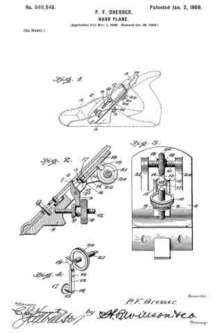
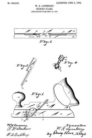
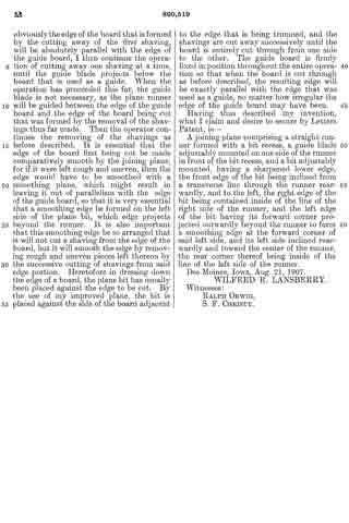
Figure 1 shows a side elevation of a joining plane embodying my invention. Fig. 2 shows an enlarged sectional view on the line 2–2 of Fig. 1, also showing two boards in position to be operated on by the plane, one of said boards formed with a cut such as would be made by the plane. Fig. 3 shows a perspective view of the plane bit detached, and Fig. 4 shows a perspective view of the bolt for clamping the bit to the plane.

Referring to the accompanying drawings, I have used the reference numeral 10 to indicate the body of the plane, provided with a handle 11 at its rear, and a handle 12 at its front. Below the body 11 is a smooth, straight runner 13, cut away at 14 to receive the bit. A groove is formed on the body portion 10 to receive the bit, which groove inclines downwardly and forwardly, terminating in the cut-away portion 14, and it also inclines rearwardly and toward the left of the plane body relative to a transverse line through the plane. This latter inclination may be readily seen in Fig. 2. The plane bit comprises a straight, flat body portion 15 designed to enter the groove in the plane body, and a shank 16 narrower than the part 15, and having its right edge arranged substantially flush with the right edge of the runner so that it will not cut into a board at the right side of the runner. The left edge ofthe shank 16 is arranged with the forward corner 18 thereof projected a slight distance outside of the line of the left side of the runner, and the rear corner lies inside of said line. That is to say, the left side of the bit inclines rearwardly and toward the center of the runner, thus leaving a smoothing edge 18 at the forward corner thereof that projects beyond the runner, and that serves as a smoothing blade for the edge of a board at the left side of the runner against which it is to be moved. The lower end of the bit is sharpened in the ordinary way to cut a shaving from a board over which it is moved. I have used the reference numeral 17 to indicate the right edge of the bit, and 18 the forward corner of the left edge, which is the smoothing center.

I have provided for adjustably securing the bit to the body by means of a bolt 19, having a flattened portion at 20, which bolt is inserted in a suitable opening in the body 10 with its flattened surface engaging the bit body 15, a winged nut 21 being provided on the other end of said bolt. Formed on the right side of the runner 13, in front of the cut-away portion 14 is a vertical groove 22, with a central slot 23 therein. Mounted in said groove is a guide blade 24, and a set screw 25 extends through the blade and through the slot 23, whereby the blade may be set to any position of its adjustment. This guide blade is on the side opposite from the smoothing edge of the bit.

In Fig. 2 of the drawings, I h ave shown the adjacent edge portions of two boards, one of which is to be trimmed down so that it will fit accurately to the other. The board to be trimmed is indicated by the numeral 26. The other board serves as a guide, and is indicated by the numeral 27.

In practical use, I first place the two boards that are to be joined, together on a bench, with the edges that are to be joined adjacent to each other, and as nearly parallel as possible, it being assumed that the boards do not have perfectly straight edges. I then select the board that has the straightest edge and use it as the guide, and proceed to cut away the edge of the other board. I do this by placing the plane in position with the guide blade 24 against the edge of the board that is to be used as a guide while the cutting edge of the bit rests on top of the board that is to be cut away, near its edge. I then cut away one shaving throughout the entire length of the board to be trimmed and obviously the edge of the board that is formed by the cutting away of the first shaving, will be absolutely parallel with the edge of the guide board, I then continue the operation of cutting away one shaving at a time, until the guide blade projects below the board that is used as a guide. When the operation has proceeded. this far, the guide blade is not necessary, as the plane runner will be guided between the edge of the guide board and the edge of the board being cut that was formed by the removal of the shavings thus far made. Then the operator continues the removing of the shavings as before described. It is essential that the edge of the board first being cut be made comparatively smooth by the joining plane, for if it were left rough and uneven, then the edge would have to be smoothed with a smoothing plane, which might result in leaving it out of parallelism with the edge of the guide board, so that it is very essential that a smoothing edge be formed on the left side of the plane bit, which edge projects beyond the runner. It is also important that this smoothing edge be so arranged that it will not cut a shaving from the edge of the board, but it will smooth the edge by removing rough and uneven pieces left thereon by the successive cutting of shavings from said edge portion. Heretofore in dressing down the edge of a board, the plane bit has usually been placed against the edge to be cut. By the use of my improved plane, the bit is placed against the side of the board adjacent to the edge that is being trimmed, and the shavings are cut away successively until the board is entirely cut through from one side to the other. The guide board is firmly fixed in position throughout the entire operation so that when the board is cut through as before described, the resulting edge will be exactly parallel with the edge that was used as a guide, no matter how irregular the edge of the guide board may have been.

Having thus described my invention, what I claim and desire to secure by Letters Patent, is —

A joining plane comprising a straight runner formed with a bit recess, a guide blade adjustably mounted on one side of the runner in front of the bit recess, and abit adjustably mounted, having a sharpened lower edge, the front edge of the bit being inclined from a transverse line through the runner rearwardly, and to the left, the right edge of the bit being contained inside of the line of the right side of the runner, and the left edge of the bit having its forward corner projected outwardly beyond the runner to form a smoothing edge at the forward corner of said left side, and its left side inclined rearwardly and toward the center of the runner, the rear corner thereof being inside of the line of the left side of the runner.

Des Moines, Iowa, Aug. 21, 1907.

WILFRED R. LANSBERRY.

Witnesses:
RALPH ORWIG,
S. F. CHRISTY.

No. 640,546 – Hand-Plane (Philo F. Dresser) (1900)

[paiddownloads id=”542″]640546


UNITED STATES PATENT OFFICE.

_________________

PHILO F. DRESSER, OF GLENWOOD, IOWA.

HAND-PLANE.

_________________

SPECIFICATION forming part of Letters Patent No. 640,546, dated January 2, 1900.
Application filed November 1, 1898. Serial No. 735,127. (No model.)

_________________

To all whom it may concern:

Be it known that I, PHILO F. DRESSER, a citizen of the United States, residing at Glenwood , in the county of Mills and State of Iowa, have invented certain new and useful Improvements in Hand-Planes; and I do declare the following to be a full, clear, and exact description of the invention, such as will enable others skilled in the art to which it appertains to make and use the same.

This invention relates to improvements in hand-planes and more particularly to that class in which the bit or plane-iron is both longitudinally and laterally adjustable; and the object is to provide a simple, inexpensive, and effective means for accomplishing this purpose; and a further object is to rigidly secure the bit in the position to which it has been adjusted, so as to prevent accidental displacement while in use.

To these ends the invention consists in the construction, combination, and arrangernent of the device, as will be hereinafter more fully described, and particularly pointed out in the claim.

In the accompanying drawings the same reference characters indicate the same parts of the invention.

Figure 1 is a perspective view of a plane embodying my invention, the stock and bit being shown in dotted lines, while the bed-piece and the mechanism for adjusting the bit are shown in full lines. Fig. 2 is a longitudinal section through the bit and bed-piece. Fig. 3 is a bottom plan view of the bed-piece. Fig. 4 is a perspective detail view of the lever-operating mechanisrn for laterally adjusting the bit.

1 denotes the stock; 2, the wedge-clamp ; 3, the plane-iron or bit, and 4 the bed-piece, which may form a part of or be rigidly fixed to the stock.

5 designates a lever fulcrumed in the bed-piece, its inner arm 6 extending into a recess 7 in the plane-iron, while its outer arm 8 is bifurcated to encompass the cylindrical shank 9 of the milled-head nut 10, adjustably mounted on the threaded stud 12, rigidly fixed in the bed-piece. It will be seen that by adjusting the milled-head nut 10 on the fixed stud 12 a longitudinal adjustment of the plane-iron is effected.

13 designates a lever fulcrumed on a stud 14, fixed in the lower face of the bed, and its shorter arm is formed with a lateral boss 15, carrying a pin 16, on the projecting end of which is journaled an antifriction-roller 17, which extends into the usual longitudinal slot 18 in the plane-iron. The opposite or longer end of the lever 13 is formed with two parallel lugs 19 19, extending in an opposite direction to the boss 15 to encompass the sides of the periphery of the milled nut 20, mounted on the transverse screw 21, rigidly fixed in the parallel brackets 22 22, formed integral with the bed-piece. It will thus be seen that a rotary movement of the nut 20 causes it to travel longitudinally on the fixed screw 21 and carry the free end of the lever 13 with it. This movement causes the inner end of the said lever to move in a correspondingly-opposite direction and carry the plane-iron with it, thereby providing for the lateral adjustment of the plane-iron.

I am aware that the plane-iron has heretofore been adjusted by rneans of a lever, but the free end of the lever projected beyond the upper end of the bed-piece for convenience of manipulation and in this exposed position was liable to accidental displacement, there being no means provided for locking the free end of the lever. In the present construction it will be observed that the nut 20 when not rotating acts as a lock for the outer end of the lever 13, and thereby prevents its movement in either direction.

The accompanying drawings show my invention in the best form now known to me, but many changes in the details might be made within the skill of a good mechanic without departing from the spirit of my invention as set forth in the claim at the end of this specification.

Having thus fully described my invention, what I claim as new and useful, and desire to secure by Letters Patent of the United States, is —

In a hand or bench plane having a laterally-adjustable plane-iron, the bed-piece 4 fined to the stock and the transverse screw 21 rigidly fixed thereto, the milled nut irremovably traversing said screw, the lever 13 fulcrumed on said bed-piece, with its upper end encompassing the contiguous edge of the milled nut, and the friction-roller 17 journaled on the lower end of said lever to engage the slotted plane-iron, substantially as and for the purpose set forth.

In testimony whereof I have hereunto set my hand in presence of two subscribing wltnesses.

PHILO F. DRESSER.

Witnesses:
L. S. ROBINSON.
H. T. RICHMOND.

No. 351,689 – Rabbet-Plane (William Henry Buswell) (1886)

[paiddownloads id=”416″]351689


UNITED STATES PATENT OFFICE.

_________________

WILLIAM HENRY BUSWELL, OF MANSON, IOWA.

RABBET-PLANE.

_________________

SPECIFICATION forming part of Letters Patent No. 351,689, dated October 26, 1886.
Application filed May 6, 1886. Serial No. 201,351. (No model.)

_________________

To all whom it may concern:

Be it known that I, WILLIAM HENRY BUSWELL, a citizen of the United States, residing at Manson, in the county of Calhoun and State of Iowa, have invented certain new and useful Improvements in Rabbet-Planes; and I do declare the following to be a full, clear, and exact description of the invention, such as will enable others skilled in the art to which it appertains to make and use the same, reference being had to the accompanying drawings, and to letters or figures of reference marked thereon, which form a part of this specification.

Figure 1 of the drawings is a representation of this invention, and is a top view. Fig. 2 is an end view. Fig. 3 is a detail, and is a vertical section through one of the cast-metal plates.

My invention relates to rabbet-planes designed for use in making rabbets of any desired depth and width in the material to be worked, without previously having to gage the rabbet or use a bevel-square; and the invention consists in the construction and novel combination of parts, as hereinafter described, and pointed out in the claim.

Referring by letter to the accompanying drawings, A designates the stock of the plane, which is provided with the bit-iron B, held in the stock by the wedge C, and the stock may be with or without a handle, according to the kind of plane-stock used. At its ends the stock A of the plane is provided with the cast-metal plates D and E, which plates are provided with longitudinal parallel slots F G, near their upper and lower edges, said slots extending nearly from end to end of said plates, the plates being beveled on their rear faces along the edges of the slots to form elongated countersinks, in which fit the heads H on the screw-stems I.

J J’ are rectangular plates secured to the enter faces of the slotted plates D E, said plates J J ‘ being held to their adjustments on the outer faces of the slotted plates D E by the screws I and thumb-nuts K K’.

L L’ are pivoted plates, secured to the rectangular sliding plates J J ’ by pivots M, passed through their lower inner corners. The pivoted plates L L’ are provided with arc slots N, in their cam-shape portions O, and from these cam-shape portions O project integral arms P, between which the gage-bar Q is secured by screws R R’, passed through holes in the arms P into the ends of the gage-bar Q.

By loosening the thumb-nuts K K’ the gage-bar can be moved in or out as far as the parallel slots will permit the slotted rectangular plates to slide.

By loosening the thumb nuts V V’ on the screws Y Y’, passed through the arc slots N, the gage-bar Q may be turned on its pivots, and be thereby caused to assume the required angle, after which the thumb-nuts V V’ may be tightened to hold the gage-bar at the angles to which it has been adjusted while the plane is being used. The upper edge of the gage-bar is beveled to fit the bottom of the plane and hold the gage-bar at the proper angle when said edge is moved under the stock of the plane.

Having described this invention, what I claim, and desire to secure by Letters Patent, is–

The improved rabbet-plane described, consisting of the stock A, the plates D E, having ing the parallel longitudinal slots and secured to the opposite ends of the stock in a plane relatively at right angles to the face thereof, the sliding rectangular plates J, held in sliding engagement with the said end plates by the transverse screws and nuts I K, the gage-bar, the plates R, having a semicircular slot, the thumb-nut working therein, an arm, P, for attachment to the ends of the said gage-bar, and their lower inner portions pivoted to a like point of the sliding end plates, substantially as specified.

In testimony whereof I affix my signature in presence of two witnesses.

WILLIAM HENRY BUSWELL.

Witnesses:
A. L. FUNK,
SOLOMON M. HEATH.

No. 303,338 – Bench-Plane (John F. Taber And William F. Gibbs) (1884)

[paiddownloads id=”369″]303338


UNITED STATES PATENT OFFICE.

_________________

JOHN F. TABER AND WILLIAM F. GIBBS, OF CLARION, IOWA.

BENCH-PLANE.

_________________

SPECIFICATION forming part of Letters Patent No. 303,338, dated August 12, 1884.
Application filed June 3, 1884. (No model.)

_________________

To all whom it may concern:

Be it known that we, JOHN F. TABER. and WILLIAM F. GIBBS, citizens of the United States, residing at Clarion, in the county of Wright and State of Iowa, have lnvented certain new and useful Improvements in Bench-Planes; and we do declare the following to be a full, clear, and exact description of the invention, such as will enable others skilled in the art to which it appertains to make and use the same, reference being had to the accompanying drawings, and to the letters and figures of reference marked thereon, which form a part of this specification.

The object of this improvement is a bench-plane with a reversible bearing-plate for either closing the throat of the plane, and thereby adapting it to cutting smoothly across the grain of the wood, or opening its throat, and thereby adapting it to ordinary service. These results are attained by the mechanism illustrated in the drawings herewith filed as part hereof, in which the same letters of reference denote the same parts in the different views.

Figure 1 is a sectional front elevation of a bench-plane embodying the features of our improvement. Fig. 2 is a sectional side elevation. Fig. 3 is a sectional view showing the throat of the plane open for ordinary planing. Fig. ft is a top view of the reversible plate. Fig. 5 is a transverse section of the same.

A is the plane-stock. B is the bit, of ordinary construction. C represents the usual wedge. The face of the plane is provided with a suitable recess, a, for the reception of a centrally-perforated reversible plate, D, having its opposite corners on one side cut away or converted, substantially as shown, and provided with recesses c c’ for the reception of the head E’ of the bolt E, which passes through the plane-stock A, and is provided at its upper end with a hand-nut, F, having a milled rim, f, and which screws down on the plane-stock, and rigidly secures the plate D in position. By adjusting the plate D with its flat side down or the corners d adjacent to the point of the bit B, the throat of the plane will be substantially closed, as shown in Fig. 2, and as the ordinary rising action of the shaving will thus be prevented, the bit will cut smoothly across the grain. By reversing the plate or turning its curved sides down, as shown in Fig. 3, the throat G will be opened, and the plane thus adapted for ordinary service.

Having explained the construction and operation of our improvement, what we claim, and desire to secure by Letters Patent, is —

The reversible plate D, having opposite convexed corners on one side, and recesses c c’ on opposite sides for the reception of the head E’ of the bolt E, in combination with the plane-stock A, leaving a recess, a, in the face or sole of the plane, forward of the bit, and immediately adjoining and continued into the throat G’ substantially as specified, for the purpose set forth.

In testimony whereof we affix our signatures in presence of two witnesses.

JOHN F. TABER.
WILLIAM F. GIBBS.

Witnesses:
C. F. PETERSON,
A. R. LADD.

No. 153,122 – Improvement In Planes (Leonard Shane) (1874)

[paiddownloads id=”231″]153122


UNITED STATES PATENT OFFICE.

_________________

LEONARD SHANE, OF HAMPTON, IOWA.

IMPROVEMENT IN PLANES.

_________________

Specification forming part of Letters Patent No. 153,122, dated July 14, 1874; application filed June 1, 1874.

_________________

To all whom it may concern:

Be it known that I, LEONARD SHANE, of Hampton, in the county of Franklin and in the State of Iowa, have invented certain new and useful Improvements in Planes; and do hereby declare that the following is full, clear, and exact description thereof, reference being had to the accompanying drawings and to the letters of reference thereon, making a part of this specification.

The nature of my invention consists in the use of a device which is secured to the end of a plane, for the purpose of canting the same, for planing beveled surfaces, as will be set forth.

ln the annexed drawings, Figure 1 is an end view of a plane with device attached, and Fig. 2 is a perspective of same. In the figures, A represents the end of a plane, to which is connected, by means of a set-screw, a slotted bar, B. To one end of this bar B is pivoted a triangular guide-plate, D; it is also connected to the bar B by means of a set-screw, i, which works through a slot, e, in said plate. The angle of the bar D can be changed on the end of the plane by means of the set-screw C, and the angle of the plate D can be changed on the bar B by means of its pivot and set-screw i. It will be seen that, by means of these two changes, the plane can be canted so that it will work upon irregular surfaces.

Having thus fully described my invention, what I claim as new, and desire to secure by Letters Patent, is —

The combination, with a plane, A, of the bar B, having the slot a, and the set-screw C, the triangular bar D, pivoted to the bar B, and having the curved slot e, and the adjusting-screw i, all substantially as and for the purposes set forth.

In testimony that I claim the foregoing, I have hereunto set my hand this 11th day of May, 1874.

LEONARD SHANE.

Witnesses:
J. W. McKENZIE,
G. C. HAYES.

No. 127,026 – Improvement In Bench-Planes (Morgan Chittenden) (1872)

[paiddownloads id=”195″]127026


UNITED STATES PATENT OFFICE.

_________________

MORGAN CHITTENDEN OF DANBUBY IOWA.

IMPROVEMENT IN BENCH-PLANES.

_________________

Specification forming part of Letters Patent No. 127,026, dated May 9, 1872.

_________________

SPECIFICATION.

I, MORGAN CHITTENDEN, of Danbury, in the county of Fairfield and State of Connecticut, have invented certain Improvements in Bench-Planes, of which the following is a specifcation:

The object of this invention is to attach to the stock of a common bench or other plane an adjustable and removable guide or fence that can assume any desired angle with relation to the f’ace of the plane; and it consists in the construction and arrangement of the devices necessary to so attach and adjust the fence or guide, as will hereinafter be fully described.

In the drawing, Figure 1 is a side view of a plane-stock guide, and the devices for clamping it to the stock, and adjusting it to different angles; Fig. 2 is an end view of same; Fig. 3 a side view of the clamp, and Fig. 4 a top sectional view of the same.

A represents the stock of the plane; B, the fence or guide. C is a portion of a clamp, by which the fence B is attached to the plane-stock by means of the strap-plate C’, that is made fast to the guide or fence, and is hinged to clamp-piece G at c”; on the lower end of clamp-piece C’ is a hook-like projection, c”’, that takes hold of the under or face side of the plane-stock, as seen in Figs. 2 and 3. D is a screw-rod, having a screw cut upon it a portion of its length from one end. E is a nut, fast on the screw-rod D, and by which the screw rod is turned. E’ is a swivel, having heads e’ e’ through which rod D freely turns, while on one side the connecting-bar has a holding~screw, e”, that holds the swivel fast upon the screw-rod at any desired point, on the opposite side of the swivel is plate f’. The swivel E’ is held to its place by collar e on one side and nut E on the other. F is a diagonal connecting-bar pivoted at f to plate f’, has a screw-swivel at f”, for the purpose of adjusting the length of the diagonal bar; and at the lower end of the screw-swivel is an eye that goes between ears f3 f3, and to which it is pivoted. G is a pivot-plate, pivoted to the outside of the fence or guide-piece B, and has cast upon it ears f3 f3, between which the swivel end of the diagonal connecting-rod or bar is pivoted, and by which the guide or fence is allowed to assume different positions with relation to the face of the plane. H is the upper part of the clamp, and has a hook. h, projecting from one side, and takes hold of the upper side of the plane-stock. This upper part of the clamp fits and slides into the lower and outer part C, and the two parts are held together only by screw h’ h’ is a screw, going longitudinally through clamp-piece H into clamp-piece C, and by turning up the screw brings the hooks h and c”’ nearer to each other, and consequently clamps the device fast upon the plane-stock. Screw-rod D freely slides and turns in a hole in a projecting rib on clamp part, G, at one ofthe clamps, as seen at c, while the screw part of the rod passes through a screw-nut in the other clamp-piece at c’.

The operation is as follows: After the device is clamped upon the plane-stock by turning screw h’ down hard, and thereby firmly securing the fence or guide to the stock by turning nut E, it will force the screw-rod D longitudinally in one direction or the other, carrying with it the upper end of the diagonal connecting-bar F, but by reason of the guide or fence B not moving longitudinally it is forced to turn on hinges c”, and turn outward, making an obtuse angle to the face of the plane; and by reversing the revolution of the nut E the rod D is forced in the reverse direction, and consequently the guide or fence B is pushed so as to form an acute angle to the face of the plane, thus making the fence conform to any angle desired, when it is held firmly in such angle by screw e”.

By this construction the fence or guide can be attached to and removed from any plane-stock without marring or defacing it, and saving much in the expense of having extra planes with the fence attached, as this can be made to be put upon or attached to any plane.

I claim as my invention —

1. The sliding-rod D, diagonal bar F, plate G, and guide or fence B hinged to clamps C C H H, in combination with the plane-stock A, constructed to operate as shown and described.

2. The combination of the parts C of the clamps, straps C’ hinged thereto, screw-rod D, turning-nut E, swivel E’, bar F and plate G with the fence or guide B, constructed to operate substantially as herein described.

3. Attaching the removable and adjustable fence or guide B to the plane-stock A, by means of the clamps formed of parts C, to which the guide is hinged, and H having hooks c”’ and h, and holding-screw h’, in the manner herein described.

MORGAN CHITTENDEN.

Witnesses:
DAVID B. BOODY,
ALFRED BELL.

No. 107,765 – Improvement In Splint-Planes (Philander N. Drake And David Drummond) (1870)

[paiddownloads id=”160″]107765


United States Patent Office.


PHILANDER N. DRAKE AND DAVID DRUMMOND, OF MCGREGOR, IOWA.

Letters Patent No. 107,765, dated September 27, 1870.
_________________

IMPROVEMENT IN SPLINT-PLANES.

_________________

The Schedule referred to in these Letters Patent and making part of the same.

_________________

To all whom it may concern:

Be it known that we, PHILANDER N. DRAKE and DAVID DRUMMOND, of McGregor, in the county of Clayton and in the State of Iowa, have invented certain new and useful Improvements in Splint-Plane or Slat-Cutter; and do hereby declare that the following is a full, clear, and exact description thereof, reference being had to the accompanying drawing and to the letters of reference marked thereon, making a part of this specification.

Our invention relates to that kind of planes used in cutting thin strips or slats for rustic shades, and other purposes, and consists —

First, in placing the cutter under the bottom of the plane, level with the edge of the board from which the strips or slats are to be cut;

Second, in the construction of the mechanism for holding the cutter in its place; and

Third, in the construction of the mechanism for regulating the thickness of the strips or slats to be cut.

In order to enable others skilled in the art to which our invention appertains to make and use the same, we will now proceed to describe its construction and operation, referring to the annexed drawing, in which —

Figure 1 is a side view, part in section, of our plane;
Figure 2 is a transverse vertical section; and
Figure 3, a bottom view of the same.
Figure 4 shows the end of the cutter, with the channel-plates in the plane.

A represents the body of our plane provided with a handle, B.

Along one side of the body A is secured a bar, C, projecting below the plane a suitable distance to form a guard or guide for the tool.

Between the under side of the plane A and the bar C is formed a groove, in which the inner edge of the cutter D is inserted, said cutter being laid level under the lower side, or against the lower side of the plane A.

The cutting-tool D is held by means of a stirrup, E, constructed as shown in fig. 2, and passed up through the plane A, with a screw-shank at its upper end, which projects above the plane.

On this screw-shank is placed a thumb-nut, G, by means of which the stirrup is raised so as to firmly bind the cutting-tool. The pitch of the cutting-edge of said tool is regulated by means of two inclined screws, I I, passing through the plane A and bearing against the upper surface of the cutter, one on each side in front of the stirrup E.

The tool-bit being on a level with the edge of the board, it splits with less liability to break the fiber on the back of the slat. When it is to be taken out to sharpen, it can be put back to its place accurately and cut all the work of uniform thickness.

The two screws, I I, forcing the cutting-edge of the cutter to the desired position for uniform thickness, may, of course, remain in the same position for any length of time without change, even though the cutter is taken out and replaced again.

In the channel on the under side of the plane A, between it and the cutter D, are placed three channel-plates, a, b, and d, the relative positions of which are plainly indicated in fig. 4. The object of these plates is to further enable us to vary the thickness, if we desire to do so.

The back or upper side ofthese plates may be provided with inclines to enable them to be pushed forward or back.

The middle plate d is made so that it can readily be taken out and another of different size substituted.

Having thus fully described our invention,

What we claim as new, and desire to secure by Letters Patent, is —

The combination, with the stock A, of the flat-laid tool D, channel-plates a b d, stirrnp E, nut G, and screws I I, all constructed to operate substantially as set forth.

In testimony that we claim the foregoing, we have hereunto set our hand and seals this 26th day of March 1870.

PHILANDER N. DRAKE. [L. S.] DAVID DRUMMOND. [L. S.]

Witnesses:
A. J. JORDAN,
ORLANDO McCRAREY.

No. 67,157 – Improvement In Planes For Cutting Blind-Slats (James L. Bess And Adam Hagny) (1867)

[paiddownloads id=”129″]67157


United States Patent Office.


JAMES L. BESS AND ADAM HAGNY, OF KEOKUK, IOWA.

Letters Patent No. 67,157, dated July 30, 1867.
_________________

IMPROVEMENT IN PLANES FOR CUTTING BLIND-SLATS.

_________________

The Schedule referred to in these Letters Patent and making part of the same.

_________________

TO ALL WHOM IT MAY CONCERN:

Be it known that we, JAMES L. BESS and ADAM HAGNY, of Keokuk, in the county of Lee, and State of Iowa, have invented a new and useful Improvement in Planes for Cutting Blind-Slats; and we do hereby declare the following to be a full, clear, and exact description of the nature, construction, and operation of the same, reference being had to the accompanying drawings, which are made a part of this specification, and in which —

Figure 1 is a perspective view of our improved plane, showing the some in its operating position.

Figure 2 is an under side perspective view of the same.

Similar letters of reference indicate corresponding parts in the two figures.

The subject of our invention is a hand-plane adapted to out two or more thin slats for window-shades, blinds, &c., at every stroke or movement, and at the same time dress or prepare the material for the operation.

The following description will enable others skilled in the art to which my invention appertains to fully understand and use the same:

A A1 represent the body of the plane, which is formed with a guide-way or gauge groove, B, which embraces the edge of the plank from which the slats are out when the plane is in operation. The material or plank is clamped immovably, and the plane is driven over its edge by means of the handle A2, in the same manner as an ordinary smoothing-plane. C is a bit or cutter extending across the gauge-groove B, and this cutter, when the plane is in operation, cuts from the material or plank a strip of sufficient thickness to form the slats. A suitable throat, c, is formed between the bottom of the plane and the cutter C to make room for the slats as they are cut from the stuff. The sides of the plank are dressed by the knives D D, situated at either side of the groove B, and secured in position by keys D’ D’. Before reaching the cutter C that portion of the wood which is removed by each stroke of the plane is divided longitudinally by the pointed, perpendicular knives E E E’, and by this means two slats are produced by every effective movement of the plane. The outer knives E E are secured in position and made adjustable by the screws F F, which enter the plane from opposite directions, as shown in fig. 1, but for convenience, the central knife E’ is held and made adjustable by means of the key F’. The two parts of the plane A A1 are held together by means of the screws G G, which enable said parts to be adjusted from or toward each other, and thus vary the width of the gauge-groove according to the thickness of the material, or in order to vary the width of the slats. The cutter C passes through slots in tho sides of the plane, and is retained in proper working position by the jaws H H’, which are slotted and held to the opposite sides of the plane by the screws h h. By means of these jaws the knife C may be adjusted so as to cut slats of any desired thickness. The slotted end of the bit or cutter C is held to the jaw H’ by the screw h’, which admits of the lateral adjustment of the jaw upon the bit when the plane is increased or diminished in width by the screws G G.

Having thus described my invention, the following is what we claim as new herein, and desire to secure by Letters Patent:

The arrangement of the slitting cutters E E E’, edge-cutters D D, and riving-cutter C in a frame A A’, expansible by means of set-screws G’ G, all as herein described and for the purpose specified.

JAMES L. BESS,
ADAM HAGNY.

Witnesses:
DAVID G. LOWRY,
SAM. H. DILLON.

No. 41,317 – Improvement In Planes (Eli Odell) (1864)

[paiddownloads id=”101″]41317


UNITED STATES PATENT OFFICE.

_________________

ELI ODELL, OF WINTERSET, IOWA.

IMPROVEMENT IN PLANES.

_________________

Specification forming part of Letters Patent No. 41,317, dated January 19, 1864.

_________________

To all whom it may concern:

Be it known that I, ELI ODELL, of Winterset, Madison county, and State of Iowa, have invented an Improvement on the Common Plane in two particulars, as hereinafter described, reference being had to the accompanying drawings, and to the letters of reference marked thereon.

The nature of my improvements are in the two following particulars: First, the thread of the plane is to be cut concave, instead of convex, as in the usual term, thus entirely preventing it from choking with shavings, as is customary with the common form; second, improvement is to prevent the enlargement of the throat of plane as the face wears away by use, which is done in the following manner: Cut out to the depth of one inch (more or less) the face of the plane from the throat to the iront end. Then cut a groove in the center of the plane from the front end to the throat on the under side. Then make a separate piece to form that part of the face of the plane cut out, and also to fit the groove accurately. The object of this piece on the face of the plane is to keep the throat of the plane small as the face wears away by use, and is done by cutting the shoulder at the throat of the plane and sliding the face-piece toward the bit, and is represented by the letter B. Thus, the throat may be regulated in size until the plane is worn out. Said face-piece is moved by and held by two screws, the one on the top, letter C, passing through the upper part of the plane and down into letter B into a nut that has play, that it can slide along in a mortise in letter B. The other, in the frontend, (represented by D,) connects with a nut in a mortise in the upper part of the plane, which nut hooks into letter B, which can slide either to open or shut the throat. In order to disconnect letter B (the face-piece) from the plane, unscrew letter C until letter B comes loose.

What I claim as new, and desire to secure by Letters Patent, is —

A plane, with the adjustable face-plate B, in combination with a concave throat, the whole constructed and operated substantially as described.

ELI ODELL.

Witnesses:
JNO. LEONARD,
A. D. NOSLER.

No. 53,899 – Planes For Making Blind Slats (Enoch K. Thomas And Hans H. Andresen) (1866)

[paiddownloads id=”116″]53899


UNITED STATES PATENT OFFICE.

_________________

ENOCH K. THOMAS, OF ROCK ISLAND, ILLINOIS, AND HANS H. ANDRESEN, OF DAVENPORT, IOWA.

IMPROVEMENT IN PLANES FOR MAKING BLIND-SLATS.

_________________

Specification forming part of Letters Patent No. 53,899, dated April 10, 1866.

_________________

To all whom it may concern:

Be it known that I, ENOCH K. THOMAS, of Rock Island, Rock Island county, and State of Illinois, and HANS HEINRICH ANDRESEN, of Davenport, Scott county, State of Iowa, have invented a new and useful Plane for Making Window-Shade Slats; and we do hereby declare that the following is a full, clear, and exact description thereof, reference being had to the accompanying drawings, making a part of this specification, in which —

Figure 1 is a perspective view of a single-iron slat-plane. Fig. 2 is a perspective view of the cutter or plane-iron detached from the plane-stock. Fig. 3 is a sectional view, showing the mode of cutting slats from a piece of wood. Fig. 4 is a front end view of the single iron plane. Fig. 5 is a front end view of a plane-stock which is adapted for receiving three cutters.

Similar letters of reference indicate corresponding parts in the several figures.

The object of this invention is to produce slats for wooden window-shades of a uniform thickness and width by means of a plane which is so constructed that the slats pass freely through the plane-iron between the sole of the plane-stock and its bottom cutter without liability of becoming broken or otherwise injured, as will be hereinafter described.

To enable others skilled in the art to understand Our invention, we will describe its construction and operation.

The plane which we have represented in Figs. 1, 2, 3, and 4 of the drawings is intended for cutting one slat at a time from a piece of wood. The sole of this plane has three steps, a a’ a”. The intermediate step, a, is equal in width to the width of the slats which are produced, and the vertical surface of the step a2 is intended to form a side guide for the plane-stock in its forward movements over the piece of wood from which the strips or slats are cut.

The cutter or plane-iron B has a cutting-lip, b, on its lower end and a cutting-lip, c, formed on one side — that side which is nearest the step a. This plane-iron has an opening, d, through it, which should be equal in width to the width of the slats that are cut, so that as the slats that are severed from the piece of wood by the horizontal and vertical cutting-lips b c these slats will pass freely through the plane-iron without being materially bent out of a straight line, as shown in Fig. 3.

The plane-iron B is secured at the required pitch in its stock A by means of a wedge, C, in the usual manner of securing common plane-irons into their stocks, and the cutting-lip b projects below the sole of the stock a distance which is equal to the thickness desired for the slats.

It will be necessary to form a depression, e, just in rear of the cutter lf, so as to allow of the slats rising over this cutter; but as this cutter can be made quite thin, it will not be necessary to form much of a depression in the sole of the stock.

To obviate a gouging action of the cutting-lip b, which would cause the plane to work very hard and produce slats of an uniform thickness, the space between the cutting-edge of said lip and the lower end of the wedge C should not be greater than the required thickness ofthe slats. The space back of this point for a short distance may be increased, as above mentioned.

It will be seen from the above description of our plane or slat-cutter that the slat is held firmly down upon the surface of the piece of wood during the operation of producing it, and that the only elevation of the slat from such surface takes place at the cutter b, which must pass under the slat; but while this is the case the slat which is being cut will he held down in rear of said cutter, so that it cannot be broken or split.

We do not confine our invention to a single-iron plane for cutting or producing slats, as the stock may be adapted for receiving two, three, or more cutters, arranged as shown in Fig. 5, so that a number of slats can be cut at each forward movement of the plane over the piece of stuff.

It is obvious that this plane may be secured to a bench-vise or to any other object and the stuff moved over it instead of moving the plane by hand over the fixed stuff ; or, if desirable, the plane or the stuff from which the slats are cut may be moved by machinery without changing the principle of our invention. One great advantage of our invention is that we can cut slats from the side or edge of a board or log without the necessity of resawing and previously dressing the stuff, and this can be done with stuff of any thickness or width.

Were not our cutter provided with the two cutting-edges described, the splints or slats could not be cut from a bolt or plank of a greater thickness than the length of the cutting-edge of the cutter or plane-iron. This will be evident from an inspection of the drawings illustrating our mode of cutting strips or splints from a large bolt or log.

By arranging a series of cutters on a plane-stock, stepped as shown, we can, after having cut a series of splints from the bolt, bring two cutters into use, and after we have cut another series of splints by each of the two cutters we can bring into use a third cutter in connection with the two which are already brought into use, and so on, according to the number of steps and cutters provided on the plane-stock. To bring the different cutters into use a channel in the wood must be made tbr a succeeding cutter by a preceding cutter, as must be evident. Thus by our invention a series of splints may be cut at one time from a bolt which is of much greater thickness than the length of the edge of either of the cutters after channels adapted for the respective cutters are cut in the bolt.

Having thus described our invention, what we claim as new, and desire to secure by Letters Patent, is —

1. The construction of a cutter for producing slats with two cutting-edges and an opening through the shank of the cutter for the passage ofthe slats, substantially as described.

2. The combination of one or more slat-cutters, constructed substantially as described, with a plane-stock having its sole stepped substantially as set forth.

ENOCH K. THOMAS.
HANS HEINRICH ANDRESEN.

Witnesses:
HANS ARBAHR,
HANS KÜHAER.