No. 869,267 – Plane (John H. Shaw) (1907)

[paiddownloads id=”650″]869267


UNITED STATES PATENT OFFICE.

_________________

JOHN H. SHAW, OF NEW HAVEN, CONNECTICUT, ASSIGNOR TO SARGENT & COMPANY, OF NEW HAVEN, CONNECTICUT, A CORPORATION OF CONNECTICUT.

PLANE.

_________________

869,267. Specification of Letters Patent. Patented Oct. 29, 1907.
Application filed August 10, 1905. Serial No. 273,590.

_________________

To all whom it may concern:

Be it known that I, JOHN H. SHAW, of the city and county of New Haven, State of Connecticut, have invented new and useful Improvements in Planes, of which the following is a full, clear, and exact description, when taken in connection with the accompanying drawings, which form a part thereof, and in which —

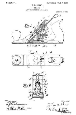
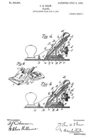
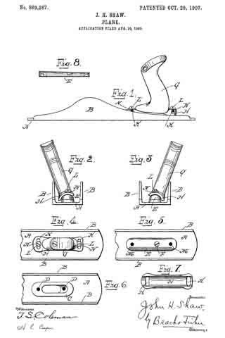
Figure 1 represents a side elevation of a plane embodying the invention, Fig. 2 an end view of the same, Fig. 3 a similar view with the handle shown adjusted to a different position, Fig. 4 a top view of the handle end of the plane, Fig. 5 a similar view with the handle removed, Fig. 6 a similar view with the supporting block removed, Fig. 7 a bottom view of the handle plate, and Fig. 8 a side elevation of the supporting block.

In all figures, similar letters of reference represent like parts.

This invention relates to planes, and has for its object the production of a simple and efiicient construction by which the handle may be adjusted so that the plane can be used close to a wall or other object without injury to the hand of the operator.

When a plane is used in proximity to an object, as a wall, it is diflicult to bring the plane close to the corner without interfering with the hand of the operator. To this end various methods have been devised by which the handle may be adjusted or turned to an angle other than a right angle to the bottom of the plane so as to remove the hand of the operator further from the side of the plane against the wall.

The present invention consists of a removable supporting block for the handle, which may be mounted on the ordinary plane body so that the handle may be adjusted or rotated on the supporting block to project at the desired angle, together with other improvements and combinations of parts hereinafter described and claimed.

For a better understanding of the invention reference is had to the accompanying drawings, in which the parts designated by the letter A represent the plane body and B the sides thereof. On the plane body, near the rear, is a usual base C for the handle, having a screw hole or holes D. When a handle is mounted on this base it assumes the ordinary position at right angles to the plane body, and is incapable of adjustment.

A supporting block E is therefore provided, which is herein shown fiat on its under side and convex transversely on its upper face (Figs. 2 and 3). The supporting block E is adapted to be secured to the plane body by a screw F, or other means, taking into one of the screw holes D.

The handle G is provided at its lower end with a plate H concaved transversely as shown, so that its under face is adapted to fit on the convex surface of the supporting block E. The plate is provided with one or more transverse slots K for the reception of screws L, which extend through the slots and take into screw holes M in the block E. The heads of the screws L or washers N, engaged thereby, bear on the plate H to bind in its adjusted position.

To shift the handle from one angle with the plane body to another it is only necessary to unscrew the screws L and the plate H will then be capable of sliding in either direction on the block E, so that the handle will assume either of the positions indicated in Figs. 2 or 3. When the screws L are tightened the handle is secured to its adjusted position. As the block E is removable the plane body may be used with an adjustable handle or with an ordinary handle as desired.

Having now described my invention, what I claim and desire to secure by Letters Patent is:

In a plane, the combination with the plane body; of a removable supporting block curved in cross section and adapted to be rigidly secured to the plane body; a correspondingly curved plate adapted to fit on said supporting block; a handle secured to said plate; slots in said plate; and screws projecting through said slots and engaging said block to hold said plate and handle in their adjusted position, substantially as described.

In witness whereof, I have hereunto set my hand on the 4th day of August, 1905.

JOHN H. SHAW.

Witnesses:
W. A. RICE,
L. F. BREESE.

No. 824,954 – Plane (John H. Shaw) (1906)

[paiddownloads id=”633″]824954


UNITED STATES PATENT OFFICE.

_________________

JOHN H. SHAW, OF NEW HAVEN, CONNECTICUT, ASSIGNOR TO SARGENT AND COMPANY,
OF NEW HAVEN, CONNECTICUT, A CORPORATION OF CONNECTICUT.

PLANE.

_________________

824,954. Specification of Letters Patent. Patented July 3, 1906.
Application filed April 17, 1903. Serial No. 153,092.

_________________

To all whom it may concern:

Be it known that I, JOHN H. SHAW, of the city and county of New Haven, State of Connecticut, have invented new and useful Improvements in Planes, of which the following is a full, clear, and exact description when taken in connection with the accompanying drawings, which form a part thereof, and in which —

Figure 1 represents a central vertical section, the ends being shown in elevation, of a plane embodying my invention; Fig. 2, a plan view of the bed of the plane; Fig. 3, a vertical transverse section on lines 3 3 of Fig. 1; Fig. 4, a longitudinal vertical section on lines 4 4 of Fig. 3 of a portion of the plane; Fig. 5, a similar view, the bit being shown in a different adjustment; and Fig. 6 is a perspective view of the support E.

In all figures similar letters of reference represent like parts.

This invention relates to planes, and has for its object the production of a plane in which the frog may be adjusted longitudinally and clamped in place after the bit is clamped to the frog.

in the proper adjustment of the bit of a plane it is necessary to move the bit longitudinally on the frog, so that the cutting edge will project more or less through the throat of the frame according to the depth of the cut desired. When properly adjusted, it is necessary in order that the bit may be held firmly in place that its cutting end should rest against the rear of the throat and against the frog. Owing to the variations in the angle to which the bit is ground, the adjustment of the bit longitudinally on the frog may affect its position in the throat and against the frog. It is an important desideraturn, therefore, in order to prevent what is known as “chattering,” which occurs when the lower end of the bit is not held firmly against the throat and frog, that the frog may be adjusted on the frame after the bit is adjusted longitudinally on it, because were it necessary to remove the bit in order to adjust the frog a number of attempts might be required to establish the exact relation between the frog and throat and beveled end of the bit.

To this end my invention resides in the production of a novel construction by which the adjustment of the frog may be made from the rear after the bit is secured to the front face of the frog, as set forth and claimed hereinafter, together with other minor improvements.

Referring to the drawings for a more particular description, the parts designated by the letter A represent the frame or stock of the plane, and a the throat thereof, which extends transversely across the bottom.

B is a raised portion near the middle of the frame having screw-holes b and a vertical flange b’ at right angles to the plane, provided with a substantially semicircular groove b2.

C’ represents the bit or plane iron, to which is secured b the screw c the cap-iron D. The forward end d of the cap-iron D is bowed outward in well-known manner.

E is a frog or support for the bit adapted to rest on the raised portion B of the frame A and having a depending portion e, adapted to rest on the frame A immediately in the rear of the throat a.

F is a screw projecting from the front of the support E, the head of which is adapted to engage and hold in place the clamping-cap G. The forward end of the clamping-cap G bears on the bowed portion d of the cap-iron D, and pivoted to the rear end of the clamping-cap is a cam-clamp H, adapted to bear on a spring-plate it to lock the cap in place between the engaging head of the screw F and the cap-iron D.

I designates a set-screw secured to said support and on which is mounted a nut J, having an annular groove j, engaged by the forked end k of a bell-crank lever K, plivoted at k’ to the support, and having its other end k2 engage the cap-iron D in well-known manner. By means of the nut J and lever K the cap-iron D and the bit C, secured thereto, are adjusted longitudinally on the forward inclined face of the support E.

L is a lever pivoted to the support at l, adapted to engage the screw c, connecting the bit C and cap-iron D. By means of the lever L the bit may be adjusted transversely in well-known manner.

M is an adjusting-screw adapted to be screwed into the rear of the support and having on its head an annular groove m, adapted to be engaged by a flange b’ on the frame of the plane. The support E has lateral projecting portions e’ upon its respective sides and preferably extending to the rear of the body portion thereof, and e” designates upright arms on said projecting portions connecting with the body portion.

O designates one or more clamping-screws adapted to extend through longitudinal slots P in the projecting portions of the support and engage in internally-threaded screw-holes b in the frame.

By this construction it is possible to adjust and clamp the support in place after the bit is properly mounted on the support, for after the bit is so mounted the clamping-screws O may be loosened and the support moved forward or backward by the adjusting-screw M.

Having now described my invention, what I claim, and desire to secure by Letters Patent, is —

1. In a plane, the combination with a frame, of a bit, a throat in said frame throihgh which said bit may project, a longitudinally-adjustable frog or support carrying the bit-adjusting means, a part carried by the support and projecting rearwardly of the bit-adjusting means, an clamping means for retaining the support in adjusted position, said clamping means being arranged to engage said projecting part of the support at a spaced distance from the body part thereof, whereby it is accessible when the bit is mounted on the support.

2. In a plane, the combination with a frame, of a bit, a throat in said frame through which said bit may project, a bodily-adjusting means, and means for clamping said support in its adjusted position carried by a rearwardly-projecting portion of the frog and accessible when the bit is mounted on said support.

3. In a plane, the combination with a frame, of a bit, a throat in said frame through which the bit may project, a movable support on said frame to the rear of said throat and carrying the bit-adjusting means, an adjusting-screw for adjusting said support longitudinally of said frame from the rear of said support, and a clamping screw or screws adapted to hold said support in its adjusted position, said screw or screws being carried by a rearwardly-projecting part of the support and accessible when said bit is in place on said support.

4. In a plane, the combination with a frame having a portion substanially parallel to the bottom thereof, of a bit, a throat in said plane through which the bit may project, a support carrying the bit-adjusting means on said frame capable of moving longitudinally on said parallel portion of said frame, a slot in a rearwardly-projecting portion of said support, and a clamping-screw passing through said slot into said frame to hold the support from movement on said frame, whereby said clamping-screw is accessible for mampulation while said bit is in place on said support.

In witness whereof I have hereunto set my hand on the 28th day of February, 1903.

JOHN H. SHAW.

Witnesses:
LE ROY J. KIRKHAM,
ALICE A. WILSON.

No. 377,645 – Bench-Plane (John H. Shaw) (1888)

[paiddownloads id=”427″]377645


UNITED STATES PATENT OFFICE.

_________________

JOHN H. SHAW, OF NEW HAVEN, CONNECTICUT, ASSIGNOR TO
SARGENT & COMPANY, OF SAME PLACE.

BENCH-PLANE.

_________________

SPECIFICATION forming part of Letters Patent No. 377,645, dated February 7, 1888.
Application filed July 5, 1887. Serial No. 243,353. (No model.)

_________________

To all whom it may concern:

Be it known that I, JOHN H. SHAW, of New Haven, in the county of New Haven and State of Connecticut, have invented a new Improvement in Planes; and I do hereby declare the following, when taken in connection with accompanying drawings and the letters of reference marked thereon, to be a full, clear, and exact description of the same, and which said drawings constitute part of this specification, and represent, in —

Figure 1, a side view of the plane complete; Fig. 2, a face view of the plane-iron bed, showing the transverse adjusting-screw; Fig. 3, a back side view of the plane-iron; Fig. 4, a vertical section through the transverse adjusting-screw and in the slot of the plane-iron; Fig. 5, a modification in the support of the transverse adjusting-screw.

This invention relates to an improvement in that class of planes in which the stock is made from metal, and is provided with means for adjusting the plane-iron to give a greater or less cut. Usually the only adjustment made by the mechanism of the plane itself is to produce a greater or less extent of cut by the plane-iron; but in setting the plane-iron a lateral adjustment is necessary. This is generally produced by means of a hammer striking the edge of the plane-iron to turn it to the right or left, as the case may be, to bring it into proper relation to the face of the plane. A device has been applied to the plane by which the lateral adjustment may be produced mechanically, this device consisting of a lever hung upon the stock and engaged with the iron, so that by turning the lever to one side or the other the plane-iron will be thrown accordingly; but this adjustment is liable to displacement by accidental blows upon the lever, and is not capable of that nice adjustment which is necessary in setting the iron, and is inconvenient in many respects. In another case an endless screw has been transversely arranged across the stock of the plane, and in engagement with the same lever by which the cut of the plane is adjusted; but in this construction the adjustment by one screw is liable to be deranged by the adjustment of the other screw, because of both screws acting in different directions upon the same lever.

The object of my invention is to apply a screw for the transverse adjustment of the iron, but independent of the cut-adjusting device, whereby the nicest adjustment may be produced without liability of accidental displacement.

A represents the stock, which may be any of the usual or known constructions, and in which the plane-iron B is arranged in the usual manner and secured by any suitable device.

C represents the adjusting-screw by which the plane-iron is adjusted to produce a greater or less cut — a common and well-known device, and does not require particular description. The stock is provided with a solid bed, D, upon which the plane-iron rests, also in the usual manner. In the stock, above the point where the adjusting device engages the plane-iron, (E representing the opening in the bed through which the adjusting device engages the iron,) I arrange a transverse screw, F, there being a transverse recess, G, formed across the bed for this purpose. In the recess in the bed one or more bearings, a, are formed for the screw, the seats in these bearings being of less diameter than the body of the screw. The screw itself is constructed with annular grooves b, corresponding to the bearings a, and so that laid into the bearings, as indicated in Fig. 2, the screw may rotate in the bearings, but held by the bearings against movement in an axial direction.

The outer end of the screw is provided with a suitable head, H, by which it may be turned. On the screw is a nut, I, adapted to slide through the recess in which the screw is applied, the nut being internally screw-threaded corresponding to the thread of the screw, and because the nut can not revolve in the recess, owing to its shape, as seen in Fig. 4, it follows that the rotation of the screw will impart to the nut a transverse movement, according to the direction in which the screw is turned. The nut projects above the face or bearing-surface of the bed and enters the slot J in the plane-iron B, the length of the nut corresponding to the width of the slot, the slot being of a standard width in all irons adapted to a certain size plane.

When the plane-iron is secured in the stock in the usual manner, if it be desired to impart transverse movement to the iron in either direction, the screw H is turned accordingly, and through the nut I imparts such required transverse movement to the plane-iron, and when once set there is no liability of accidental dis-adjustment, and the most perfect adjustment may be made by the screw, much more so than can be produced by a lever which is turned by hand or by blows imparted to it.

The bearings a in the recess in the bed are equidistant from the center, so that the screw may be introduced with its head either to the right or left, as indicated in Fig. 2, solid lines indicating the left-hand position and broken lines the right-hand position. The bearings are simply of U shape, open outward, as seen in Fig.2, so that the screw may be dropped therein. The adjusting device is therefore readily removable from the plane should occasion require.

It will be understood that the transverse adjustment may be applied to a plane with any of the many different vertical adjustments, or without vertical adjustment should it be desired.

While I prefer to construct the recess with the bearings a, into which the screw may be dropped or readily removed, as I have described, it may be supported permanently in the recess, as seen in Fig. 5, it only being essential that when the screw is in its place it shall be prevented from movement in an axial direction, yet left free for rotation, and carry the nut.

From the foregoing it will be understood that I do not claim, broadly, the combination, in a plane, of a transverse or lateral adjusting-screw for the plane-iron.

I claim —

In a plane substantially such as described, the bed upon which the plane-iron rests, constructed with a transverse recess, G, and with one or more bearings, a, therein, combined with a screw, F, constructed with annular groove or grooves corresponding to said bearing or bearings and adapted to set therein, the said screw provided with a head upon its outer end, by which it may be rotated, a nut, I, in said recess and upon said screw, but independent of the cut-adjusting mechanism, the said nut adapted to engage the plane-iron, substantially as and for the purpose described.

JOHN H. SHAW.

Witnesses:
OTTO SCHLIEPER,
CHAS. L. BALDWIN.