No. 842,275 – Scraper (Justus A. Traut) (1907)


UNITED STATES PATENT OFFICE.
_________________
JUSTUS A. TRAUT, OF NEW BRITAIN, CONNECTICUT, ASSIGNOR TO STANLEY RULE & LEVEL COMPANY,
OF NEW BRITAIN, CONNECTICUT, A CORPORATION OF CONNECTICUT.
SCRAPER.
_________________
842,275. Specification of Letters Patent. Patented Jan. 29, 1907.
Application filed March 8, 1906. Serial No. 304,937.
_________________
To all whom it may concern:
Be it known that I, JUSTUS A. TRAUT, a citizen of the United States, residing at New Britain, Hartford county, Connecticut, have invented certain new and useful Improvements in Scrapers, of which the following is a full, clear, and exact description.
My invention relates to improvements in scrapers.
The object is to facilitate adjustment of the parts and improve the construction so that it may be adapted to use under many different circumstances. I have sought to construct the parts so that they may be manufactured readily and assembled or taken apart without difficulty.
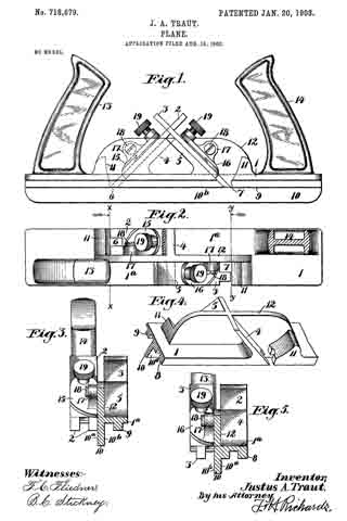
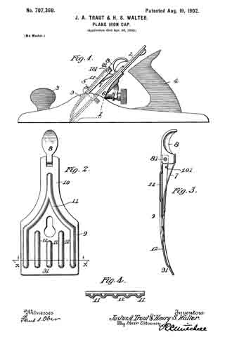
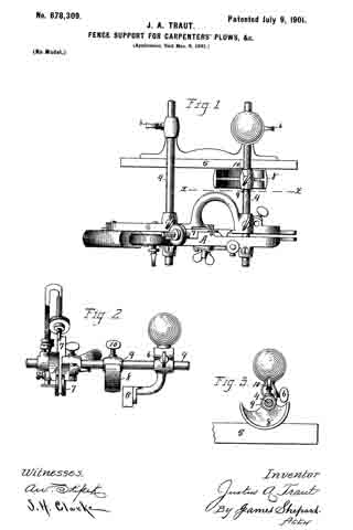
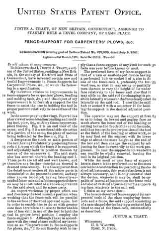
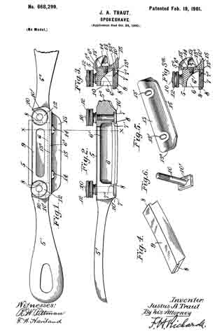
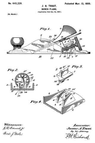
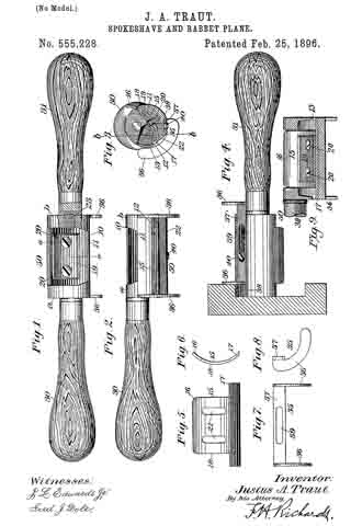
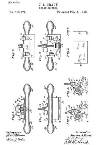
The preferred form of the invention is shown in the accompanying single sheet of drawings, in which —
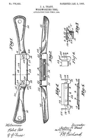
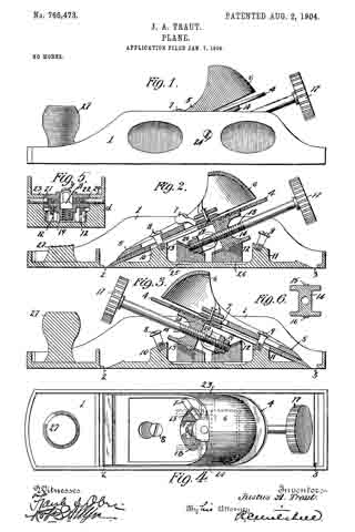
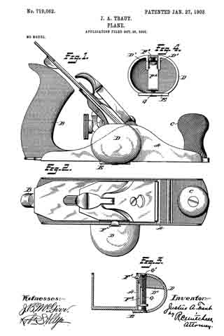
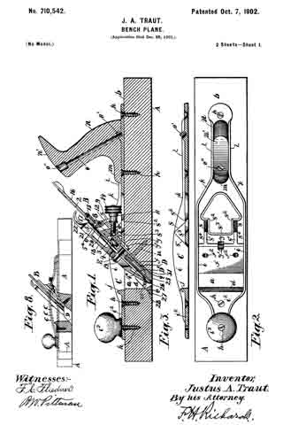
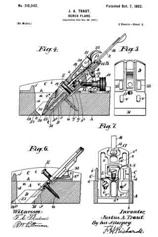
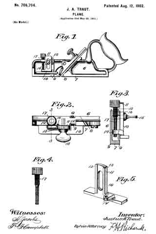
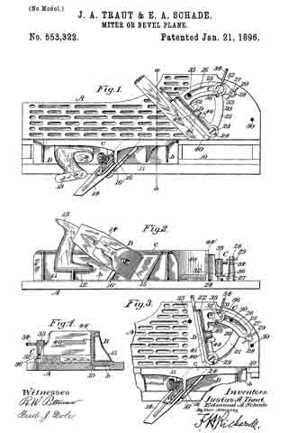
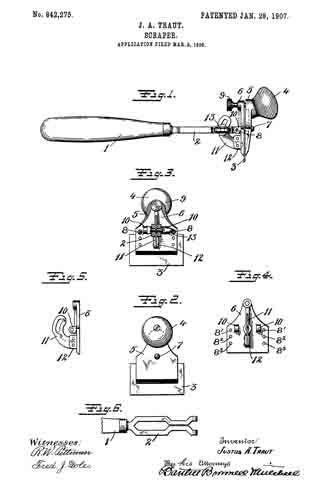
Figure 1 is a side view of the scraper embodying the improvements of my invention. Fig. 2 is a front view of the same. Fig. 3 is a rear view of the scraper with the handle shown in section. Fig. 4 is a rear view of the back member of the head. Fig. 5 is a side view of the same. Fig. 6 is a plar view of a fragment of the handle.
The handle is preferably formed in two portions — a grip member 1 and a body member 2.
The head of the scraper carries the blade 3 and is preferably provided with an auxiliary grip or handle 4.
5 and 6 are the front and rear members, respectively, of the head, between which the blade is clamped.
7 is a screw located between the upper and lower ends of the plates 5 6. This screw passes freely through plate 5 and takes into plate 6, so as to produce, in effect, a hinged joint which may be adjusted to and fro to vary the widths of the space between plates 5 6.
8 8 are screws arranged at opposite edges of the plate 6 and screw-threaded therein. The ends of these screws project into cavities in the opposite face of the member 5, but are not screw-threaded therein. The function of these screws is to preserve the alinement of plates 5 6 and to act as spacers to guarantee the substantial parallehsm of said plate, whereby the ready substitution of blades 3 is permitted. The screws 8 8 also perform a stop function, the upper edge of the blade 3 taking a bearing against said screws so that blade will be projected uniformly from the clamping-jaws. These “stop-screws” 8 8, as we shall term them, may be shifted up or down on plate 6, there being a series of screw-holes a ong opposite edges thereof to permit this shifting of the screws to be made. By this means when blade 3 wears down or if a short blade is to be substituted the screws 8 8 may be moved to any one of the holes 8’, 82, or 83, so as to adapt the holder to the particular blade to be used.
9 is a main adjusting-screw having a stop-head whereby it may be easily operated. When approximate adjustment of the plates 5 6 has been secured by the adjustment of screws 7 and 8 and the blade inserted, the user may set up on screw 9 in such a manner as to powerfu ly clamp the blade 3. The rear of the back member 6 of the head is provided with a pair of lugs 10 10, to which the handle is pivoted.
11 is a curved arm extending from the rear of the back member and provided with a curved slot. This arm is preferably formed pf a separate piece of metal and riveted to the lug 12.
13 is a screw preferably provided with an enlarged head for engagement by the thumb and finger and by means of whic the handle is clamped to the arm 11. By this means the angle which the blade makes relative to the handle may be readily varied to suit the conditions under which the scraper is to be used. The parts, however, when clamped together are rigid, so that there is practically no vibration possible when the tool is in use.
What I claim is —
A scraper comprising a head portion formed of two parts, means for adjustably connecting the same at an intermediate point, said connection permitting said parts to swing, jaws formed by the edges of said parts at one slde of said connection, a clamp-screw at the opposite side of said connection, said clampmg-screw passing through one part and bearing against the other, and adjustable stop-screws at the opposite slde edges of said parts, and a handle hinged to one of said parts and means for adjusting the angle of said handle relatively thereto.
JUSTUS A. TRAUT.
Witnesses:
W. J. WORAM,
H. S. WALTER.